BCR-RPT-AMR8510Booster
Andrew Wireless Innovations Group
Click to zoom
Application Details
- Equipment Class
- TNB - Licensed Non-Broadcast Station Transmitter
- Date of Grant
- Oct 24, 2006
- Application Purpose
- Original Equipment
- Date of Application
- Oct 24, 2006
- Equipment Note
- Booster
- Frequency Range
- 824.00000000 - 849.00000000
- Country
- United States
Documents & Files
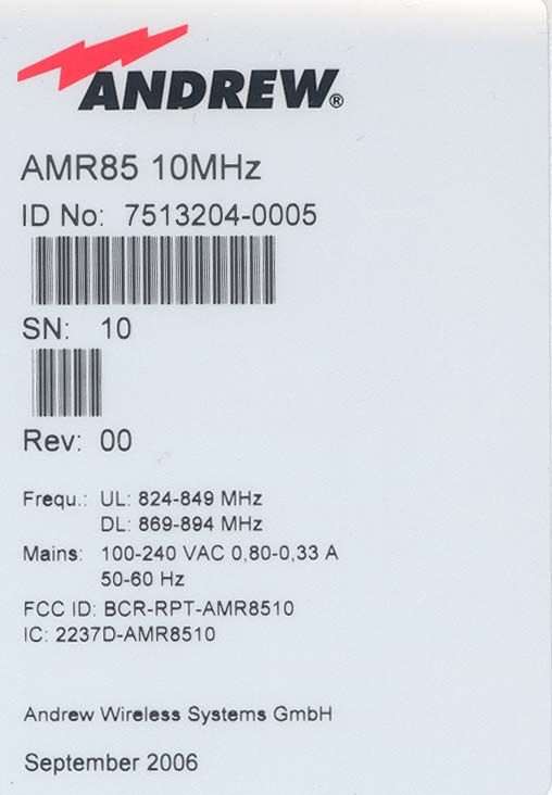
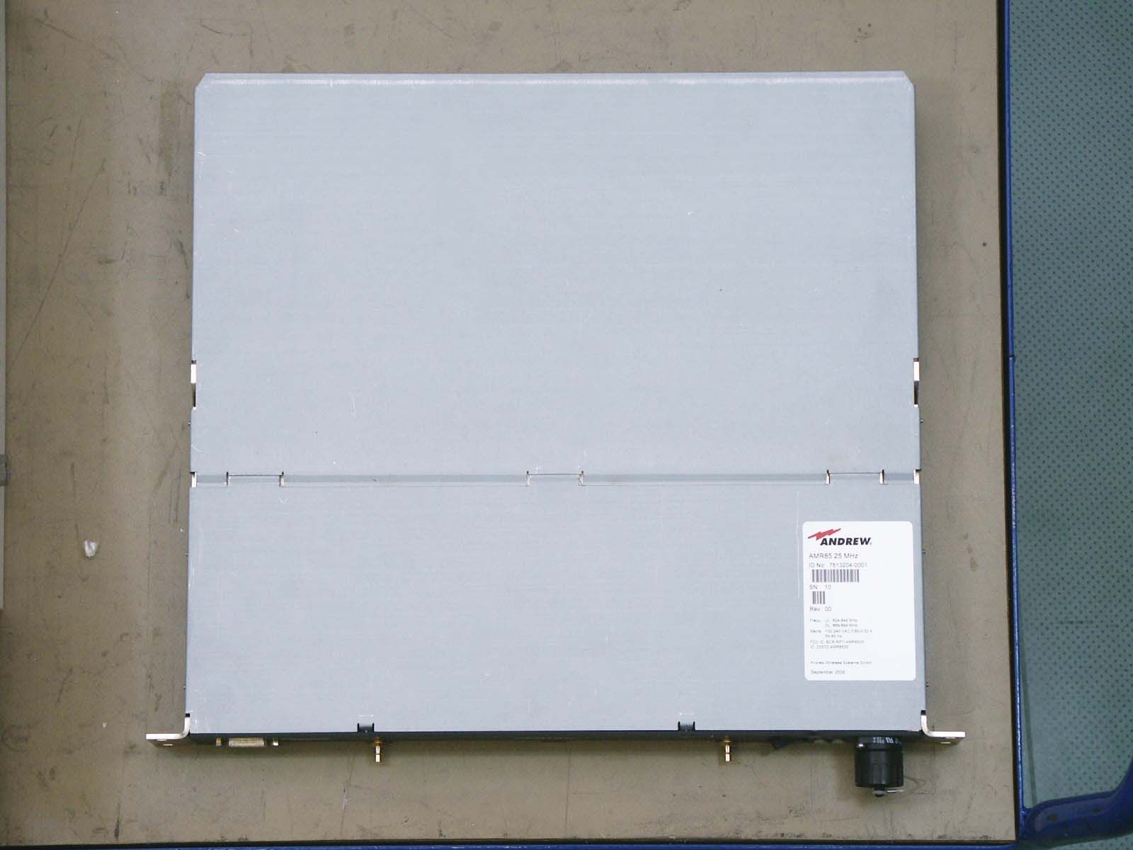
Document Text
Text extracted from the exhibit documents filed with the FCC. Open a document above to read the original.
Cover Letter(s)
Andrew Corporation 108 Rand Park Drive Garner, NC U.S.A. 27529 Tel: (919) 771-2570 Fax: (919) 771-2360 www.andrew.com 26 September 2006 Equipment Autorisation Division Federal Communications Commission 7435 Oakland Mills Road Columbia, MD 21046 FCC ID: BCR-RPT-AMR8510 Product Name: AMR80/90/19 Request for Confidentiality Pursuant to Sections 0.457 and 0.459 of the commission’s rules, we hereby request that the following documents be held confidential: • Schematics Labeled Schematics-AMR8510.pdf • Block diagram Labeled AMR Block Diagram.jpeg • Manual Labeled AMR Manual.pdf • Datasheet Labeled AMR Datasheet.pdf • Bill of Materials Labeled Schematics and BOMs rev.1.xls These materials contain trade secrets and proprietary information and are not customarily released to the public. The public disclosure of this information might be harmful to the company and provide unjustified benefits to our competitors. The manual is only provided for use by trained technicians and is not available to the general user from Andrew’s website. Dated this 26 Day of September 20 06 By: Michael Williamson Signature Printed Title: Product Manager On behalf of : Andrew Corporation Telephone: (919) 771-2570 x223
Parts List/Tune Up Info
AMR Tune-Up Procedure The first step in setting up the AMR is to set the frequency of the single stage SAW filter. The user may select the filter setting through the GUI. The next step is to set the appropriate attenuation of the AMR to provide the desired output power. There are two methods of setting the attenuation: manually or automatically. In manual mode, the user would measure the input signals and set the attenuation of the AMR to provide the desired output power. ALC is always functioning and the maximum output power of the AMR will never be exceeded. In automatic mode, the AMR will adjust gain to maximize output power, but no exceed the maximum ALC limit.
Test Report
Nemko Test Report: 6L0642RUS6 Applicant: Andrew Corporation 108 Rand Park Drive Garner, NC 27529 USA Equipment Under Test: AMR8510 (E.U.T.) In Accordance With: CFR 47, Part 22, Subpart H Cellular Band Repeaters Tested By: Nemko USA Inc. 802 N. Kealy Lewisville, TX 75057-3136 TESTED BY: DATE: 25 September 2006 David Light Wireless Engineer APPROVED BY: DATE: 29 September 2006 Kevin Rose Wireless Engineer Number of Pages: 70 Nemko USA, Inc. CFR 47, PART 22, SUBPART H CELLULAR BAND REPEATERS EQUIPMENT: AMR8510 PROJECT NO.: 6L0432RUS6 Page 2 of 70 Table of Contents SECTION 1. SUMMARY OF TEST RESULTS 3 SECTION 2. GENERAL EQUIPMENT SPECIFICATION 5 SECTION 3. RF POWER OUTPUT 7 SECTION 4. OCCUPIED BANDWIDTH 8 SECTION 5. SPURIOUS EMISSIONS AT ANTENNA TERMINALS 29 SECTION 6. FIELD STRENGTH OF SPURIOUS 56 SECTION 7. TEST EQUIPMENT LIST 58 ANNEX A - TEST DETAILS 59 ANNEX B - TEST DIAGRAMS 65 Nemko USA, Inc. CFR 47, PART 22, SUBPART H CELLULAR BAND REPEATERS EQUIPMENT: AMR8510 PROJECT NO.: 6L0432RUS6 Page 3 of 70 Section 1. Summary of Test Results Manufacturer: Andrew Corporation Model No.: AMR8510 Serial No.: None General: All measurements are traceable to national standards. These tests were conducted on a sample of the equipment for the purpose of demonstrating compliance with CFR 47, Part 22, Subpart H. New Submission Production Unit Class II Permissive Change Pre-Production Unit THIS TEST REPORT RELATES ONLY TO THE ITEM(S) TESTED. THE FOLLOWING DEVIATIONS FROM, ADDITIONS TO, OR EXCLUSIONS FROM THE TEST SPECIFICATIONS HAVE BEEN MADE. See “ Summary of Test Data”. Nemko USA Inc. authorizes the above named company to reproduce this report provided it is reproduced in its entirety and for use by the company’s employees only. Any use which a third party makes of this report, or any reliance on or decisions to be made based on it, are the responsibility of such third parties. Nemko USA Inc. accepts no responsibility for damages, if any, suffered by any third party as a result of decisions made or actions based on this report. This report applies only to the items tested. Nemko USA, Inc. CFR 47, PART 22, SUBPART H CELLULAR BAND REPEATERS EQUIPMENT: AMR8510 PROJECT NO.: 6L0432RUS6 Page 4 of 70 Summary Of Test Data NAME OF TEST PARA. NO. SPEC. RESULT RF Power Output 22.913(a) 500W ERP Complies Occupied Bandwidth Not defined Input/Output Complies Spurious Emissions at Antenna Terminals 22.917 -13 dBm Complies Field Strength of Spurious Emissions 22.917 -13 dBm E.I.R.P. Complies Frequency Stability 22.355 1.5 ppm NA Footnotes: (1) Modulation characteristics were not tested since the E.U.T. processes but does not produce a modulated waveform. . Nemko USA, Inc. CFR 47, PART 22, SUBPART H CELLULAR BAND REPEATERS EQUIPMENT: AMR8510 PROJECT NO.: 6L0432RUS6 Page 5 of 70 Section 2. General Equipment Specification Supply Voltage Input: 120 Vac Frequency Range: Downlink: 869-894 MHz Frequency Range: Uplink: 824-849 MHz CDMA GSM TDMA EDGE W-CDMA (F9W) (GXW) (DXW) (G7W) (F9W) Type of Modulation and Designator: Output Impedance: 50 ohms Downlink: 0.50 W RF Output (Rated): 27 dBm Uplink: 0.32 W 25 dBm Frequency Translation: F1-F1 F1-F2 N/A Software Duplexer Change Fullband Coverage Band Selection: Nemko USA, Inc. CFR 47, PART 22, SUBPART H CELLULAR BAND REPEATERS EQUIPMENT: AMR8510 PROJECT NO.: 6L0432RUS6 Page 6 of 70 Description of EUT Bi-directional amplifier used to enhance signals between a mobile and a base station in a wireless network. Typical applications are coverage improvement in small and medium sized environments such as offices, store fronts, underground floors, and small manufacturing facilities. The AMR family will automatically set its gain to maximize performance. However, an alphanumeric interface allows the user to manually set the gain if desired. ALC, Automatic Level Control, is incorporated to prevent overdriving the amplifier. System Diagram Nemko USA, Inc. CFR 47, PART 22, SUBPART H CELLULAR BAND REPEATERS EQUIPMENT: AMR8510 PROJECT NO.: 6L0432RUS6 Page 7 of 70 Section 3. RF Power Output NAME OF TEST: RF Power Output PARA. NO.: 22.913 TESTED BY: David Light DATE: 08 September 2006 Test Results: Complies. Test Data: Direction Modulation Output per Channel (dBm) Composite Power (dBm) Composite Power (W) Uplink CDMA 24.03 27.03 0.50 Downlink CDMA 22.01 25.01 0.32 Uplink TDMA 24.06 27.06 0.50 Downlink TDMA 22.02 25.02 0.32 Uplink EDGE 24.02 27.02 0.50 Downlink EDGE 22.00 25.00 0.32 Uplink GSM 24.04 27.04 0.50 Downlink GSM 22.01 25.01 0.32 Uplink W-CDMA 22.03 25.03 0.50 Downlink W-CDMA 20.00 23.00 0.32 Equipment Used: 1469-1472-1082-1659 Measurement Uncertainty: +/- 1.7 dB Temperature: 25 °C Relative Humidity: 40 % Nemko USA, Inc. CFR 47, PART 22, SUBPART H CELLULAR BAND REPEATERS EQUIPMENT: AMR8510 PROJECT NO.: 6L0432RUS6 Page 8 of 70 Section 4. Occupied Bandwidth NAME OF TEST: Occupied Bandwidth PARA. NO.: 2.1049 TESTED BY: David Light DATE: 08 September 2006 Test Results: Complies. Test Data: See attached plot(s). Equipment Used: 1469-1472-1082-1659-1036 Measurement Uncertainty: 1X10 -7 ppm Temperature: 25 °C Relative Humidity: 40 % Nemko USA, Inc. CFR 47, PART 22, SUBPART H CELLULAR BAND REPEATERS EQUIPMENT: AMR8510 PROJECT NO.: 6L0432RUS6 Page 9 of 70 Test Data – Occupied Bandwidth CDMA - Output Downlink A * RBW 30 kHz VBW 100 kHz SWT 5 ms Offset 30.8 dB LVL Ref 30 dBmAtt 30 dB Center 880 MHzSpan 3 MHz300 kHz/ *1 PK VIEW -70 -60 -50 -40 -30 -20 -10 0 10 20 30 Date: 11.SEP.2006 13:58:14 Nemko USA, Inc. CFR 47, PART 22, SUBPART H CELLULAR BAND REPEATERS EQUIPMENT: AMR8510 PROJECT NO.: 6L0432RUS6 Page 10 of 70 Test Data – Occupied Bandwidth CDMA - Input Downlink A * RBW 30 kHz VBW 100 kHz SWT 5 msAtt 0 dB * Ref -40 dBm Center 880 MHzSpan 3 MHz300 kHz/ *1 PK VIEW -140 -130 -120 -110 -100 -90 -80 -70 -60 -50 -40 Date: 11.SEP.2006 13:56:54 Nemko USA, Inc. CFR 47, PART 22, SUBPART H CELLULAR BAND REPEATERS EQUIPMENT: AMR8510 PROJECT NO.: 6L0432RUS6 Page 11 of 70 Test Data – Occupied Bandwidth CDMA - Ou…
Text truncated - open the document above for the full version.
Test Report
Voltage and Current into Final Devices AMR85 824-849 MHz PA 2 final MMIC devices in parallel, V = +5 VDC, I = 800 mA for each device 869-894 MHz PA 2 final MMIC devices in parallel, V = +5 VDC, I = 800 mA for each device
Contact Information
Applicant
Michael Shumate(Director, North American Operations)
Test Firm
Nemko USA, Inc.Tom Tidwell
Technical Specifications
| # | Rule Parts | Frequency Range | Power Output | Emission | Tolerance |
|---|---|---|---|---|---|
| 8 | 22 | 824 MHz - 849 MHz | 320.00 mW | G7W | Amp |
Other Applications from Andrew Wireless Innovations Group

BCR-IONEUAP
Mar 10, 2015ION-E
Equipment Class
B2I - Part 20 Industrial Booster (CMRS)
BCR-M17P26
Feb 08, 2012ION-M17P/26 EU
Equipment Class
TNB - Licensed Non-Broadcast Station Transmitter
BCR-TFAHUS717
Aug 14, 2011ION-B TFAH-US7/17
Equipment Class
TNB - Licensed Non-Broadcast Station Transmitter
BCR-TFAHUS4B
Jul 20, 2011ION-B TFAH-US4B
Equipment Class
PCB - PCS Licensed Transmitter
BCR-TFBM17
Jan 23, 2011ION-B TFBM17 FIBER OPTIC DISTRIBUTION REMOTE UNIT
Equipment Class
TNB - Licensed Non-Broadcast Station Transmitter