BCR-RPT-MMR8-19IBroad Band Repeater
Andrew Wireless Innovations Group
Click to zoom
Application Details
- Equipment Class
- PCB - PCS Licensed Transmitter
- Date of Grant
- May 12, 2004
- Application Purpose
- Original Equipment
- Date of Application
- May 12, 2004
- Equipment Note
- Broad Band Repeater
- Frequency Range
- 851.00000000 - 866.00000000
- Country
- United States
Documents & Files
Document Text
Text extracted from the exhibit documents filed with the FCC. Open a document above to read the original.
Users Manual
ID No: 159967Page 1 User’s Manual for Optical Remote Unit MMR8/19 (ID No 159207) User’s Manual for Remote Unit MMR8/19 Page 2M0106A7E.doc Copyright 2003 Mikom GmbH All rights reserved. All information contained in this manual has been revised thoroughly. Yet Mikom accepts no liability for any omissions or faults. Mikom reserves the right to change all hard- and software characteristics without notice. Names of products mentioned herein are used for identification purposes only and may be trademarks and/or registered trademarks of their respective companies. No parts of this publication may be reproduced, stored in a retrieval system, transmitted in any form or by any means, electronical, mechanical photocopying, recording or otherwise, without prior written permission of the publisher. Mikom GmbH An Andrew Company, 21-August-2003 ID No: 159967Page 3 TABLE OF CONTENTS 1.GENERAL7 1.1.USED ABBREVIATIONS7 1.2.HEALTH AND SAFETY WARNINGS8 1.3.PREAMBLE9 1.4.INTERNATIONAL CONTACT ADDRESSES10 2.INTRODUCTION11 2.1.PURPOSE11 2.2.THE MMR8/1911 3.FUNCTIONAL DESCRIPTION13 3.1.GENERAL13 3.2.COMPONENTS OF THE MMR8/19 REMOTE UNIT14 3.2.1.Components Inside the Unit14 3.2.2.Fan Protection Kit16 3.2.3.Accessories16 4.INSTALLATION17 4.1.MECHANICAL INSTALLATION17 4.1.1.General17 4.1.2.Wall Mounting Procedure19 4.1.3.Outside Pole Mounting Procedure20 4.1.4.Mounting of Fan Protection21 4.1.5.Suggestion for an Inside Pole Mounting Procedure22 4.2.ELECTRICAL INSTALLATION24 4.2.1.General24 4.2.2.Connections25 4.2.3.Grounding26 4.2.4.Power Connection27 4.2.5.Connection of the Antenna Cables27 4.2.6.Optical Fibre Cable Connection28 5.COMMISSIONING31 5.1.GENERAL31 5.2.AUTO-LEVELLING31 5.3.REMOTE OPERATION31 User’s Manual for Remote Unit MMR8/19 Page 4M0106A7E.doc 6.ALARMS33 6.1.BITE AND ALARMS33 6.2.HANDLING OF ALARMS33 6.3.STATUS REPORT33 6.4.LED ALARMS33 6.5.ALARM LIST34 7.MAINTENANCE35 7.1.GENERAL35 7.2.REPLACING THE FAN UNIT36 7.3.CLEANING THE HEAT SINK38 8.APPENDIX39 8.1.ILLUSTRATIONS39 8.2.SPECIFICATIONS40 8.2.1.Mechanical Specifications40 8.2.2.Optical and Interface Specifications40 8.2.3.Electrical Specifications40 8.2.4.Environmental and Safety Specifications42 8.3.SPARE PARTS42 9.INDEX43 ID No: 159967Page 5 FIGURES AND TABLES figure 3-1 Configuration of a MMR8/19 remote unit..................................................13 figure 3-2 Remote unit, front view.............................................................................14 figure 3-3 Remote unit, backside..............................................................................14 figure 3-4 Remote unit, left side................................................................................15 figure 3-5 Remote unit, right side..............................................................................15 figure 4-1 Tube installation........................................................................................18 figure 4-2 Wall mounting...........................................................................................19 figure 4-3 Pole mounting kit......................................................................................20 figure 4-4 Pole mounting...........................................................................................21 figure 4-5 Mounting procedure for fan protection......................................................22 figure 4-6 Mounting aid brackets...............................................................................23 figure 4-7 Connector flange......................................................................................25 figure 4-8 Grounding bolt with loosened hex nut.......................................................26 figure 4-9 Grounding bolt, schematic view................................................................26 figure 4-10 Tight kit...................................................................................................29 figure 7-1 Fan unit assembly.....................................................................................37 figure 8-1 Installation drawing...................................................................................39 table 1-1 List of international contact addresses.......................................................10 table 4-1 Specified torques.......................................................................................17 table 6-1 LED alarms................................................................................................33 User’s Manual for Remote Unit MMR8/19 Page 6M0106A7E.doc For your notes 1 General ID No: 159967Page 7 1. GENERAL 1.1. USED ABBREVIATIONS ALCAutomatic Level Control AMPSAmerican Mobile Phone System or Advanced Mobile Phone System APACAutomatic Power Adjustment Circuit BCCHBroadcast Control Channel BITEBuilt In Test Equipment BTSBase Transceiver Station CDMACode Division Multiple Access CEPTConférénce Européenne des Postes et Télécommunications CFCenter Frequency CFOCenter Frequency Offset DLDownlink EDGEEnhanced Data Rates for GSM Evolution ESDElectrostatic Discharge ETACSEnhanced TACS ETSEuropean Telecommunication Standard ETSIEuropean Telecommunication Standards Institute FSKFrequency Shift Keying GSMGlobal System for Mobile Communication I 2 C-BusInter Integrated Circuit Bus (Philips) ID NoIdentification Number IFIntermediate Frequency LMTLocal Maintenance Terminal MORMikom Optical Remote unit MSMobile Station OMCOperation and Maintenance Center PCMCIAPersonal Computer Modem Communication International Association PCSPersonal Communication System PSTNPublic Switched Telephone Network RevRevision RFRadio Frequency RLPRadio Link Protocol RSSIReceive Signal Strength Indication RTCReal Time Clock RXReceiver SCLSerial Clock SDASerial Data TACSTotal Access Communication System TCHTraffic Channel TDMATime Division Multiple Access TXTransmitter ULUplink UMTSUniversal Mobile Telecommunication System UPSUninterruptable Power Supply VSWRVoltage Standing Wave…
Text truncated - open the document above for the full version.
Block Diagram
MMR Host Block Diagram E O E O RX 800/1900 MHz WDM 1900 MHz 800 MHz MMR Remote Unit TX 800/1900 MHz UL UL DL DL 800 MHz BTS 1900 MHz BTS Optical Fiber Cellular telephone systems transmit signals in two directions between base transceiver station (BTS) and mobile stations (MS) within the signal coverage area. If weak signal transmissions occur within the coverage area because of indoor applications, topological conditions or distance from the transmitter, extension of the transmission range can be achieved by means of an optical distribution system. Such a system contains an optical master unit and several remote units. The remote units are connected to the master unit with optical links, which must have an optical loss of less than 10 dB. The optical transmission uses WDM-systems with a wavelength of 1550 nm in the uplink and 1310 nm in the downlink. An auto-leveling function for compensating different fibre losses is implemented to maintain a constant gain in the downlink and uplink paths. The MMR master unit, which is the link between the remote units and BTS, is comprised of two signal chains. In the uplink direction, the optical signals from the remote units (transmitted via optical fibres) are converted into RF signals by the transceiver. Then, they are forwarded via a frequency separation unit denominated as duplexer to the BTS. In the downlink direction, the signals from the BTS are forwarded to the duplexer where the RF signals are converted into optical signals by the transceiver and finally are transmitted via optical fibres to the remote units. The downlink gain from the duplexer input to the MMR remote output is approximately 30 dB. Depending upon the number of RF carriers, the RF input level to the duplexer is in the range of 0 dBm to +10 dBm. External attenuators would be used to reduce the output power from the BTS to these levels. In the uplink path the system gain from the MMR remote unit to the BTS input should be in the range of -5 dB to 0 dB. Setting the uplink system gain to these values will insure that the signal levels present at the BTS input receiver would be of the same level as seen by the input of MMR unit and not cause the BTS receiver from being overdriven. Typical signal level input range to the BTS will be -40 dBm to -100 dBm. MMR Master
External Photos
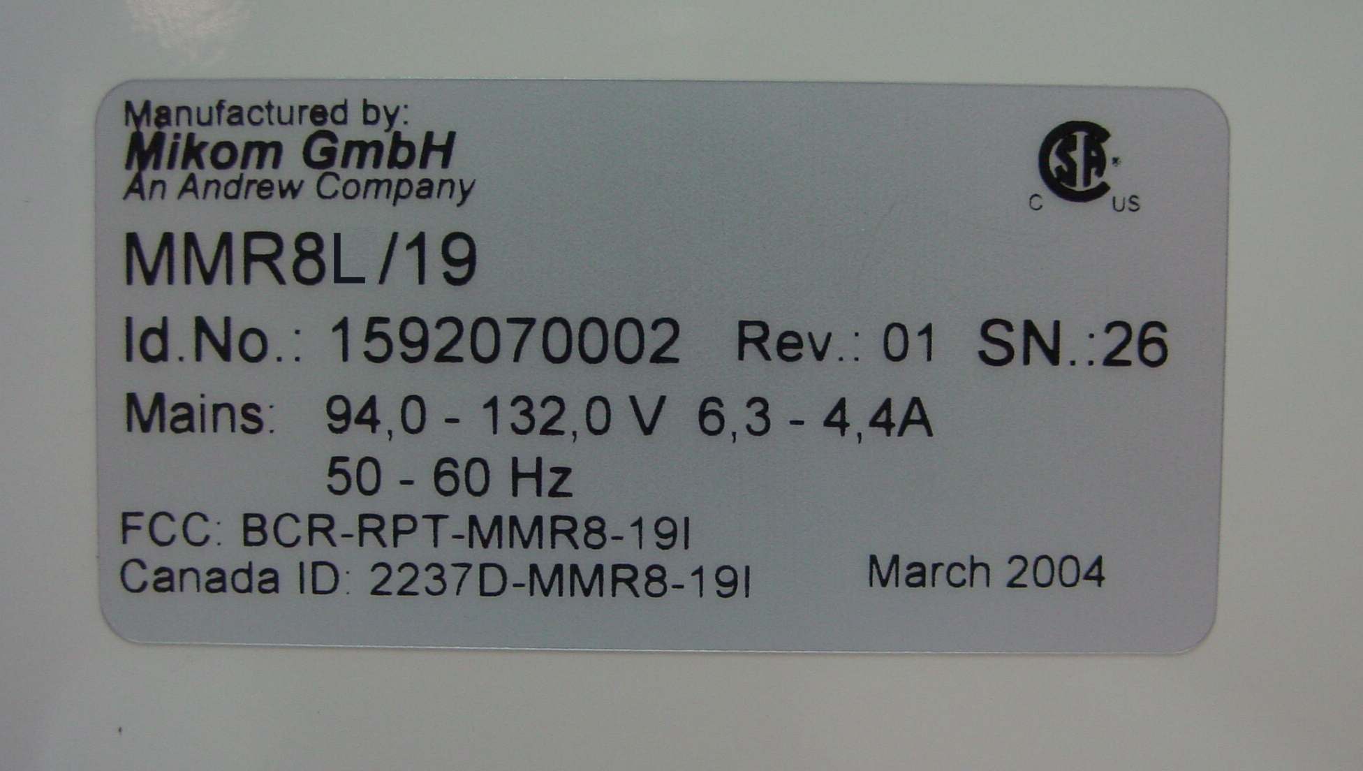
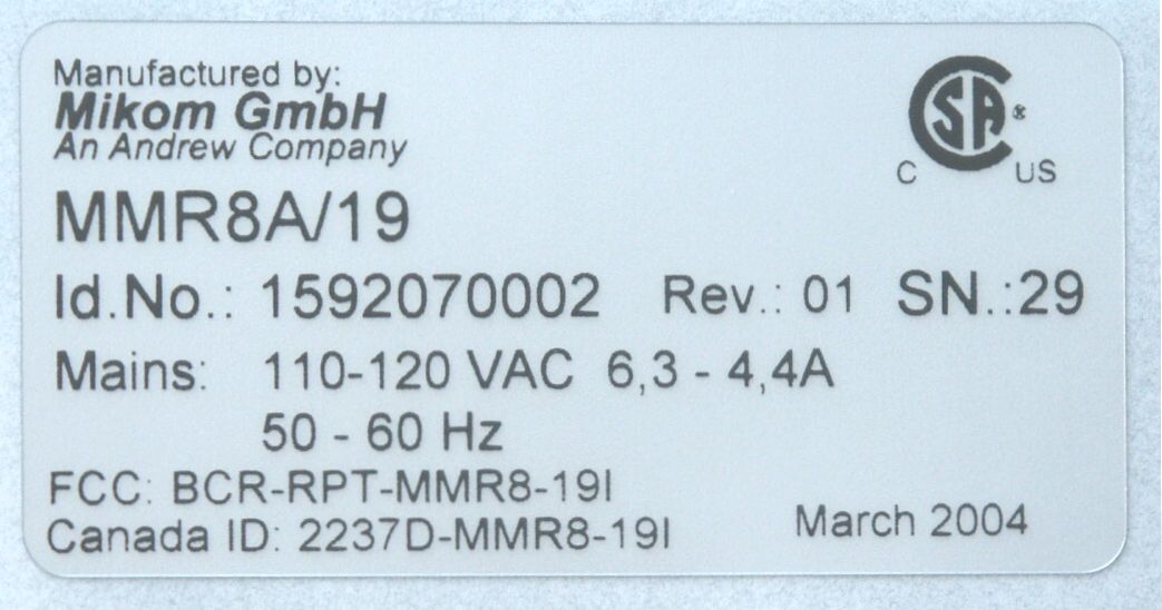
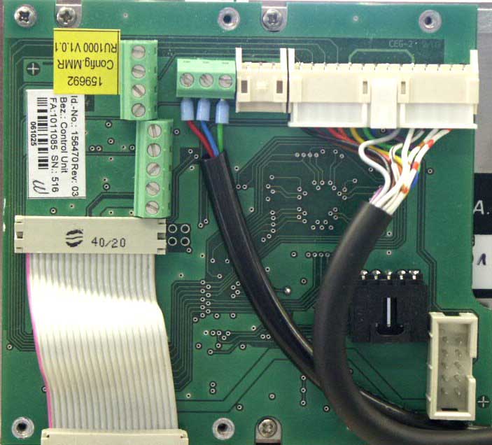
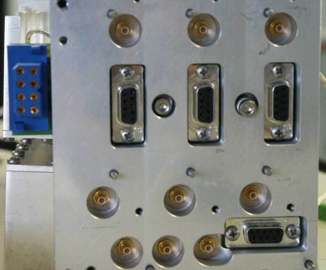
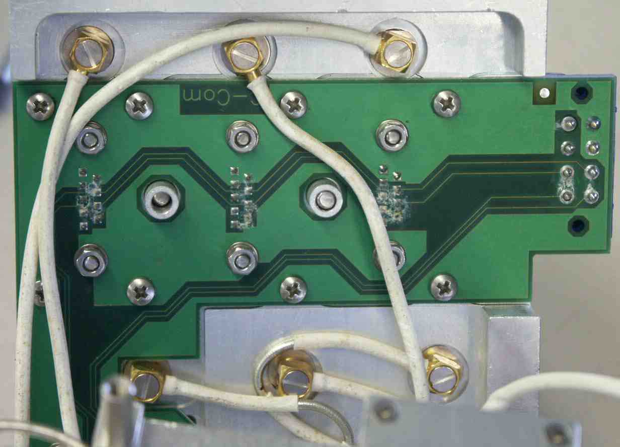
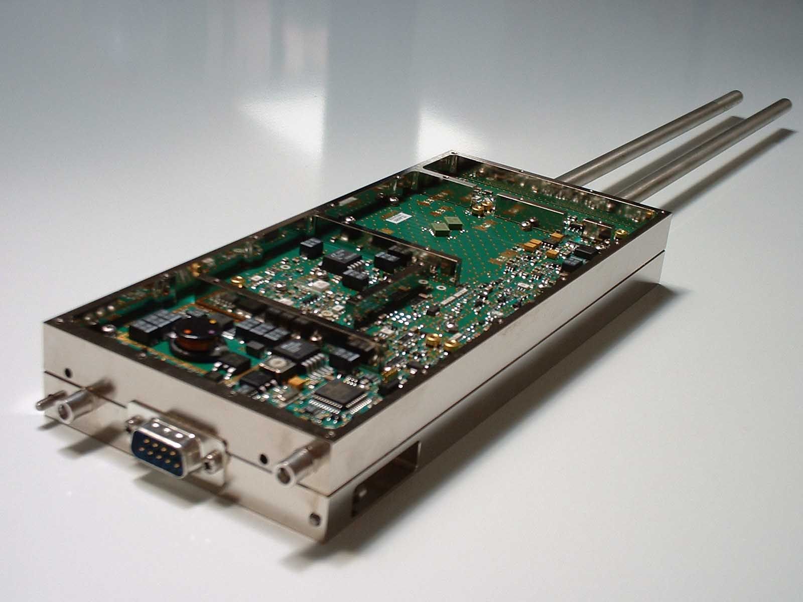
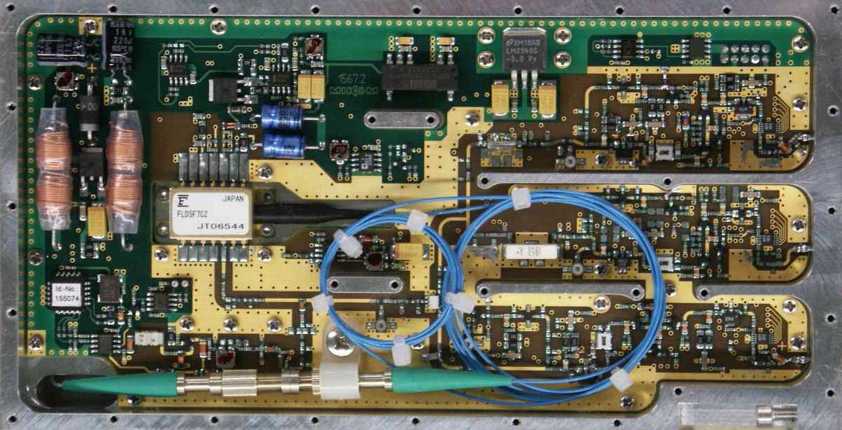
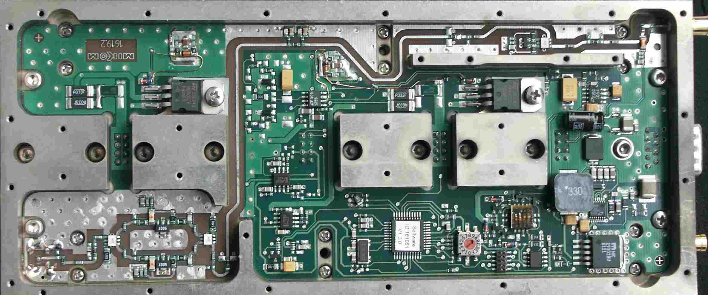
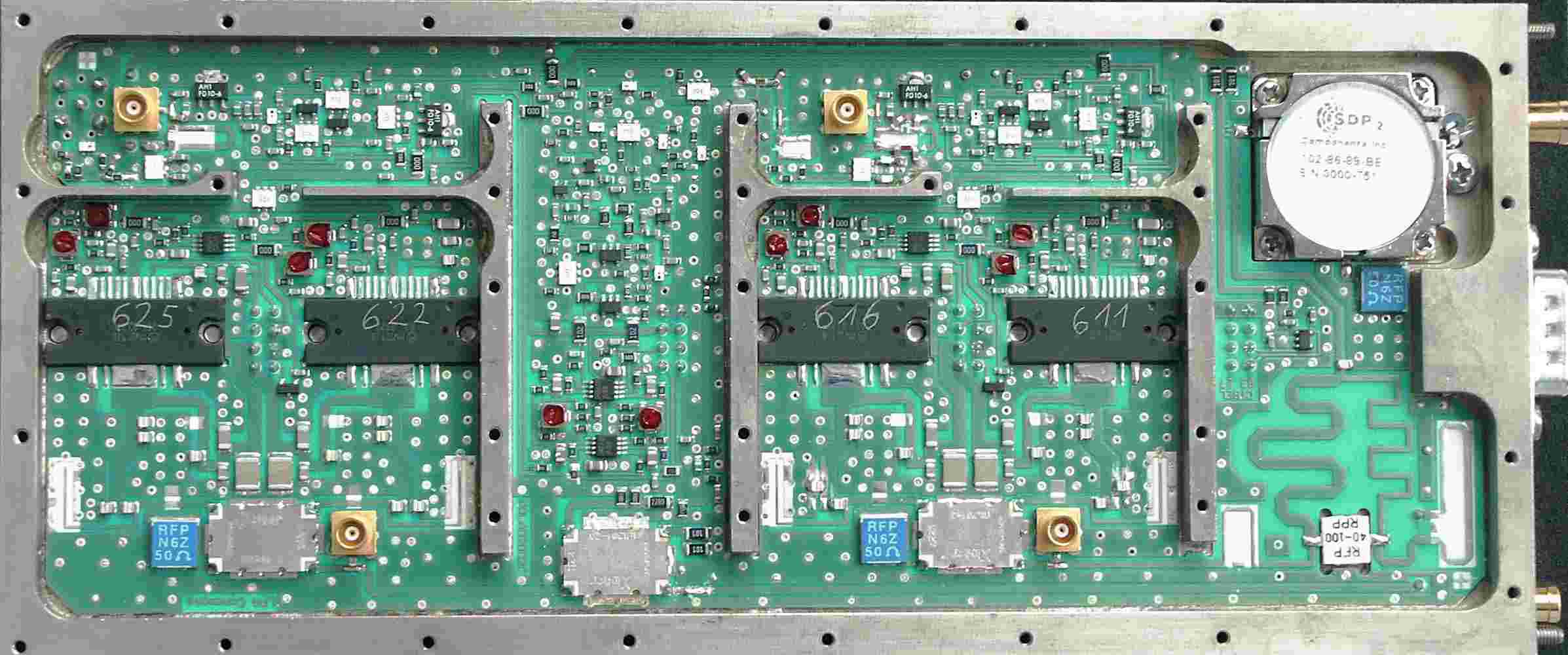
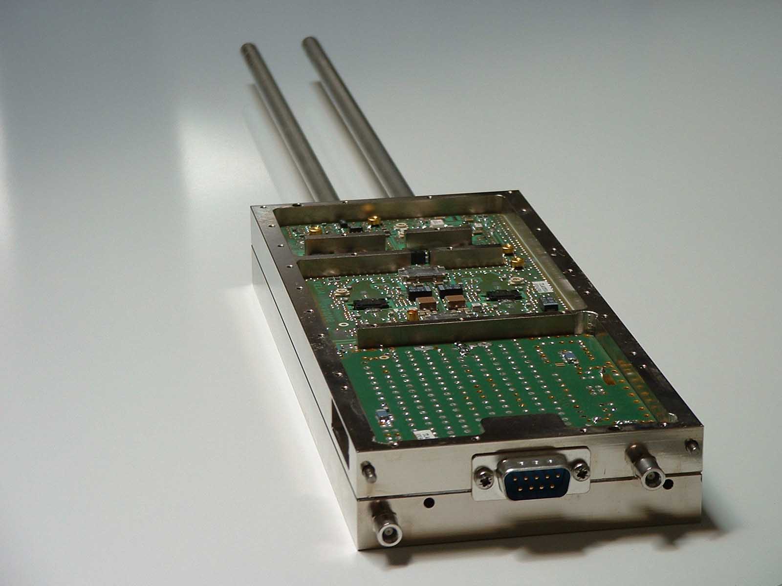
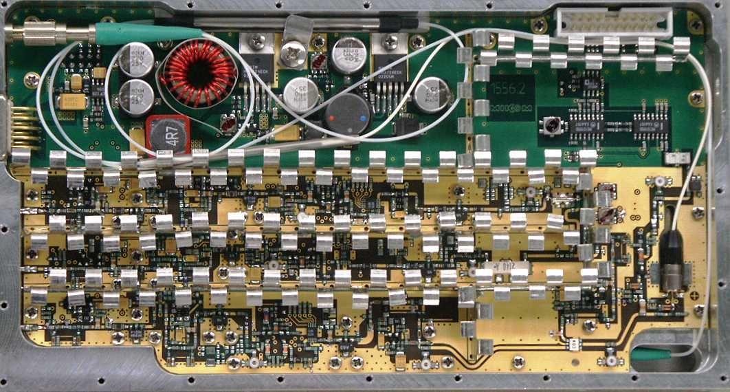
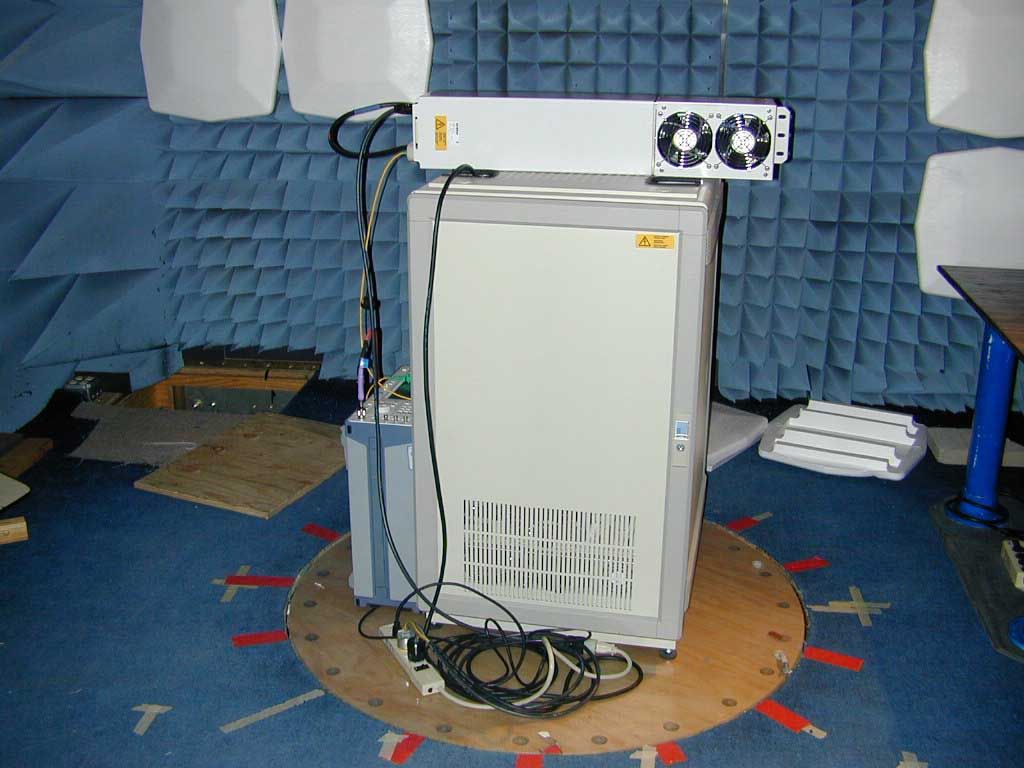
MMR8-19I Pictures Front Back Left Right Top Bottom Label – Right Side
Operational Description
Description of the Operational Characteristics of the MMR The RF signal directly modulates the intensity of a high linearity electro-optical device (laser). Therefore, the RF signal amplitude modulates the intensity of the laser and is superimposed on the light source. An optical receiver consisting of a PIN diode is used to convert the light signal back to RF, while maintaining the integrity of the original signal. The RF signal is not demodulated or altered from input to output of the equipment. Auto-leveling is implemented to maintain a constant system gain independent of changes to loss in the fiber transport path. RF attenuators are placed before the optical transmitter and after the optical receiver. The optical power from the optical transmitter is a fixed value and the optical receive strength at the optical receiver is measured to provide the optical loss in the optical fiber. A table is used to define the attenuation values that will be used depending upon the loss in the optical fiber.
Operational Description
Voltage and Current into Final Devices of the MMR 851-869 MHz PA 4 final devices in parallel, V = +28 VDC, I = 1.55 amps for each device 869-894 MHz PA 4 final devices in parallel, V = +28 VDC, I = 1.55 amps for each device 1930-1990 MHz PA 2 final devices in parallel, V = +28 VDC, I = 2.55 amps for each device
Parts List/Tune Up Info
1. MMR Remote Unit Tune-Up Procedure Included in this document are commands used to get and set various MMR remote unit parameters. The only parameter that needs to be adjusted during field installation is the Attenuation parameter. All other parameters are factory set. Inject an RF carrier of know power into the master and measure output power of that carrier at the MMR remote RF connector. The difference between those signal levels is the system gain. Using the Set Attenuation command described in Section 1.1.19, set the attenuation to obtain the designed system gain. 1.1 Local Commands for MMR Remote Unit 1.1.1 Software version Syntax: g ver↵ Gets the software version of the remote unit software. Response example: -> RU0000 V2.1.0.0 1.1.2 Software ID Syntax ‘get’ command: g sid↵ Syntax ‘set’ command: s sid=1234567890↵ Get/set the software the ANDREW software identification number of the remote unit software. Response example: -> SW-ID: 1234567890 1.1.3 Hardware revision Syntax ‘get’ command: g rev↵ Syntax ‘set’ command: s rev=1.23↵ Get/set the hardware revision of the remote unit. Note: This command is obsolete Response example: -> Rev: 1.23 1.1.4 Hardware ID Syntax ‘get’ command: g hid↵ Syntax ‘set’ command: s hid=1234567890↵ Get/set the software the ANDREW hardware identification number of the remote unit. Response example: Î HW-ID: 1234567890 1.1.5 Serial number Syntax ‘get’ command: g ser↵ Syntax ‘set’ command: s ser=1234567890↵ Get/set a serial number of the remote unit. Response example: -> SN: 1234567890 1.1.6 Module Type Syntax ‘get’ command: g mtp↵ Syntax ‘set’ command: s mtp=1234↵ Get/set a unique module type of the remote unit. Response example: Î M-TYPE: 1234 1.1.7 Fixed address Syntax ‘get’ command: g adr↵ Syntax ‘set’ command: s adr=value↵ value ={1..4} sub address, if this RU is used as cascaded RU Get/set the sub address. This address is linked with the laser frequency used in this RU. Response: -> ok 1.1.8 Configuration switches Syntax ‘get’ command: g cfg↵ Syntax ‘set’ command: s cfg=012F↵ Get/set a 2 byte configuration word. The bits of this two bytes allow hard- and software configuration. For exact meaning of the single bits see Error! Reference source not found. . Response example of a get command: -> CFG: 012F 1.1.9 Attenuation Syntax ‘get’ command: g att↵ Syntax ‘set’ command: s att index=value↵ index = 1 ...6 value = 000 ... 030 [dB] e.g. index refers to the following amplifiers 1 = UMTS UL, 2 = UMTS DL, 3 = DCS UL, 4 = DCS DL, 5 = GSM UL, 6 = GSM DL Example for a set command: s att 2=10↵ => set attenuation UMTS DL = 10dB Response example of a get command: -> 012 014 016 009 021 023 dB 1.1.10 Gain offset Syntax ‘get’ command: g ofs↵ Syntax ‘set’ command: s ofs index=value↵ index = 1 ...6 value = -9..9 [dB] e.g. index refers to the following amplifiers 1 = UMTS UL, 2 = UMTS DL, 3 = DCS UL, 4 = DCS DL, 5 = GSM UL, 6 = GSM DL Examples for set commands: s ofs 3=6↵ => set ofs DCS UL = +6dB s ofs 6=-9↵ => set ofs GSM DL = -9dB Note: sign is necessary for minus Response example of a get command: -> -01 +02 +01 -02 +02 +00 dB 1.1.11 ALC value Syntax ‘get’ command: g alc↵ Syntax ‘set’ command: s alc index=value↵ index = 1 ... 6 value = 0 ... 255 e.g. index refers to the following amplifiers 1 = UMTS UL, 2 = UMTS DL, 3 = DCS UL, 4 = DCS DL, 5 = GSM UL, 6 = GSM DL Examples for set commands: s alc 1=145↵ => set alc UMTS UL = 145 s alc 5=88↵ => set alc GSM UL = 88 Response example of a get command: -> 255 253 199 177 099 123 1.1.12 FSK Dynamic Syntax ‘get’ command: g fsk↵ Syntax ‘set’ command: s fsk index=value↵ index = 2 value = 0...255 (Default value is 127) Set example: s fsk 2=150 => set FSK dynamic in Remote Unit = 150 Response of a get command: -> xxx 150 => FSK dynamic = 150, ignore xxx Note: index=2 when connected to the master unit or index=1 when connected to the remote unit won’t have any effect. 1.1.13 External Outputs Set external outputs and read the status of external outputs. Syntax ‘get’ command: g ext↵ Syntax ‘set’ command: s ext index=value↵ index = 1..4 (external output 1..4) value = 0/1 (0 = reset, 1= set) Set example: s ext 3=0 => reset external output 3 Get response: -> 1 0 1 0 (output 1=reset, output 2=set, output 3=reset, output 2=set) 1.1.14 Status Get all status and alarm flags. Syntax ‘get’ command: g sta↵ Get response: -> xx xx xx xx xx see Error! Bookmark not defined. for detailed information 1.1.15 Current window (optical module) Since optic module revision 2, current alarms are detected by monitoring 4 different currents with a AD- converter. This is for UL and DL. By starting the software the very first time, default values for low and high limits of a current range are stored non volatile. Each value can be changed manually. Get current window low/high limit: Syntax ‘get’ command: g cwl↵ or g cwh↵ Get response: -> current low: 028 018 003 002 018 000 009 007 high: 048 028 010 008 028 002 015 013 avg: 039 024 009 007 020 000 015 007 Both get commands deliver the same result. The first row contains the lower limits, the second row the higher limits and the third row the actual measured value. Set current window low/high limit: Syntax ‘set’ command low limit: s cwl index=value↵ Syntax ‘set’ command high limit: s cwh index=value↵ index {1...8} value {0...255} index: 1=ADC channel 1 on RX board, ..., 4=ADC channel 4 on RX board, 5=ADC channel 1 on TX board, ..., 8=ADC channel 1 on TX board value: t. b. d. 1.1.16 Place amplifier command Syntax ‘get’ command: g amp↵ Syntax ‘set’ command: s amp index=value↵ index {1..3} value {0,1} Index: 1 = Amplifier 1, 2 = Amplifier 2, 3 = Amplifier 3 value: 0 = declare amplifier as ‘not placed’, 1 = declare amplifier as ‘placed’ This command serves to configure an amplifier as placed or not placed. It will be necessary when there is a system with less than three amplifiers, for example a 2 Band system with GSM and DCS, being the UMTS amplifier not placed. Example: s amp 1=1 => configure amplifier number 1 as n…
Text truncated - open the document above for the full version.
Test Report
Nemko Test Report No.: 3L0498RUS1 Applicant: Andrew Corporation Equipment Under Test: Optical Repeater In Accordance With: FCC Part 24, Subpart E Broadband PCS Repeaters Tested By: Nemko USA Inc. 802 N. Kealy Lewisville, Texas 75057-3136 Authorized By: Tom Tidwell, RF Group Manager Date: 4/22/04 Total Number of Pages: 48 Nemko Dallas FCC PART 24, SUBPART E BROADBAND PCS REPEATERS EQUIPMENT: Optical Repeater FCC ID: PROJECT NO.: 3L0498R Page 2 of 49 Table of Contents Section 1. Summary of Test Results...............................................................3 Section 2. General Equipment Specification....................................................5 Section 3. RF Power Output..........................................................................9 Section 4. Occupied Bandwidth...................................................................10 Section 5. Spurious Emissions at Antenna Terminals.....................................31 Section 6. Field Strength of Spurious...........................................................34 Section 7. Frequency Stability......................................................................37 Section 8. Test Equipment List.....................................................................38 ANNEX A - TEST DETAILS..........................................................................39 ANNEX B - TEST DIAGRAMS......................................................................45 Nemko Dallas FCC PART 24, SUBPART E BROADBAND PCS REPEATERS EQUIPMENT: Optical Repeater FCC ID: PROJECT NO.: 3L0498R Page 3 of 49 Section 1. Summary of Test Results Manufacturer: Andrew Corporation Model No.: MMR Optical Master MMR 8A/19 MMR 8/19 Serial No.: 30 14 30 General: All measurements are traceable to national standards. These tests were conducted on a sample of the equipment for the purpose of demonstrating compliance with FCC Part 24, Subpart E. New Submission Production Unit Class II Permissive Change Pre-Production Unit THIS TEST REPORT RELATES ONLY TO THE ITEM(S) TESTED. THE FOLLOWING DEVIATIONS FROM, ADDITIONS TO, OR EXCLUSIONS FROM THE TEST SPECIFICATIONS HAVE BEEN MADE. See “ Summary of Test Data”. Nemko USA Inc. authorizes the above named company to reproduce this report provided it is reproduced in its entirety and for use by the company’s employees only. Any use which a third party makes of this report, or any reliance on or decisions to be made based on it, are the responsibility of such third parties. Nemko USA Inc. accepts no responsibility for damages, if any, suffered by any third party as a result of decisions made or actions based on this report. This report applies only to the items tested. Nemko Dallas FCC PART 24, SUBPART E BROADBAND PCS REPEATERS EQUIPMENT: Optical Repeater FCC ID: PROJECT NO.: 3L0498R Page 4 of 49 Summary Of Test Data NAME OF TEST PARA. NO. SPEC. MEAS. RESULT RF Power Output 24.232 100W 24.83W Complies Occupied Bandwidth (CDMA) 24.238 Input/Output NA Complies Occupied Bandwidth (GSM) 24.238 Input/Output NA Complies Occupied Bandwidth (NADC) 24.238 Input/Output NA Complies Spurious Emissions at Antenna Terminals 24.238(a) -13 dBm Plots Complies Field Strength of Spurious Emissions 24.238(a) -13 dBm E.I.R.P. E.I.R.P. Complies Frequency Stability 24.235 Footnotes: (1) Modulation characteristics were not tested since the E.U.T. processes but does not produce a modulated waveform. Measurement uncertainty for each test configuration is expressed to 95% probability. Nemko Dallas FCC PART 24, SUBPART E BROADBAND PCS REPEATERS EQUIPMENT: Optical Repeater FCC ID: PROJECT NO.: 3L0498R Page 5 of 49 Section 2. General Equipment Specification Supply Voltage Input: 115V AC Frequency Bands: Downlink: Block A : 1930 – 1945 MHz Block D : 1945 – 1950 MHz Block B : 1950 – 1965 MHz Block E : 1965 – 1970 MHz Block F : 1970 – 1975 MHz Block C : 1975 – 1990 MHz Frequency Bands: Uplink: Block A : 1850 – 1865 MHz Block B : 1865 – 1870 MHz Block C : 1870 – 1885 MHz Block D : 1885 – 1890 MHz Block E : 1890 – 1895 MHz Block F : 1895 – 1910 MHz CDMA GSM NADC (F9W) (GXW) (DXW) Type of Modulation and Designator: Output Impedance: 50 ohms Max Input: +20 dBm Per channel: NA W RF Output (Rated): Uplink Total: NA W CDMA 33 dBm (2 Carrier) RF Output (Rated): (Per Carrier) Downlink NADC 36 dBm (2 Carrier) GSM 39 dBm (2 Carrier) F1-F1 F1-F2 N/A Frequency Translation: Band Selection: Software Duplexer Fullband Nemko Dallas FCC PART 24, SUBPART E BROADBAND PCS REPEATERS EQUIPMENT: Optical Repeater FCC ID: PROJECT NO.: 3L0498R Page 6 of 49 Nemko Dallas FCC PART 24, SUBPART E BROADBAND PCS REPEATERS EQUIPMENT: Optical Repeater FCC ID: PROJECT NO.: 3L0498R Page 7 of 49 Modifications Made During Testing No modifications made during testing. Nemko Dallas FCC PART 24, SUBPART E BROADBAND PCS REPEATERS EQUIPMENT: Optical Repeater FCC ID: PROJECT NO.: 3L0498R Page 8 of 49 System Diagram Nemko Dallas FCC PART 24, SUBPART E BROADBAND PCS REPEATERS EQUIPMENT: Optical Repeater FCC ID: PROJECT NO.: 3L0498R Page 9 of 49 Section 3. RF Power Output NAME OF TEST: RF Power Output PARA. NO.: 2.1046 TESTED BY: Dustin Oaks DATE: 12/18/2003 Test Results: Complies. Measurement Data: Modulation Type Output Power (dBm) Uplink CDMA NA Downlink CDMA 39.05 Uplink GSM NA Downlink GSM 43.95 Uplink NADC NA Downlink NADC 41.05 Equipment Used: 1036, 1625, 1629, 1604, 1474, 1053 Measurement Uncertainty: +/- 1.6 dB Temperature: 21 ?C Relative Humidity: 51 % Nemko Dallas FCC PART 24, SUBPART E BROADBAND PCS REPEATERS EQUIPMENT: Optical Repeater FCC ID: PROJECT NO.: 3L0498R Page 10 of 49 Section 4. Occupied Bandwidth NAME OF TEST: Occupied Bandwidth (CDMA) PARA. NO.: 2.1049 TESTED BY: Dustin Oaks DATE: 12/17/2003 Test Results: Complies. Test Data: See attached plot(s). Equipment Used: 1036, 1625, 1629, 1604, 1474, 1053 Measurement Uncertainty: +/- 1.6 dB Temperature: 21 ?C Relative Humidity: 51 % Nemko Dallas FCC PART 24, SUBPART E BROADBAND PCS REPEATERS EQUIPMENT: Optical Repeater FCC ID…
Text truncated - open the document above for the full version.
Test Report
Master: ktlPT90PLMR Date: April 19, 1999 Nemko Test Report: 3L0498RUS3 Applicant: Andrew Corporation Equipment Under Test: Optical Repeater (E.U.T.) In Accordance With: FCC Part 90, Subpart I Private Land Mobile Repeater Tested By: Nemko USA Inc. 802 N. Kealy Lewisville, TX 75057-3136 Authorized By: Tom Tidwell, Frontline Manager Date: 4/22/04 Total Number of Pages: 33 Nemko USA FCC PART 90, SUBPART I PRIVATE LAND MOBILE REPEATER EQUIPMENT: Optical Repeater PROJECT NO.: 3L0498R Page 2 of 33 Table of Contents Section 1. Summary of Test Results.............................................................................................3 Section 2. General Equipment Specification...................................................................................5 Section 3. RF Power Output........................................................................................................8 Section 4. Occupied Bandwidth....................................................................................................9 Section 5. Spurious Emissions at Antenna Terminals.....................................................................16 Section 6. Field Strength of Spurious Emissions............................................................................19 Section 7. Frequency Stability......................................................................................................22 Section 8. Test Equipment List....................................................................................................23 ANNEX A - TEST METHODOLOGIES.........................................................................................24 ANNEX B - TEST DIAGRAMS.....................................................................................................30 Nemko USA FCC PART 90, SUBPART I PRIVATE LAND MOBILE REPEATER EQUIPMENT: Optical Repeater PROJECT NO.: 3L0498R Page 3 of 33 Section 1. Summary of Test Results Manufacturer: Andrew Corporation Model No.: MMR Optical Master Unit MMR 8/19 Serial No.: 30 12 General: All measurements are traceable to national standards. These tests were conducted on a sample of the equipment for the purpose of demonstrating compliance with FCC Part 90, Subpart I. New Submission Production Unit Class II Permissive Change Pre-Production Unit THIS TEST REPORT RELATES ONLY TO THE ITEM(S) TESTED. THE FOLLOWING DEVIATIONS FROM, ADDITIONS TO, OR EXCLUSIONS FROM THE TEST SPECIFICATIONS HAVE BEEN MADE. See “ Summary of Test Data”. Nemko USA Inc. authorizes the above named company to reproduce this report provided it is reproduced in its entirety and for use by the company’s employees only. Any use which a third party makes of this report, or any reliance on or decisions to be made based on it, are the responsibility of such third parties. Nemko USA Inc. accepts no responsibility for damages, if any, suffered by any third party as a result of decisions made or actions based on this report. This report applies only to the items tested. Nemko USA FCC PART 90, SUBPART I PRIVATE LAND MOBILE REPEATER EQUIPMENT: Optical Repeater PROJECT NO.: 3L0498R Page 4 of 33 Summary Of Test Data NAME OF TEST PARA. NO. SPEC. MEAS. RESULT RF Power Output 90.205 39.02 Complies Audio Frequency Response TIA EIA-603.3.2.6 N/A N/A N/A Audio Low-Pass Filter Response TIA EIA-603.3.2.6 N/A N/A N/A Modulation Limiting TIA EIA-603.3.2.6 N/A N/A N/A Occupied Bandwidth 90.210 Plots Plots Complies Spurious Emissions at Antenna Terminals 90.210 -13 dBm Plots Complies Field Strength of Spurious Emissions 90.210 -13 dBm E.R.P. E.R.P. Complies Frequency Stability 90.213 Complies Transient Frequency Behavior 90.214 N/A N/A N/A Footnotes For N/A’s: (1) Since the E.U.T. does not contain modulation circuitry modulation testing was not performed. (2) Since the E.U.T. is not a keyed carrier system, Transient Frequency Behavior was not performed. Indoor Temperature: ________21?C Humidity: ________51% Outdoor Temperature: ________19 ?C Humidity: ________65 % . Nemko USA FCC PART 90, SUBPART I PRIVATE LAND MOBILE REPEATER EQUIPMENT: Optical Repeater PROJECT NO.: 3L0498R Page 5 of 33 Section 2. General Equipment Specification Transmitter Supply Voltage Input: 115V AC Frequency Range: 451-466MHz Tunable Bands: 451-466MHz 20 dB Passband: Type(s) of Modulation: F3E (Voice) F1D F2D D7W (QAM) Other Maximum Input: +20dBm Output Impedance: NA RF Power Output (rated): Single: 39dBm Composite: 34dBm Frequency Translation: F1-F1 F1-F2 N/A Band Selection: Software Duplexer Change Fullband Coverage Nemko USA FCC PART 90, SUBPART I PRIVATE LAND MOBILE REPEATER EQUIPMENT: Optical Repeater PROJECT NO.: 3L0498R Page 6 of 33 Modifications Made During Testing No Modifications made during testing Nemko USA FCC PART 90, SUBPART I PRIVATE LAND MOBILE REPEATER EQUIPMENT: Optical Repeater PROJECT NO.: 3L0498R Page 7 of 33 System Diagram Nemko USA FCC PART 90, SUBPART I PRIVATE LAND MOBILE REPEATER EQUIPMENT: Optical Repeater PROJECT NO.: 3L0498R Page 8 of 33 Section 3. RF Power Output NAME OF TEST: RF Power Output PARA. NO.: 2.985 TESTED BY: Dustin Oaks DATE: 12/17/2003 Test Results: Complies Measurement Data: Frequency (MHz) Measured Power (dBm) Rated Power (dBm) Measured/Rated (dB) 851.0125 39.02 39 +0.02 865.9875 39.01 39 +0.01 Equipment Used: 1036, 1625, 1629, 1604, 1474, 1053 Measurement Uncertainty: +/- 1.6 dB Temperature: 21 ?C Relative Humidity: 51 % Nemko USA FCC PART 90, SUBPART I PRIVATE LAND MOBILE REPEATER EQUIPMENT: Optical Repeater PROJECT NO.: 3L0498R Page 9 of 33 Section 4. Occupied Bandwidth NAME OF TEST: Occupied Bandwidth PARA. NO.: 2.989 TESTED BY: Dustin Oaks DATE: 12/18/2003 Test Results: Complies Test Data: See attached graph(s). Equipment Used: 1036, 1625, 1629, 1604, 1474, 1053 Measurement Uncertainty: +/- 1.6 dB Temperature: 21 ?C Relative Humidity: 51 % Nemko USA FCC PART 90, SUBPART I PRIVATE LAND MOBILE REPEATER EQUIPMENT: Optical Repeater PROJECT NO.: 3L0498R Page 10 of 33 Band Width and Input/Out…
Text truncated - open the document above for the full version.
Contact Information
Applicant
Michael Shumate(Director, North American Operations)
Technical Contact
Non-Technical Contact
Nemko USADustin Oaks
[email protected]972-436-9600
Test Firm
Nemko USA, Inc.Tom Tidwell
Technical Specifications
| # | Rule Parts | Frequency Range | Power Output | Emission | Tolerance |
|---|---|---|---|---|---|
| 4 | 9 | 851 MHz - 866 MHz | 7.98 W | D7W | Amp |
Other Applications from Andrew Wireless Innovations Group

BCR-IONEUAP
Mar 10, 2015ION-E
Equipment Class
B2I - Part 20 Industrial Booster (CMRS)
BCR-M17P26
Feb 08, 2012ION-M17P/26 EU
Equipment Class
TNB - Licensed Non-Broadcast Station Transmitter
BCR-TFAHUS717
Aug 14, 2011ION-B TFAH-US7/17
Equipment Class
TNB - Licensed Non-Broadcast Station Transmitter
BCR-TFAHUS4B
Jul 20, 2011ION-B TFAH-US4B
Equipment Class
PCB - PCS Licensed Transmitter
BCR-TFBM17
Jan 23, 2011ION-B TFBM17 FIBER OPTIC DISTRIBUTION REMOTE UNIT
Equipment Class
TNB - Licensed Non-Broadcast Station Transmitter