BCR-RPT-MR741GSM channel selective repeater
Andrew Wireless Innovations Group
Click to zoom
Application Details
- Equipment Class
- AMP - Amplifier
- Date of Grant
- Nov 01, 2000
- Application Purpose
- Original Equipment
- Date of Application
- Jun 22, 2000
- Equipment Note
- GSM channel selective repeater
- Frequency Range
- 1930.00000000 - 1990.00000000
- Country
- United States
Documents & Files
Document Text
Text extracted from the exhibit documents filed with the FCC. Open a document above to read the original.
Users Manual
User’s manual for channel selective repeater MRx41 M0090a0a.docId.-No. 148092Page 129-Mar-00 User’s manual for channel selective repeater MRx41 User’s manual for channel selective repeater MRx41 M0090a0a.docId.-No. 148092Page 229-Mar-00 Copyright MIKOM, Buchdorf 2000 All rights reserved. No parts of this publication may be reproduced, stored in a retrieval system, transmitted in any form or by any means, electronical, mechanical photocopying, recording or otherwise, without prior written permission of the publisher. User’s manual for channel selective repeater MRx41 M0090a0a.docId.-No. 148092Page 329-Mar-00 Table of Contents LIST OF FIGURES7 LIST OF UNIT SPECIFIC ABBREVIATIONS3 CONTENTS OF DELIVERY9 HEALTH AND SAFETY WARNINGS 10 PREAMBLE11 1INTRODUCTION13 1.1Intended purpose13 1.2About the MRx4113 2FUNCTIONAL DESCRIPTION14 2.1Channel modules18 2.2Termination module19 2.3Mother board20 2.4Control module SM200921 2.5Duplexer24 2.6Combiner24 2.7Measuring aids24 2.8Power supply24 3FUNCTIONS AND FEATURES26 3.1Channel selectivity26 3.2DL output power feature26 3.3ALC28 User’s manual for channel selective repeater MRx41 M0090a0a.docId.-No. 148092Page 429-Mar-00 3.4BITE and alarms28 3.4.1Handling of alarms30 3.4.2Status report31 3.4.3Severity levels31 4OPTIONAL EQUIPMENT32 4.1Remote control via line modem or wireless modem32 4.1.1PSTN modem33 4.1.2Siemens M1 for GSM900, wireless modem kit34 4.1.3Motorola modem for GSM1800, wireless modem kit34 4.1.4Nokia modem for PCS1900, wireless modem kit34 4.2Battery backup module for modem and control module37 4.3LED kit38 4.4VSWR module39 4.5Traffic statistic module39 4.6ICE module41 4.7RSSI module43 4.8External alarms ( for control module Rev. 07 and higher )44 5INSTALLATION46 Mechanical specification46 5.2Environment and safety46 5.3Mechanical installation47 5.3.1Wall mounting procedure48 5.3.2Pole mounting procedure49 5.4Electrical installation51 5.4.1Grounding51 5.4.2Connection of the antenna cables52 5.4.3Power connection52 User’s manual for channel selective repeater MRx41 M0090a0a.docId.-No. 148092Page 529-Mar-00 6SETTING TO WORK53 6.1Preparation53 6.2Setting of operational parameters54 6.2.1Manual settings by means of rotary switches54 6.2.2Local settings via personal computer as terminal56 6.2.3Remote control via modem57 7TROUBLE SHOOTING58 7.1Error indication58 7.2Boot process59 7.3Alarm monitoring with the alarm history59 7.4Power supply59 7.5General remarks60 8MAINTENANCE61 8.1General61 8.2Replacement of the power supply and mains fuses62 8.3Replacement of the mains cable63 8.4Replacement of the RAM / RTC battery64 8.5Replacement of the battery backup module ( option )65 8.6Duplexer66 8.7PSTN modem kit ( option )67 8.8Channel modules68 8.9ICE module69 8.10Connecting board69 User’s manual for channel selective repeater MRx41 M0090a0a.docId.-No. 148092Page 629-Mar-00 9SPARE PARTS LIST70 9.1Spare parts for MR34170 9.2Spare parts for MR44172 9.3Spare parts for MR74174 10CONFIGURATION LIST76 11APPENDIX77 11.1Electrical specifications MR34177 11.2Electrical specifications MR44179 11.3Electrical specifications MR74181 11.4Options for MRx4183 12INSTALLATION84 12.1Drawing of the repeater84 12.2Layout of the repeater ( heat sink )85 12.3Layout of the repeater ( lid )86 12.4ARFCN / Frequency tables for MR341, MR441 and MR74187 User’s manual for channel selective repeater MRx41 M0090a0a.docId.-No. 148092Page 729-Mar-00 LIST OF FIGURES figure 2-1 One channel system14 figure 2-2 Configuration of a two channel system15 figure 2-3 Main unit with connected extension unit16 figure 2-4 Configuration of a 4 channel system16 figure 2-5 Configuration of a 6 channel system17 figure 2-6 Configuration of an 8 channel system17 figure 2-7 Top view of basic / extension module18 figure 2-8 Mounting drawing of the termination module19 figure 2-9 Top view of the mother board20 figure 2-10 Topview of control module22 figure 2-11 DIP-Switch settings23 figure 2-12 Mounting position of the power supply25 figure 3-1 Channel selectivity26 figure 3-2 Measuring range27 figure 4-1 Mounting position of PSTN modem kit33 figure 4-2 Connection of control module and PSTN modem34 figure 4-3 Mounting position of PSTN- and wireless modem35 figure 4-4 Connection of the antenna cable35 figure 4-5 Battery backup module37 figure 4-6 LED kit38 figure 4-7 Cable length and antenna spacing41 figure 4-8 Configuration of the clamps44 figure 5-1 System description46 figure 5-2 Clearance distance47 figure 5-3 Wall mount procedure48 figure 5-4 Distances between main unit and extension units49 figure 5-5 Pole mounting kit50 figure 5-6 Grounding bolt51 figure 6-1 Channel rotary switches and gain setting55 figure 8-1 Mounting position of the power supply and mains fuses62 figure 8-2 Cable gland63 figure 8-3 Position of RAM/RTC battery64 figure 8-4 Battery backup module65 figure 8-5 PSTN modem kit67 figure 8-6 Position of hex coded rotary switches68 figure 8-7 Connecting board69 figure 12-1 Installation drawing84 figure 12-2 Layout of the repeater heat sink85 figure 12-3 Layout of the repeater 86 LIST OF TABLES table 1-1 List of international sales offices.......................................................................................12 table 3-1 List of all available alarms.................................................................................................29 table 4-1 List of AT commands.........................................................................................................32 table 6-1 LED indication...................................................................................................................53 table 8-1 Configuration of hex-coded rotary switches.......................................................................68 User’s manual for channel selective repeater MRx41 M0090a0a.docId.-No. 148092Page 829-Mar-00 LIST OF UNIT SPECIFIC ABBREVIATIONS ALCAutomatic Level Control ARFCNAbsolute Radio Frequency Channel Number BCCHBroadcast Control Channel BIT…
Text truncated - open the document above for the full version.
Users Manual
User’s manual for channel selective repeater MRx41 Manual updatex41.docId.-No. 148092Page 124-OCT-00 User’s manual for channel selective repeater MRx41 User’s manual for channel selective repeater MRx41 Manual updatex41.docId.-No. 148092Page 1024-Oct-00 HEALTH AND SAFETY WARNINGS Installer Warning: Any over the air radiated use of this product is intended to be used with either Roof Top (Building-mount) or Pole Mounted (Non- building-mount) fixed Antennas. Antenna installation must conform within the following guidelines to meet FCC RF exposure limits, otherwise a environmental evaluation is required if: Broadband PCS (subpart E): Non-building-mounted antennas: height above ground level to lowest point of antenna < 10m Radio (Part 24) and total power of all channels > 2000 W ERP (3280 W EIRP). Building-mounted antennas: Total power of all channels > 2000 W ERP (1640 W EIRP). For any clarification, please refer to FCC rules, 47 CFR ch. I, part 1.1307 F Note: The electrical installation has to be performed in accordance with the safety regulations of the local authorities. Due to safety reasons the electrical installation must be performed by qualified personnel. The cover of this unit should not be opened while power is applied. Subsequent installation, commissioning and maintenance activities that require the unit to be powered with the cover open shall only be carried out by suitably qualified personnel. F Note: The grounding of the Unit has to be performed by all means. A grounding bolt is provided at the cabinet in order to connect the earth bonding cable. F Note: The Unit is heavy-weight. Make sure that a suitable mounting surface is used. Only adequate manpower is allowed to handle the system. F Note: ESD precautions have to be observed! Before maintenance work use the available grounding system to connect ESD protection measures. User’s manual for channel selective repeater MRx41 Manual updatex41.docId.-No. 148092Page 1324-Oct-00 1 INTRODUCTION 1.1 Intended purpose Cellular telephone systems transmit signals in two directions between base stations and mobile telephones within the signal coverage area. If weak signal transmissions occur within the coverage area because of indoor applications, topological conditions or distance from the transmitter, a repeater is used to extend transmission range. In the downlink path the repeater picks up the signal from a donor antenna of an existing cell, amplifies and re-transmits it into the desired dark spot. In the uplink direction the repeater receives signals from mobile stations present in its coverage area and re-transmits them to the corresponding base station. The over the air radiated use of this repeater is intended to be used with either Roof Top or Pole Mounted Antennas. To provide coverage in a indoor application one must mount the antennas on or outside the building structure that is occupied. This must be done in a matter that conforms to the FCC RF exposure ( See health and Saftey section of this manual). 1.2 About the MRx41 The repeater MRx41 is a channel selective amplifier, which bi-directionally amplifies signals between multiple mobiles and a single base station in the GSM900, GSM1800, and PCS1900 mobile telephone system. It can provide highly selective amplification of upto 8 channels, thus enabling radio coverage in regions where satisfactory quality of communication is disabled. The basic unit is capable of 2 channels. The MRx41 can be set-up locally or remotely. A PCMCIA slot for modem operation is an available option. The repeater has a large number of functions that can be monitored and changed by the operators via a terminal emulation program or the MIKOM OMC software platform. An easy to understand and simple to learn communication language is available to help the operator query status reports from the repeater or to change settings F Note:It is not possible to combine PCS 1900 MRx41 units / modules with other MRx41 units / modules.
Cover Letter(s)
Federal Communications Commission 7435 Oakland Mills Road Columbia, MD 21046 USA Authority to Act as Agent to the Federal Communications Commission On our behalf, I appoint EMC-International Inc. to act as agent in the preparation of this application for equipment authorization to the Federal Communications Commission. I certify that submitted Exhibits properly describe the device or system for which equipment authorization is sought. I also certify that each unit manufactured, imported or marketed, as defined in the Commission's regulations will have affixed to it a label identical to that submitted for approval with this application . Dated this__5th____Day of__May_____2000 Agency agreement expiration date: 12/20/00 By:_________________Howard Gianopulos Title: Engineering Program Manager Telephone: 1-804-386-5242 Applicant: Allen Telecom - Mikom
RF Exposure Info
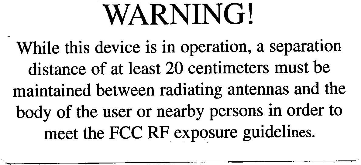
-----Original Message----- > From: [email protected] [mailto:[email protected]] > Sent: Thursday, August 10, 2000 9:35 AM > To: [email protected] > Subject: > > > To:Dale Albright, null > From:Frank Coperich > [email protected] > FCC Application Processing Branch > > Re:FCC ID BCR-RPT-MR741 > Applicant:Allen Telecom Systems > Correspondence Reference Number:15517 > 731 Confirmation Number:EA98004 > Date of Original E-Mail:08/10/2000 > > > RF exposure exhibit included a warning statement indicating a separation > distance of 20 cm for antenna installation. The separation distance for > MPE > compliance is dependent on antenna gain. Please estimate MPE distance > according to device output and maximum antenna gain allowed for uplink and > downlink operations. The antennas must be fix-mounted on permanent > structures to qualify for categorical exclusion requirements for fixed > transmitters. The appropriate antenna installation instructions should be > included in the manual for users and installers to satisfy RF exposure > compliance requirements. It should also be indicated in the manual that > the > requirements are for FCC RF exposure compliance. Please submit relevant > pages of the manual containing these instructions and indicate its > location > in the manual. Allen telecom response: To clarify the previuos response, The application of this repeater is intended to be used as an outdoor site with fixed pole mount or roof top antennas. We have corrected the above warning statement by add a new installer warning statement to the beginning of the users manual. This is to alert the installers that antenna placement must be within the FCC RF exposure guidelines. We have also clarified the intended use of the product in the introduction section. (please refer to the updated manual pages). > The items indicated above must be submitted before processing can continue > on the above referenced application. Failure to provide the requested > information within 60 days of the original e-mail date may result in > application dismissal pursuant to Section 2.917 (c) and forfeiture of the > filing fee pursuant to section 1.1108. > > DO NOT reply to this e-mail by using the Reply button. In order for your > response to be processed expeditiously, you must upload your response via > the Internet at www.fcc.gov, Electronic Filing, OET Equipment > Authorization > Electronic Filing. If the response is submitted through Add Attachments, > in order to expedite processing, a message which informs the processing staff > that a new exhibit has been submitted must also be submitted via Submit > Correspondence. Also, please note that partial responses increase > processing time and should not be submitted.
Test Report
FCC ID: BCR-RPT-MR741 33_EME/I Rev 4 Report Number: 0503ALL EUT: PCS1900 Channel Selective Repeater Model: MR741 Serial: None EMC CONFORMANCE REPORT FCC Title 47 CFR, Part 24 Subpart E testing for ManufacturerAllen Telecom Equipment NamePCS1900 Channel Selective Repeater Equipment ModelMR741 Report/Issue Date12 February, 2000 Report Number0503ALL FCC IDBCR-RPT-MR741 Prepared by Flextronics EMC Laboratories (formally EMC International, Inc.) 762 Park Avenue Youngsville, NC 27596 FCC ID: BCR-RPT-MR741 33_EME/I Rev 4 Report Number: 0503ALL EUT: PCS1900 Channel Selective Repeater Model: MR741 Serial: None Page 2 of 40 ManufacturerAllen Telecom 140 Vista Centre Drive Forest, VA 24551 USA 804-386-5350 Requester / ApplicantHoward Gianopulos Name of EquipmentPCS1900 Channel Selective Repeater Model No. MR741 Serial No. None Type of EquipmentPCS Amplifier Class of EquipmentNon-Residential (Class A) Application of Regulation(s)FCC Title 47 CFR Part 24 Subpart E RSP-100 Issue 7:1996 Application of Standard(s)ANSI C63.4:1992 RSS-131 Issue 1:1996 Date Received01 Feb. 2000Date Initiated01 Feb. 2000Date Completed17 Apr. 2000 The electromagnetic compatibility test and documented data described in this report has been performed and recorded by Flextronics EMC Laboratories, in accordance with the standards and procedures listed herein. As the responsible authorized agent, I hereby declare that the PCS1900 Channel Selective Repeater (Model No. MR741) has been shown to be capable of complying with the EMC requirements of the stated regulations and standards based on the results, special accessories and modifications listed in this report. This report must not be used by the client to claim product endorsement by NVLAP or any agency of the U.S. Government. This report contains data that are not covered by NVLAP accreditation. This report shall not be reproduced except in full, without the written approval of the laboratory. Dale AlbrightDate Director, EMC Operations NVLAP Signatory FCC ID: BCR-RPT-MR741 33_EME/I Rev 4 Report Number: 0503ALL EUT: PCS1900 Channel Selective Repeater Model: MR741 Serial: None Page 3 of 40 DIRECTORY 1.0 OVERVIEW 1.1INTRODUCTIONPAGE 1.1.1 Scope5 1.1.2 Purpose5 1.1.3 Summary6 1.2GENERAL INFORMATION 1.2.1 Product Description7 1.2.2 Test Facility7 1.2.3 Test Equipment7 1.2.4 Measurement Uncertainty8 1.2.5 Calibration Traceability8 1.3SYSTEM TEST CONFIGURATION 1.3.1 Equipment Configuration9 1.3.2 Operation Mode9 1.3.3 Special Accessories9 1.3.4 Equipment Modifications9 2.0 MEASUREMENTS AT THE ENCLOSURE PORT 2.1RADIATED SPURIOUS EMISSIONS 10 – 21 FCC ID: BCR-RPT-MR741 33_EME/I Rev 4 Report Number: 0503ALL EUT: PCS1900 Channel Selective Repeater Model: MR741 Serial: None Page 4 of 40 3.0 MEASUREMENTS AT THE ANTENNA OUTPUT PORT 3.1PASSBAND GAIN AND BANDWIDTH 22 – 24 3.2SIGNAL INTEGRITY 25 – 28 3.3OUTPUT POWER AND NON-LINEARITY 29 – 33 3.4INTERMODULATION 34 – 38 3.5CONDUCTED SPURIOUS EMISSIONS 39 – 41 Agent Letter Exhibit A Block Diagram Exhibit B External Photos Exhibit C Label and Location Exhibit D Internal Photos Exhibit E Operational Description Exhibit F Radiation Exposure Exhibit G Schematic Diagram Exhibit H Users Manual Exhibit I FCC ID: BCR-RPT-MR741 33_EME/I Rev 4 Report Number: 0503ALL EUT: PCS1900 Channel Selective Repeater Model: MR741 Serial: None Page 5 of 40 1.0 OVERVIEW 1.1INTRODUCTION 1.1.1 Scope This report is intended to document conformance with the requirements of the Federal Communications Commission and Industry Canada based on the results of testing performed on 01 Feb. 2000 through 17 Apr. 2000 on the PCS1900 Channel Selective Repeater Model No. MR741 manufactured by Allen Telecom. This report only applies to the specific samples tested under the stated test conditions. It is the responsibility of the manufacturer to assure that additional production units of this model are manufactured with identical or EMI equivalent electrical and mechanical components. This report is further intended to document changes and modifications to the EUT throughout it’s life cycle. All documentation will be included as a supplement. 1.1.2 Purpose Testing was performed to evaluate the EMC performance of the EUT and to submit the data for review and certification in accordance with the applicable requirements, procedures, and criteria defined in the application of regulations and standards listed in this report. FCC ID: BCR-RPT-MR741 33_EME/I Rev 4 Report Number: 0503ALL EUT: PCS1900 Channel Selective Repeater Model: MR741 Serial: None Page 6 of 40 1.1.3 Summary Test TypeGuidance Document RequirementsMeasuredResultPage FCC Part 24No greater than -13 dBm from 30 MHz to 20 GHz 48.0 dB under limit @ 300 MHzPass16Radiated Spurious Emissions RSS-131: 1996No greater than -13 dBm from 30 MHz to 10 GHz 48.0 dB under limit @ 300 MHzPass16 Passband GainRSS-131: 1996Passband gain shall not exceed nominal gain by more than 1 dB Uplink gain = 84.7 dB Downlink gain = 82.9 dB Pass24 20dB BandwidthRSS-131: 199620 dB bandwidth shall not exceed nominal bandwidth stated by manufacturer Uplink BW = 660 kHz Downlink BW = 680 kHz Pass24 Signal IntegrityFCC Part 24Device must not change quality of signal input Input Vs OutputPass27–28 Uplink (dBm)Downlink (dBm)Mean Output Power and Non-Linearity RSS-131: 1996Manufacturer rating must not exceed mean output power GSM = 35.9GSM = 35.8 Pass30 Uplink (dBm)Downlink (dBm)IntermodulationFCC Part 24 RSS-131: 1996 Intermodulation tone level no greater than –13 dBm GSM = -36.0GSM = -36.0 Pass33–36 FCC Part 24 RSS-131: 1996 No greater than -13 dBm from 30 MHz to 20 GHz Less than -24.0 dBmPass39Conducted Spurious Emissions FCC ID: BCR-RPT-MR741 33_EME/I Rev 4 Report Number: 0503ALL EUT: PCS1900 Channel Selective Repeater Model: MR741 Serial: None Page 7 of 40 1.2GENERAL INFORMATION 1.2.1 Product Description A description of the EUT and information for all equipment used in the tested system, including: descriptions of cables, clocks and input/output ports has been sup…
Text truncated - open the document above for the full version.
Contact Information
Applicant
Michael Shumate(Director, North American Operations)
Technical Contact
Allen Telecom SystemsHoward Gianopulos
[email protected]804-386-5242
762 Park Ave · Forest, North Carolina · United States
Test Firm
TUV Rheinland of North AmericaMichael Moranha
Technical Specifications
| # | Rule Parts | Frequency Range | Power Output | Emission |
|---|---|---|---|---|
| 2 | 24E | 1.93 GHz - 1.99 GHz | 3.8 W | GXW |
Other Applications from Andrew Wireless Innovations Group

BCR-IONEUAP
Mar 10, 2015ION-E
Equipment Class
B2I - Part 20 Industrial Booster (CMRS)
BCR-M17P26
Feb 08, 2012ION-M17P/26 EU
Equipment Class
TNB - Licensed Non-Broadcast Station Transmitter
BCR-TFAHUS717
Aug 14, 2011ION-B TFAH-US7/17
Equipment Class
TNB - Licensed Non-Broadcast Station Transmitter
BCR-TFAHUS4B
Jul 20, 2011ION-B TFAH-US4B
Equipment Class
PCB - PCS Licensed Transmitter
BCR-TFBM17
Jan 23, 2011ION-B TFBM17 FIBER OPTIC DISTRIBUTION REMOTE UNIT
Equipment Class
TNB - Licensed Non-Broadcast Station Transmitter