BCR-RPT-NCM843Non-Broadcast Booster
Andrew Wireless Innovations Group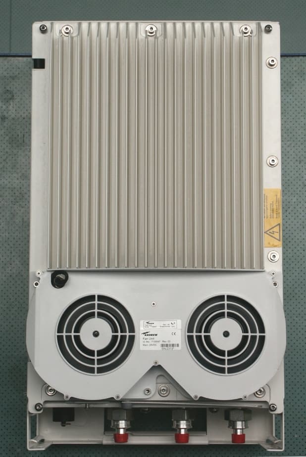
Click to zoom
Application Details
- Equipment Class
- TNB - Licensed Non-Broadcast Station Transmitter
- Date of Grant
- Oct 29, 2006
- Application Purpose
- Original Equipment
- Date of Application
- Oct 26, 2006
- Equipment Note
- Non-Broadcast Booster
- Frequency Range
- 869.00000000 - 894.00000000
- Country
- United States
Documents & Files
Document Text
Text extracted from the exhibit documents filed with the FCC. Open a document above to read the original.
Cover Letter(s)
1) Confidentiality Request: A letter is provided. • Schematics • Block diagram • Manual • Datasheet • Bill of Materials The block diagram and datasheet provided is part of the user installation manual, a document which is provided to the installer under a non-discloser agreement only. Although in a normal application a install manual is not allowed to be held confidential, in previous applications this applicant has shown that, since this document is controlled within the Andrew Corporation and is only provided to outside entities under a non- disclosure agreement, this document is eligible for confidentiality. 2) RF Exposure Classification: Fixed. RF Exposure is addressed at the time of licensing since the antenna is not defined until that point. a. The device is installed either on a pole or on the wall of a building. The device is always installed outdoors. In cases where the device is used to improve coverage inside a building, a separately approved in-building antenna distribution system is connected to the coverage side of the device. The rf exposure is addressed at the time of licensing. A warning in the manual informs the installer to observe rf exposure requirements as specified in the construction permit and operating license. 3) Explanation of model differences: There are two models for which approval is sought under the FCC ID. Number BCR-RPT-NCM843 Node C843 Node M843 These two models are electrically identical. The difference is that the Node C843 allows more filter options in the firmware to support the 1.23 MHz channels associated with IS- 95 CDMA, whereas Node M843 supports only 5 MHz channel filter settings (up to two 5 MHz channels) to accommodate W-CDMA. 4) Classification of the device per FCC Amplifier Interpretation document The device fits the definition of a “Booster” since it does not translate the frequency and is not used to extend the coverage of a Base Station. Booster is a device that automatically reradiates signals from base transmitters without channel translation, for the purpose of improving the reliability of existing service by increasing the signal strength in dead spots. An “in-building radiation system” is a signal booster. These devices are not intended to extend the size of coverage from the originating base station. A booster can be either single or multiple channels. The device does not operate as an “in-building radiation system” as defined by the interpretation document but can be connected to such a system that is separately approved. The device is in one enclosure and operates in the 800 MHz (non PCS) band thus it should be assigned the equipment class TNB. 5) Booster Rules: An exhibit entitled 22.383 Notification is included. This is correspondence sent to the applicant notifying them that the equipment must meet all of the requirements of 22.383. 6) Output Power: Power output listed on Form 731 is composite power. The device can operate either as a single carrier or multi-carrier device. Peak rf output power is +43 dBm(20watts) for a single carrier in the downlink direction and +23 dBm(200 mW) for a single carrier in the uplink direction. Each time a carrier is added, the rf power output is automatically reduced. If the number of carriers is doubled, the power per carrier is reduced by 3 dB. There are two modes of ALC (Automatic Level Control). - Maximum rf power - Fixed gain In the maximum rf power mode, the installer sets the desired maximum rf power output via password protected software. The maximum rf power levels above cannot be exceeded. The device monitors the rf output level and automatically increases or decreases rf gain to maintain the rf power level set by the installer. In the fixed gain mode the installer sets the desired gain using the same software as described above. The gain is maintained until the peak rf output power levels are reached (20 W Downlink, 200 mW Uplink). If these maximum output power levels are reached, the gain is automatically reduced to ensure that the peak authorized rf output levels are not exceeded. 7) Protection against saturation The device automatically disables the rf amplifier when a condition of saturation is detected. This was verified by experimentation.
Cover Letter(s)
Andrew Corporation 108 Rand Park Drive Garner, NC U.S.A. 27529 Tel: (919) 771-2570 Fax: (919) 771-2360 www.andrew.com 6 September 2006 Equipment Autorisation Division Federal Communications Commission 7435 Oakland Mills Road Columbia, MD 21046 FCC ID: BCR-RPT-NCM843 Product Name: Node C 843, Node M843 Request for Confidentiality Pursuant to Sections 0.457 and 0.459 of the commission’s rules, we hereby request that the following documents be held confidential: • Schematics • Block diagram • Manual • Datasheet • Bill of Materials These materials contain trade secrets and proprietary information and are not customarily released to the public. The public disclosure of this information might be harmful to the company and provide unjustified benefits to our competitors. The manual is only provided for use by trained technicians and is not available to the general user from Andrew’s website. Dated this 6 Day of September 20 06 By: Michael Williamson Signature Printed Title: Product Manager On behalf of : Andrew Corporation Telephone: (919) 771-2570 x223
Cover Letter(s)
Andrew Corporation 108 Rand Park Drive Garner, NC 27529 Tel: (919) 329-8941 Fax: (919) 329-8950 www.andrew.com 17 October, 2006 American Telecommunications Certification Body, Inc. 6731 Whittier Avenue Suite C110 McLean, VA 22101 To Whom It May Concern: NTS Laboratory is authorized to act on our behalf, until otherwise notified, for applications to American Telecommunications Certification Body, Inc. (ATCB). We certify that we are not subject to denial of federal benefits, that includes FCC benefits, pursuant to Section 5301 of the Anti-Drug Abuse Act of 1988, U.S.C. 862. Further, no party, as defined in 47 CFR 1.2002 (b) to the application is subject to denial of federal benefits, that includes FCC benefits. Thank you. Regards, Michael Williamson Product Manager Andrew Corporation
Cover Letter(s)
American Telecommunications Certification Body Inc. 6731 Whittier Ave, McLean, VA 22101 October 20, 2006 RE: FCC ID: BCR-RPT-NCM843_ATCB004170 Attention: Tom Tidwell I have a few comments on this Application. Please note that further comments may arise in response to answers provided to the questions below. 1. Please note that the report (page 6 and 12) states that the antenna is determined at the time of licensing. Please note that in-building amplifiers do not get licensed and operate in conjunction with the licensed base transmitter (22.383 “Licensees may install and operate in-building radiation systems without applying for authorization.”) This means that the max gain antenna must be specified in the documentation for certification as this directly affects MPE of the device. Please correct the test report pages to list the highest allowed gain antenna for use with the device. Please note that this antenna should be the same antenna as listed in the MPE report (i.e. a max antenna gain allowed of 21dBi). 2. Please note that in regards to item 1 above, the manual needs to provide rf exposure information for the installation of the device. The information also needs to include the maximum antenna gain shown in the MPE report (i.e. 21dBi). Please provide a manual that correctly identifies the rf exposure cautions for this in-building device. 3. Please note that when measuring band edge data the lowest res bw settings would be 1% of the OBW of the device. Please note that in the case of a 2 carrier signal this would be 30kHz. Please note that the plots on pages 45 show the use of a res BW of only 20kHz (i.e. 10kHz less than allowed). Please explain and correct as necessary. Please review the report for similar corrections that may be necessary. 4. Please note that at least 6 readings for spurious emissions is expected for FCC certification. While these may include the noise floor readings of harmonics, 6 readings should still be provided in the report. Please adjust the report to provide at least 6 spurious emissions readings. 5. Please note that the documentation indicates that the amplifier is intended for use with 3G phones (i.e. the brochure states operation for to “CDMA2000, to 1xRTT, to EV-Do and beyond.”). Please note that boosters are to be tested to each of the modulation schemes for which they are intended to be used. Please confirm that the input to the booster was tested using compliant 3G technology signals. Please provide data for CDMA2000, 1xRTT, 1xEV-Do and any other modulation scheme for which this device is to be used. Alternately, please explain and give justification as to why the CDMA input signal used meets the requirements to test all modulations applicable. Dennis Ward mailto:[email protected] The items indicated above must be submitted before processing can continue on the above referenced application. Failure to provide the requested information may result in application termination. Correspondence should be considered part of the permanent submission and may be viewed from the Internet after a Grant of Equipment Authorization is issued. Please do not respond to this correspondence using the email reply button. In order for your response to be processed expeditiously, you must submit your documents through the AmericanTCB.com website. Also, please note that partial responses increase processing time and should not be submitted. Any questions about the content of this correspondence should be directed to the sender.
Cover Letter(s)
American Telecommunications Certification Body Inc. 6731 Whittier Ave, McLean, VA 22101 October 20, 2006 RE:FCCID: BCR-RPT-NCM843_ATCB004170 Attention: Tom Tidwell I have a few comments on this Application. Please note that further comments may arise in response to answers provided to the questions below. 1. Please note that the report (page 6 and 12) states that the antenna is determined at the time of licensing. Please note that in-building amplifiers do not get licensed and operate in conjunction with the licensed base transmitter (22.383 “Licensees may install and operate in-building radiation systems without applying for authorization.”) This means that the max gain antenna must be specified in the documentation for certification as this directly affects MPE of the device. Please correct the test report pages to list the highest allowed gain antenna for use with the device. Please note that this antenna should be the same antenna as listed in the MPE report (i.e. a max antenna gain allowed of 21dBi). Please see revised report and a revised MPE to reflect maximum antenna gain of 17 dBi. The unit and its associated antennas are always mounted outdoors on a permanent structure. We have amended the Install Manual to advise a maximum antenna gain of 17 dBI and minimum separation distance of 4 meters. 2. Please note that in regards to item 1 above, the manual needs to provide rf exposure information for the installation of the device. The information also needs to include the maximum antenna gain shown in the MPE report (i.e. 21dBi). Please provide a manual that correctly identifies the rf exposure cautions for this in-building device. See response to #1 above 3. Please note that when measuring band edge data the lowest res bw settings would be 1% of the OBW of the device. Please note that in the case of a 2 carrier signal this would be 30kHz. Please note that the plots on pages 45 show the use of a res BW of only 20kHz (i.e. 10kHz less than allowed). Please explain and correct as necessary. Please review the report for similar corrections that may be necessary. In the past FCC has ruled that when multiple carriers are transmitted, the 1% relates to 1% of one carrier. The IS-95 CDMA carrier necessary bandwidth is 1.23 MHz thus the minimum RBW that could be used is 12 kHz. The reason given for this is that the emission measurement that is being made is the edge of the single carrier closest to the band edge and the inter-modulation product of the two carriers. The idea is that the RBW not be less than 1% of the bandwidth of the signal being measured (the 1.23 MHz wide inter-modulation product in this case). My client would like to get a ruling from FCC on this if you deem it necessary. 4. Please note that at least 6 readings for spurious emissions is expected for FCC certification. While these may include the noise floor readings of harmonics, 6 readings should still be provided in the report. Please adjust the report to provide at least 6 spurious emissions readings. Please see amended report with additional noise floor readings. 5. Please note that the documentation indicates that the amplifier is intended for use with 3G phones (i.e. the brochure states operation for to “CDMA2000, to 1xRTT, to EV-Do and beyond.”). Please note that boosters are to be tested to each of the modulation schemes for which they are intended to be used. Please confirm that the input to the booster was tested using compliant 3G technology signals. Please provide data for CDMA2000, 1xRTT, 1xEV-Do and any other modulation scheme for which this device is to be used. Alternately, please explain and give justification as to why the CDMA input signal used meets the requirements to test all modulations applicable. The brochure is a general marketing piece and refers to the capability of several models in addition to the Node C843 and Node M843. The Node C843 operates with IS-95 CDMA and the Node M843 operates with W-CDMA (referred to as UMTS in Europe) signals. The Node C was tested with an IS-95 signal as described on pages 16 and 17 of the test report. The Node M was tested with a W-CDMA signal as described on page 17 of the test report. The W-CDMA signal is a 3G signal. Because of the way the Node C and Node M detect the pilot of each of these signals, the system will only repeat these signals. Dennis Ward mailto:[email protected] The items indicated above must be submitted before processing can continue on the above referenced application. Failure to provide the requested information may result in application termination. Correspondence should be considered part of the permanent submission and may be viewed from the Internet after a Grant of Equipment Authorization is issued. Please do not respond to this correspondence using the email reply button. In order for your response to be processed expeditiously, you must submit your documents through the AmericanTCB.com website. Also, please note that partial responses increase processing time and should not be submitted. Any questions about the content of this correspondence should be directed to the sender.
RF Exposure Info
Prediction of Maximum Permissible Exposure Equation from page 18 of OET Bulletin 65, Edition 97-01 where: S = power density P = power input to the antenna G = directional power gain of the antenna relative to an isotropic radiator R = distance to the center of radiation of the antenna Max. peak output power at antenna terminal(dBm):43.00 Max. peak output power at antenna terminal(W):19.953 Antenna gain for prediction(dBi):17 Maximum antenna gain(numeric):50.118723 Duty Cycle(%):100 Prediction distance(cm):400 Prediction frequency(MHz):894 Limit for uncontrolled exposure(mw/cm²): 0.533 S(mw/cm²) = :0.497 2 4 PG S RΠ =
Test Report
This report and the information contained herein represent the results of testing test articles identified and selected by the client performed to specifications and/or procedures selected by the client. National Technical Systems (NTS) makes no representations, expressed or implied, that such testing is adequate (or inadequate) to demonstrate efficiency, performance, reliability, or any other characteristic of the articles being tested, or similar products. This report should not be relied upon as an endorsement or certification by NTS of the equipment tested, nor does it represent any statement whatsoever as to its merchantability or fitness of the test article, or similar products, for a particular purpose. This report shall not be reproduced except in full. NTS Plano, 1701 E. Plano Pkwy., Plano, TX 75074 Tel: (972) 509-2566, Fax: (972) 509-0073 Page 1 of 66 Certification Test Report CFR 47 FCC Part 2 and Part 22, Subpart C Model: Node C843, Node M843 FCC ID # BCR-RPT-NCM843 Project Code: W6337 Revision: 1 Prepared for: Andrew Corporation 108 Rand Park Drive Garner, North Carolina 27529 Author: Tom Tidwell, Manager of Wireless Services Issued: 24 October, 2006 1701 E. Plano Parkway, Suite 150 Plano, Texas 75074 Phone: (972) 509-2566 Fax: (972) 509-0073 Model: C843 / M843 Compliance Test Report FCC ID # BCR-RPT-NCM843 This report and the information contained herein represent the results of testing test articles identified and selected by the client performed to specifications and/or procedures selected by the client. National Technical Systems (NTS) makes no representations, expressed or implied, that such testing is adequate (or inadequate) to demonstrate efficiency, performance, reliability, or any other characteristic of the articles being tested, or similar products. This report should not be relied upon as an endorsement or certification by NTS of the equipment tested, nor does it represent any statement whatsoever as to its merchantability or fitness of the test article, or similar products, for a particular purpose. This report shall not be reproduced except in full. NTS Plano, 1701 E. Plano Pkwy., Plano, TX 75074 Tel: (972) 509-2566, Fax: (972) 509-0073 Page 2 of 66 Report Summary NTS Plano Accreditation Numbers: FCC: 101741 IC: 46405-4319 File # IC-4319 Applicant: Andrew Corporation 108 Rand Park Drive Garner, North Carolina 27529 Customer Representative: Michael Williamson EUT Description: EUT Description Manufacturer Model Revision Serial Number The EUT is an in-building repeater system designed to repeat both IS-95 CDMA and W-CDMA signals in the North American Cellular band (824- 869 MHz, 869-894 MHz) Andrew Wireless Systems Gmbh Node C 843 IS-95 Node M 843 W-CDMA 2 11 Variations in models: The Node C843 and Node M843 are electrically identical devices. The software mode options for channel filter settings are reduced to two 5 MHz channels on the Node M843 model to accommodate up to two W-CDMA carriers, while the Node C843 allows additional channel filter settings for single 1.23 MHz channels for IS-95 CDMA. Model: C843 / M843 Compliance Test Report FCC ID # BCR-RPT-NCM843 This report and the information contained herein represent the results of testing test articles identified and selected by the client performed to specifications and/or procedures selected by the client. National Technical Systems (NTS) makes no representations, expressed or implied, that such testing is adequate (or inadequate) to demonstrate efficiency, performance, reliability, or any other characteristic of the articles being tested, or similar products. This report should not be relied upon as an endorsement or certification by NTS of the equipment tested, nor does it represent any statement whatsoever as to its merchantability or fitness of the test article, or similar products, for a particular purpose. This report shall not be reproduced except in full. NTS Plano, 1701 E. Plano Pkwy., Plano, TX 75074 Tel: (972) 509-2566, Fax: (972) 509-0073 Page 3 of 66 Test Summary Deviations from: Appendix Test/Requirement Description Base Standard Test Basis NTS Procedure Pass / Fail Applicable Rule Parts A RF Power Output No No No PASS CFR 47, Part 2, Para. 2.1046 CFR 47, Part 90, Para. 90.205 B Modulation Characteristics No No No PASS CFR 47, Part 2, Para. 2.1047 CFR 47, Part 90, Para. 90.207 C Occupied Bandwidth No No No PASS CFR 47, Part 2, Para. 2.1049 CFR 47, Part 90, Para. 90.210 D Spurious Emissions at Antenna Terminals No No No PASS CFR 47, Part 2, Para. 2.1051 CFR 47, Part 90, Para. 90.210 E Field Strength of Spurious Radiation No No No PASS CFR 47, Part 2, Para. 2.1053 CFR 47, Part 90, Para. 90.210 F Frequency Stability No No No PASS CFR 47, Part 2, Para. 2.1055 CFR 47, Part 90, Para. 90.213 Test Result: The product presented for testing complied with test requirements as shown above. This is to certify that the preceding report is true and correct to the best of my knowledge. Robert Stevens, Tom Tidwell, Quality Assurance Manager Wireless Test Engineer Model: C843 / M843 Compliance Test Report FCC ID # BCR-RPT-NCM843 This report and the information contained herein represent the results of testing test articles identified and selected by the client performed to specifications and/or procedures selected by the client. National Technical Systems (NTS) makes no representations, expressed or implied, that such testing is adequate (or inadequate) to demonstrate efficiency, performance, reliability, or any other characteristic of the articles being tested, or similar products. This report should not be relied upon as an endorsement or certification by NTS of the equipment tested, nor does it represent any statement whatsoever as to its merchantability or fitness of the test article, or similar products, for a particular purpose. This report shall not be reproduced except in full. NTS Plano, 1701 E. Plano Pkwy., Plano, TX 75074 Tel: (972) 509-2566, Fax: (972) 509-0073 Page 4 of 66 Table of Contents REPORT…
Text truncated - open the document above for the full version.
Contact Information
Applicant
Michael Shumate(Director, North American Operations)
Technical Specifications
| # | Rule Parts | Frequency Range | Power Output | Emission | Tolerance |
|---|---|---|---|---|---|
| 2 | 22H | 869 MHz - 894 MHz | 19.45 W | F9W | Amp |
Other Applications from Andrew Wireless Innovations Group

BCR-IONEUAP
Mar 10, 2015ION-E
Equipment Class
B2I - Part 20 Industrial Booster (CMRS)
BCR-M17P26
Feb 08, 2012ION-M17P/26 EU
Equipment Class
TNB - Licensed Non-Broadcast Station Transmitter
BCR-TFAHUS717
Aug 14, 2011ION-B TFAH-US7/17
Equipment Class
TNB - Licensed Non-Broadcast Station Transmitter
BCR-TFAHUS4B
Jul 20, 2011ION-B TFAH-US4B
Equipment Class
PCB - PCS Licensed Transmitter
BCR-TFBM17
Jan 23, 2011ION-B TFBM17 FIBER OPTIC DISTRIBUTION REMOTE UNIT
Equipment Class
TNB - Licensed Non-Broadcast Station Transmitter