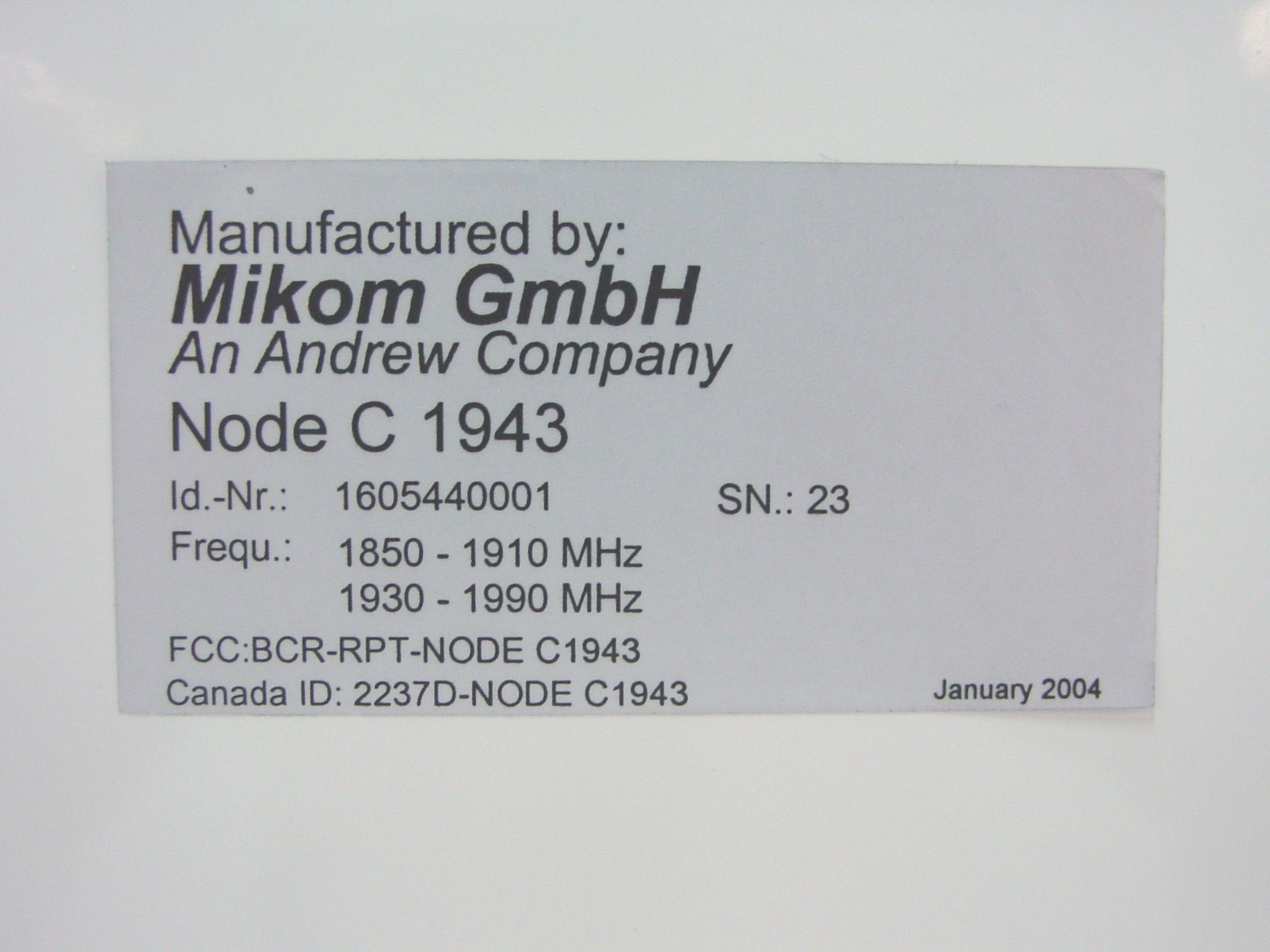
BCR-RPT-NODEC1943Broadband PCS Repeater
Andrew Wireless Innovations Group
Click to zoom
Application Details
- Equipment Class
- AMP - Amplifier
- Date of Grant
- Mar 16, 2004
- Application Purpose
- Original Equipment
- Date of Application
- Mar 16, 2004
- Equipment Note
- Broadband PCS Repeater
- Frequency Range
- 1850.75000000 - 1909.35000000
- Country
- United States
Documents & Files
Document Text
Text extracted from the exhibit documents filed with the FCC. Open a document above to read the original.
Users Manual
ID No: 161692 PRELIMINARY Page 1 User’s Manual for Node C Prototype Network Elements with Interface Unit User’s Manual for Node C Network Elements Page 2 PRELIMINARY M0121A1A_uc.doc © Copyright 2003 Mikom GmbH All rights reserved. All information contained in this manual has been revised thoroughly. Yet Mikom An Andrew Company accepts no liability for any omissions or faults. Mikom An Andrew Company reserves the right to change all hard- and software characteristics without notice. Names of products mentioned herein are used for identification purposes only and may be trademarks and/or registered trademarks of their respective companies. No parts of this publication may be reproduced, stored in a retrieval system, transmitted in any form or by any means, electronical, mechanical photocopying, recording or otherwise, without prior written permission of the publisher. Mikom GmbH An Andrew Company, 27-November-2003 ID No: 161692 PRELIMINARY Page 3 TABLE OF CONTENTS 1 GENERAL 7 1.1 ABBREVIATIONS 7 1.2 HEALTH AND SAFETY WARNINGS 8 1.3 PREAMBLE 9 1.4 INTERNATIONAL CONTACT ADDRESSES 10 2 INTRODUCTION 11 2.1 PURPOSE 11 2.2 THE NODE C NETWORK ELEMENT 11 2.3 QUICK START CHECKLIST 12 3 INSTALLATION 13 3.1 MECHANICAL INSTALLATION 13 3.1.1 General 13 3.1.2 Wall Mounting Procedure 14 3.1.3 Connection Option 16 3.1.4 Pole Mounting Procedures 17 3.2 ELECTRICAL INSTALLATION 20 3.2.1 General 20 3.2.2 Grounding 21 3.2.3 Power Connection 22 3.2.4 Connection of the Antenna Cables 23 3.2.5 Connection of Cable Bridge 23 3.2.6 Connections for Optional Equipment 24 4 COMMISSIONING 25 4.1 GENERAL 25 4.2 SOFTWARE SETUP 26 4.2.1 Remote Control 26 4.2.2 Connection Devices 26 4.2.3 Connection Procedures 26 4.2.3.1 Setup Overview 26 4.2.3.2 Installing the USB driver 27 4.2.3.3 Direct connection for Windows XP 28 4.2.3.4 Modem connection for Windows XP 38 4.2.3.5 Direct connection for Windows 2000 48 4.2.3.6 Accessing the web page 60 4.2.4 Main Menus of the Web Page 61 4.2.4.1 Setup Wizard 61 4.2.4.2 Connectivity and Upload 63 4.2.4.3 Technician Setup 64 4.2.4.4 Alarm Management 65 4.3 TROUBLESHOOTING 66 User’s Manual for Node C Network Elements Page 4 PRELIMINARY M0121A1A_uc.doc 5 FUNCTIONAL DESCRIPTION 69 5.1 GENERAL 69 5.2 FEATURES OF THE NODE C 72 5.2.1 Filters 72 5.2.2 Digital ICE (Digital Interference Cancellation Equipment) 72 5.2.3 VSWR (Voltage Standing Wave Ratio) 73 5.2.4 RSSI (Receive Signal Strength Indication) 73 5.2.5 Alarmforwarding 73 5.2.6 External Alarms 74 5.2.7 Summary Alarm 75 5.3 COMPONENTS OF THE NODE C AND INTERFACE UNIT 76 5.3.1 Duplexer 76 5.3.2 RF and DC Distribution Unit 78 5.3.3 Digital Channel Module (DCM) 79 5.3.4 Uplink Final Amplifier 80 5.3.5 Downlink Final Amplifier 80 5.3.6 Distribution & Alarm Board 82 5.3.7 Power Supply 83 5.4 OPTIONAL EQUIPMENT 83 5.4.1 Modem with Battery Backup 83 5.4.1.1 Initstrings 84 5.4.1.2 Wireless Modem 84 5.4.1.3 Battery Backup 85 5.4.2 PSU Redundancy 86 5.4.3 High Rejection Filter 86 6 MAINTENANCE 87 6.1 GENERAL 87 6.2 REPLACEMENT OF COMPONENTS 87 6.2.1 Power Supply 88 6.2.2 Modem 89 6.2.3 Battery Backup 90 7 APPENDIX 91 7.1 ILLUSTRATIONS 91 7.1.1 Cabinet Drawings 91 7.1.2 Layout 93 7.2 SPECIFICATIONS 96 7.2.1 Electrical Specifications 96 7.2.2 Mechanical Specifications 98 7.2.3 Specifications for Optional Equipment 98 7.3 PARTSLISTS 99 7.3.1 Interface Unit 99 7.3.2 Node C 100 8 INDEX 101 ID No: 161692 PRELIMINARY Page 5 FIGURES AND TABLES figure 3-1 Positions of drilling holes .......................................................................... 14 figure 3-2 Wall mounting procedure.......................................................................... 15 figure 3-3 Connection option..................................................................................... 16 figure 3-4 Cabinet combining kit ............................................................................... 16 figure 3-5 Pole mounted systems ............................................................................. 17 figure 3-6 Back-to-back pole mounting ..................................................................... 18 figure 3-7 Pole mounting two systems ...................................................................... 19 figure 3-8 Grounding bolts ........................................................................................ 21 figure 3-9 Grounding a system ................................................................................. 21 figure 3-10 Power supply plug .................................................................................. 22 figure 3-11 Mains connector ..................................................................................... 22 figure 3-12 Front view of antenna connections ......................................................... 23 figure 3-13 Connector panel of the Node C.............................................................. 24 figure 3-14 Connector panel of the Interface Unit ..................................................... 24 figure 4-1 Front and top cover screws ...................................................................... 25 figure 4-2 Position of mains power switch................................................................. 25 figure 4-3 USB and null modem cable connection.................................................... 27 figure 4-4 Home page of web interface..................................................................... 60 figure 4-5 Setup Wizard ............................................................................................ 61 figure 4-6 Connectivity and Upload menu................................................................. 63 figure 4-7 Technician Setup menu............................................................................ 64 figure 4-8 Alarm Management menu........................................................................ 65 figure 5-1 DC block diagram of a Node C .........................................................…
Text truncated - open the document above for the full version.
Block Diagram
C:\Ready_To_Convert\Doc\405749.DOC Page 1 of 1 17.03.04 Node C 19xx - DC Blockdiagram
Block Diagram
C:\Ready_To_Convert\Doc\405750.DOC Page 1 of 1 17.03.04 Node C 19xx - RF Blockdiagram
Cover Letter(s)
Node-C 19xx TCB Questions Item 1. Per 2.1033(c)(6) Please supply a description of the means provided for varying the power output. Please describe how the maximum power output is set within the device. -- The users manual provided is not sufficiently clear with respect to this purpose and is not a suitable substitute. Answer: The unit has two different modes of operation. In the power mode the output power of the Node C is controlled in order to keep the pilot power at the output of the Node C forward link constant. In the gain mode the gain of both paths is kept constant. In both cases the maximum output power is limited to the max. average power capabilities of the PA. An ALC circuit in the DCM is used together with a calibrated gain value for the following stages will limit the max. average power out of the Node C. Item 2. Per 2.1033(c)(13), please provide a detailed description of the modulation circuitry and filters as described in the users manual. -- The users manual describes the use of filter sets to block or use specific channel bands (see section 5.2.1 in users manual), no information was provided with this filing regarding filter characteristics or responses. Please provide. Answer: No modulation is applied to the incoming signal. The filter characteristics exhibit a rejection of 40dBc at a frequency offset of ±1.25MHz from the edges of the passband.
Cover Letter(s)
Item 1. Since the Allen Telecom has changed ownership to Andrew Wireless, a new CKC CS General Agreement is required prior to completion of application processing. Please provide an updated singed copy of the CKC CS general agreement. ANS: Nemko has signed a General Agreement and we have a POA with Andrew and it has been uploaded. This binds Andrew to the terms of the CKCCS General Agreement. The company name is Andrew Corporation, the division we are directly in contact with is the Wireless Divisions Group. Item 2. The Grantee Information has changed since the last filing for this applicant. Please provide the complete updated details so that the form 731 may reflect the correct applicant, including legal business name, contact person, phone and fax numbers. ANS: All information on the 731 in regards to Andrew Corporation is correct. Item 3. The applicant’s FRN Number is not listed on the form 731. Please provide the correct FRN number for this applicant. ANS: The FRN number is 0007784689. This represents the Corporate Office of Andrew Corporation in IL. Item 4. Since the letter requesting confidentiality is not on company letterhead, and the person signing the letter is not listed on the grantee information on the FCC website, a new letter of confidentiality will be required. Please provide a confidentiality letter on letterhead, or have the person named on the FCC website sign the letter. ANS: The letter was signed by an authorized person from Andrew Corporation. The letter does not need to be on Company letterhead, nor does the authorized person have to be the same individual named on the FCC site. Item 5. The form 731 is missing the required agent information on line 16, please state whether the information from line 14 can be used for this item. ANS: Line 16 lists Tom Tidwell, his information in located on the 731 form and can be used. Item 6. Please provide a tune-up procedure ANS: Uploaded Item 7. Please provide a test report ANS: Uploaded Item 8. Please provide test setup photos ANS: Uploaded Item 9. Per 2.1033(c)(6) Please supply a description of the means provided for varying the power output. Please describe how the maximum power output is set within the device. ANS: Tune up procedure in users manual. Item 10. Per 2.1033(c)(8) Please supply the DC voltages applied to and DC currents into several elements of the final RF amplifier stage of the equipment. ANS: Please refer to the Block Diagram, it has voltages and currents. Item 11. Please supply a photo or drawing indicating label placement. ANS: This information is located in the Label exhibit already provided. Item 12. Per 2.1033(c)(13), please provide a detailed description of the modulation circuitry and filters as described in the users manual. ANS: The device is a repeater, there is no modulation circuitry, what goes in, comes out. Item 13. Power output is listed on form 731 is in dBm for the first entry; do the same units apply to the next entry? Please provide RF Power output listing in Watts. ANS: Convert. 43dBm = 20W and 23dBm = 0.2W (200mW)
Cover Letter(s)
From: [email protected] Sent: Thursday, March 11, 2004 12:25 PM To: [email protected] Subject: Responses The FCC ID number is as listed on the latest label: BCR-RPT-NODEC1943 A revided test report has been uploaded to correct the FCC ID number. Intermod proceedure is listed in the back of the test report.
Operational Description
Node-C1943 RF Enhancer Large Area Coverage, Capacity, and High Speed Data for 1900 MHz CDMA Now designers of 1900 MHz CDMA systems can get an RF enhancer with intelligence and performance. The Andrew Node-C1943 is an RF enhancer for CDMA systems with up to 15 MHz of adjacent spectrum. This primary network element is ideal for the first phase of the network rollout and for any subsequent phase where cost, coverage, and quality need to be optimized. Although the Node-C1943’s primary function is to increase signal strength between a mobile and a base station in areas where high-quality voice or high-speed data service is not available, it also enhances air-interface capacity and increases the network data rate. The Node-C1943 is a dedicated CDMA device. It requires no additional hardware upgrades as a network migrates from J-STD-8 to CDMA2000 1X and beyond. The programmable radio may be upgraded locally through a USB based web connection or remotely via a wireless modem, and the modem may be circuit switch or packet data based. This provides the network management system with on-demand, alarm generated, or heartbeat monitoring via the always-connected packet features. Features and functions may be locally or remotely monitored and changed via a web browser. In addition, Andrew provides a dedicated OMC and has implemented a standard SNMP based MIB that can easily integrate into any 3rd party OMC platform. The graphical browser provides an intuitive setup menu, including a wizard that allows users, regardless of skill level, to correctly setup the equipment without any additional equipment. The Node-C1943 is self-diagnosing, self-adaptive, and virtually maintenance free. It is designed to provide more than 10 years of service under virtually any condition. •One man lift form factor •Auto wizard setup for easy installation •Digital filtering •Uniform phase and magnitude amplification •Automatic interference cancellation •Decreased isolation requirements •Virtual measurement equipment •CDMA quality diagnostics •SNMP and web-based GUI Connecting the Wireless World An excellent choice for any area, from the urban core to the rural highway. product specifications Maximum gain . . . . . . . . . . . . . . . . . . . . . . . . .103 dB (automatic setting) Gain adjust range . . . . . . . . . . . . . . . . . . . . . .53 dB to 103 dB Return loss . . . . . . . . . . . . . . . . . . . . . . . . . . . . .>15 dB Uplink diversity . . . . . . . . . . . . . . . . . . . . . . . . .Standard Spectral emission mask, dBc . . . . . . . . . . . .-45 @ 750 kHz . . . . . . . . . . . . . . . . . . . . . . . . . . . . . . . . . . . . . . .-60 @ 1.98 MHz Out of band gain (rejection), dB . . . . . . . . . . . . . . . . . . . . . . . . . . . . . .Option 1: .Gain -40 in 750 kHz . . . . . . . . . . . . . . . . . . . . . . . . . . . . . .Option 2: .Gain -70 in 750 kHz Modulation accuracy . . . . . . . . . . . . . . . . . . .RHO > 0.96 Spurious emissions . . . . . . . . . . . . . . . . . . . . .-13 dBm Far off selectivity (ultimate rejection) . . . .70 dB Power supply . . . . . . . . . . . . . . . . . .Standard: .110 Vac/40-60 Hz . . . . . . . . . . . . . . . . . . . . . . . . . . . . . .Optional: .36-72 Vdc Power consumption, watts . . . . . . . . . . . . . .430 idle . . . . . . . . . . . . . . . . . . . . . . . . . . . . . . . . . . . . . . .610 full output power RF connectors . . . . . . . . . . . . . . . . .Standard: .7-16 DIN female . . . . . . . . . . . . . . . . . . . . . . . . . . . . . .Optional: .N female Weatherproofing . . . . . . . . . . . . . . . . . . . . . . .IP 55 Temperature range . . . . . . . . . . . . . . . . . . . . .-33°C to +50°C Specifications for Node-C1943 RF Enhancer Electrical Frequency, MHz . . . . . . . . . . . . . . . .Uplink: . . .1850-1910 . . . . . . . . . . . . . . . . . . . . . . . . . . . . . .Downlink: .1930-1990 CDMA carriers . . . . . . . . . . . . . . . . .Option 1: .1-11 adjacent (per module), . . . . . . . . . . . . . . . . . . . . . . . . . . . . . . . . . . . . . . .1.23 MHz carriers . . . . . . . . . . . . . . . . . . . . . . . . . . . . . .Option 2: .1-3 adjacent (per module), . . . . . . . . . . . . . . . . . . . . . . . . . . . . . . . . . . . . . . .5 MHz carriers Maximum downlink output power, dBm . .+43.0 (1 CDMA carrier) . . . . . . . . . . . . . . . . . . . . . . . . . . . . . . . . . . . . . . .+40.0 (2 CDMA carriers) . . . . . . . . . . . . . . . . . . . . . . . . . . . . . . . . . . . . . . .+37.0 (4 CDMA carriers) Maximum uplink composite output power . . . . . . . . . . . . . . . . . . . . . . . . . . . . . . . . .+23 dBm Output power step size . . . . . . . . . . . . . . . . .1 dB Output power accuracy over all conditions . . . . . . . . . . . . . . . . . . . . . . . . . . . . .±1.5 dB Minimum downlink input power at full output power . . . . . . . . . . . . . . . . . . . .-60 dBm Maximum input power without damage .+10 dBm Minimum antenna isolation for maximum gain . . . . . . . . . . . . . . . . . . . . . .83 dB minimum Uplink noise figure over all gain conditions . . . . . . . . . . . . . . . . . . . . . . . . . . . . .3.5 dB Delay, μs . . . . . . . . . . . . . . . . . . . . .Option 1: .< 5.7 . . . . . . . . . . . . . . . . . . . . . . . . . . . . . .Option 2: .< 8.0 Cooling . . . . . . . . . . . . . . . . . . . . . . .twin redundant fans Acoustic noise, dBA . . . . . . . . . . . .47 @ 25°C . . . . . . . . . . . . . . . . . . . . . . . . . . . . . .55 @ 50°C Mechanical Height, width, depth, in (mm) . . .Node-C1943Interface Unit . . . . . . . . . . . . . . . . . . . . . . . . . . . . .21.5 x 12.5 x 10.2521.5 x 7.5 x 10.25 . . . . . . . . . . . . . . . . . . . . . . . . . . . . . .(546 x 320 x 260)(546 x 190 x 260) Weight, lb (kg) . . . . . . . . . . . . . . . . .Node-C1943Interface Unit . . . . . . . . . . . . . . . . . . . . . . . . . . . . . .55 (25)29 (13) Node-C1943 Interface Unit product specifications Features Items measured . . . . . . . . . . . . . . . . . . .…
Text truncated - open the document above for the full version.
Operational Description
C:\Ready_To_Convert\Doc\405758.DOC Page 1 of 1 17.03.04 General functional description Node C 19xx The Node C is designed to amplify signals between multiple UEs and a Base Tranceiver Station in a CDMA system. The unit consists of a filter and amplifier chain in the downlink and one or two filters and amplifier chains in the uplink (primary and diversity). The uplink and downlink paths are connected via a duplexer on both ends of each path. In the primary uplink path, a signal originating from the UE is separated from the downlink signal via the primary UL IN duplexer. It is then amplified by an integrated low noise amplifier (LNA) and forwarded to the uplink Digital Channel Module (DCM). The DCM down-converts the signal to base-band, digitally filters it, amplifies it and then up-converts it. In addition the interference cancellation technology is implemented in the DCM. Finally, the signal is sent to the final amplifier and combined with the downlink input signal in the DL IN duplexer. The optional diversity uplink path (via a second filter) is identical except signals enter via the diversity UL IN duplexer and are combined in the DCM with the primary path. In the downlink path, a signal originating from the Base Tranceiver Station is separated from the uplink signal in the DL IN duplexer. It is then amplified by an integrated low noise amplifier (LNA) and forwarded to the downlink digital channel module (DCM). The DCM down-converts the signal to base-band, digitally filters it amplifies it and then up-converts it. In addition the interference cancellation technology is implemented in the DCM. Finally, the signal is sent to the final amplifier and combined with the uplink input signal in the primary UL IN duplexer. The downlink DCM is also responsible for communication and control of the entire unit.
Parts List/Tune Up Info
ID No: 161692 PRELIMINARY Page 1 User’s Manual for Node C Prototype Network Elements with Interface Unit User’s Manual for Node C Network Elements Page 2 PRELIMINARY M0121A1A_uc.doc © Copyright 2003 Mikom GmbH All rights reserved. All information contained in this manual has been revised thoroughly. Yet Mikom An Andrew Company accepts no liability for any omissions or faults. Mikom An Andrew Company reserves the right to change all hard- and software characteristics without notice. Names of products mentioned herein are used for identification purposes only and may be trademarks and/or registered trademarks of their respective companies. No parts of this publication may be reproduced, stored in a retrieval system, transmitted in any form or by any means, electronical, mechanical photocopying, recording or otherwise, without prior written permission of the publisher. Mikom GmbH An Andrew Company, 27-November-2003 ID No: 161692 PRELIMINARY Page 3 TABLE OF CONTENTS 1 GENERAL 7 1.1 ABBREVIATIONS 7 1.2 HEALTH AND SAFETY WARNINGS 8 1.3 PREAMBLE 9 1.4 INTERNATIONAL CONTACT ADDRESSES 10 2 INTRODUCTION 11 2.1 PURPOSE 11 2.2 THE NODE C NETWORK ELEMENT 11 2.3 QUICK START CHECKLIST 12 3 INSTALLATION 13 3.1 MECHANICAL INSTALLATION 13 3.1.1 General 13 3.1.2 Wall Mounting Procedure 14 3.1.3 Connection Option 16 3.1.4 Pole Mounting Procedures 17 3.2 ELECTRICAL INSTALLATION 20 3.2.1 General 20 3.2.2 Grounding 21 3.2.3 Power Connection 22 3.2.4 Connection of the Antenna Cables 23 3.2.5 Connection of Cable Bridge 23 3.2.6 Connections for Optional Equipment 24 4 COMMISSIONING 25 4.1 GENERAL 25 4.2 SOFTWARE SETUP 26 4.2.1 Remote Control 26 4.2.2 Connection Devices 26 4.2.3 Connection Procedures 26 4.2.3.1 Setup Overview 26 4.2.3.2 Installing the USB driver 27 4.2.3.3 Direct connection for Windows XP 28 4.2.3.4 Modem connection for Windows XP 38 4.2.3.5 Direct connection for Windows 2000 48 4.2.3.6 Accessing the web page 60 4.2.4 Main Menus of the Web Page 61 4.2.4.1 Setup Wizard 61 4.2.4.2 Connectivity and Upload 63 4.2.4.3 Technician Setup 64 4.2.4.4 Alarm Management 65 4.3 TROUBLESHOOTING 66 User’s Manual for Node C Network Elements Page 4 PRELIMINARY M0121A1A_uc.doc 5 FUNCTIONAL DESCRIPTION 69 5.1 GENERAL 69 5.2 FEATURES OF THE NODE C 72 5.2.1 Filters 72 5.2.2 Digital ICE (Digital Interference Cancellation Equipment) 72 5.2.3 VSWR (Voltage Standing Wave Ratio) 73 5.2.4 RSSI (Receive Signal Strength Indication) 73 5.2.5 Alarmforwarding 73 5.2.6 External Alarms 74 5.2.7 Summary Alarm 75 5.3 COMPONENTS OF THE NODE C AND INTERFACE UNIT 76 5.3.1 Duplexer 76 5.3.2 RF and DC Distribution Unit 78 5.3.3 Digital Channel Module (DCM) 79 5.3.4 Uplink Final Amplifier 80 5.3.5 Downlink Final Amplifier 80 5.3.6 Distribution & Alarm Board 82 5.3.7 Power Supply 83 5.4 OPTIONAL EQUIPMENT 83 5.4.1 Modem with Battery Backup 83 5.4.1.1 Initstrings 84 5.4.1.2 Wireless Modem 84 5.4.1.3 Battery Backup 85 5.4.2 PSU Redundancy 86 5.4.3 High Rejection Filter 86 6 MAINTENANCE 87 6.1 GENERAL 87 6.2 REPLACEMENT OF COMPONENTS 87 6.2.1 Power Supply 88 6.2.2 Modem 89 6.2.3 Battery Backup 90 7 APPENDIX 91 7.1 ILLUSTRATIONS 91 7.1.1 Cabinet Drawings 91 7.1.2 Layout 93 7.2 SPECIFICATIONS 96 7.2.1 Electrical Specifications 96 7.2.2 Mechanical Specifications 98 7.2.3 Specifications for Optional Equipment 98 7.3 PARTSLISTS 99 7.3.1 Interface Unit 99 7.3.2 Node C 100 8 INDEX 101 ID No: 161692 PRELIMINARY Page 5 FIGURES AND TABLES figure 3-1 Positions of drilling holes .......................................................................... 14 figure 3-2 Wall mounting procedure.......................................................................... 15 figure 3-3 Connection option..................................................................................... 16 figure 3-4 Cabinet combining kit ............................................................................... 16 figure 3-5 Pole mounted systems ............................................................................. 17 figure 3-6 Back-to-back pole mounting ..................................................................... 18 figure 3-7 Pole mounting two systems ...................................................................... 19 figure 3-8 Grounding bolts ........................................................................................ 21 figure 3-9 Grounding a system ................................................................................. 21 figure 3-10 Power supply plug .................................................................................. 22 figure 3-11 Mains connector ..................................................................................... 22 figure 3-12 Front view of antenna connections ......................................................... 23 figure 3-13 Connector panel of the Node C.............................................................. 24 figure 3-14 Connector panel of the Interface Unit ..................................................... 24 figure 4-1 Front and top cover screws ...................................................................... 25 figure 4-2 Position of mains power switch................................................................. 25 figure 4-3 USB and null modem cable connection.................................................... 27 figure 4-4 Home page of web interface..................................................................... 60 figure 4-5 Setup Wizard ............................................................................................ 61 figure 4-6 Connectivity and Upload menu................................................................. 63 figure 4-7 Technician Setup menu............................................................................ 64 figure 4-8 Alarm Management menu........................................................................ 65 figure 5-1 DC block diagram of a Node C .........................................................…
Text truncated - open the document above for the full version.
Test Report
Nemko Test Report No.: 3L0496RUS1 Applicant: Andrew Corporation Equipment Under Test: Node C 1943 FCC ID: BCR-RPT-NODEC1943 In Accordance With: FCC Part 24, Subpart E Broadband PCS Repeaters Tested By: Nemko Dallas Inc. 802 N. Kealy Lewisville, Texas 75057-3136 Authorized By: Tom Tidwell, Frontline Manager Date: 3/11/04 Total Number of Pages: 44 Nemko Dallas FCC PART 24, SUBPART E BROADBAND PCS REPEATERS EQUIPMENT: PCS Repeater FCC ID: BCR-RPT-NODEC1943 PROJECT NO.: 3L0496 Page 2 of 44 Table of Contents Section 1. Summary of Test Results..................................................................3 Section 2. General Equipment Specification......................................................5 Section 3. RF Power Output.............................................................................8 Section 3. RF Power Output.............................................................................9 Section 4. Occupied Bandwidth......................................................................10 Section 5. Spurious Emissions at Antenna Terminals......................................15 Section 6. Field Strength of Spurious..............................................................29 Section 7. Frequency Stability.........................................................................32 Section 8. Test Equipment List.......................................................................33 ANNEX A - TEST DETAILS.............................................................................34 ANNEX B - TEST DIAGRAMS.........................................................................41 Nemko Dallas FCC PART 24, SUBPART E BROADBAND PCS REPEATERS EQUIPMENT: PCS Repeater FCC ID: BCR-RPT-NODEC1943 PROJECT NO.: 3L0496 Page 3 of 44 Section 1. Summary of Test Results Manufacturer: Andrew Corporation Model No.: Node C 1943 Serial No.: 13 General: All measurements are traceable to national standards. These tests were conducted on a sample of the equipment for the purpose of demonstrating compliance with FCC Part 24, Subpart E. New Submission Production Unit Class II Permissive Change Pre-Production Unit THIS TEST REPORT RELATES ONLY TO THE ITEM(S) TESTED. THE FOLLOWING DEVIATIONS FROM, ADDITIONS TO, OR EXCLUSIONS FROM THE TEST SPECIFICATIONS HAVE BEEN MADE. See “ Summary of Test Data”. Nemko Dallas Inc. authorizes the above named company to reproduce this report provided it is reproduced in its entirety and for use by the company’s employees only. Any use which a third party makes of this report, or any reliance on or decisions to be made based on it, are the responsibility of such third parties. Nemko Dallas Inc. accepts no responsibility for damages, if any, suffered by any third party as a result of decisions made or actions based on this report. This report applies only to the items tested. Nemko Dallas FCC PART 24, SUBPART E BROADBAND PCS REPEATERS EQUIPMENT: PCS Repeater FCC ID: BCR-RPT-NODEC1943 PROJECT NO.: 3L0496 Page 4 of 44 Summary Of Test Data NAME OF TEST PARA. NO. SPEC. MEAS. RESULT RF Power Output 24.232 100W 17.82W Complies Occupied Bandwidth (CDMA) 24.238 Input/Output Complies Complies Spurious Emissions at Antenna Terminals 24.238(a) -13 dBm Complies Complies Field Strength of Spurious Emissions 24.238(a) -13 dBm E.I.R.P. Complies Complies Frequency Stability 24.235 NA NA Footnotes: (1) Modulation characteristics were not tested since the E.U.T. processes but does not produce a modulated waveform. Measurement uncertainty for each test configuration is expressed to 95% probability. Nemko Dallas FCC PART 24, SUBPART E BROADBAND PCS REPEATERS EQUIPMENT: PCS Repeater FCC ID: BCR-RPT-NODEC1943 PROJECT NO.: 3L0496 Page 5 of 44 Section 2. General Equipment Specification Supply Voltage Input: 120 VAC Frequency Bands: Downlink: Block A : 1930 – 1945 MHz Block D : 1945 – 1950 MHz Block B : 1950 – 1965 MHz Block E : 1965 – 1970 MHz Block F : 1970 – 1975 MHz Block C : 1975 – 1990 MHz Frequency Range: 1930.75 – 1989.35 MHz Frequency Bands: Uplink: Block A : 1850 – 1865 MHz Block B : 1865 – 1870 MHz Block C : 1870 – 1885 MHz Block D : 1885 – 1890 MHz Block E : 1890 – 1895 MHz Block F : 1895 – 1910 MHz Frequency Range: 1850.75 – 1909.35 MHz CDMA GSM NADC (F9W) (GXW) (DXW) Type of Modulation and Designator: System Gain: 103dB Downlink 83dB Uplink Output Impedance: 50 ohms Max Input: -60 dBm +23 dBm RF Output (Rated): Uplink +43 dBm 1 CDMA Carrier RF Output (Rated): Downlink +37 dBm 4 CDMA Carriers F1-F1 F1-F2 N/A Frequency Translation: Band Selection: Software Duplexer Fullband Nemko Dallas FCC PART 24, SUBPART E BROADBAND PCS REPEATERS EQUIPMENT: PCS Repeater FCC ID: BCR-RPT-NODEC1943 PROJECT NO.: 3L0496 Page 6 of 44 Modifications Made During Testing No modifications made. Nemko Dallas FCC PART 24, SUBPART E BROADBAND PCS REPEATERS EQUIPMENT: PCS Repeater FCC ID: BCR-RPT-NODEC1943 PROJECT NO.: 3L0496 Page 7 of 44 Description of Operation The Node C is designed to amplify signals between multiple UEs and a Base Tranceiver Station in a CDMA system. The unit consists of a filter and amplifier chain in the downlink and one or two filters and amplifier chains in the uplink (primary and diversity). The uplink and downlink paths …
Text truncated - open the document above for the full version.
Contact Information
Applicant
Michael Shumate(Director, North American Operations)
Technical Contact
Non-Technical Contact
Nemko Dallas, Inc.Tom Tidwell
[email protected]972-436-9600
Test Firm
Nemko USA, Inc.Tom Tidwell
Technical Specifications
| # | Rule Parts | Frequency Range | Power Output | Emission | Tolerance |
|---|---|---|---|---|---|
| 2 | 24 | 1.85 GHz - 1.91 GHz | 200.00 mW | F9W | Amp |
Other Applications from Andrew Wireless Innovations Group

BCR-IONEUAP
Mar 10, 2015ION-E
Equipment Class
B2I - Part 20 Industrial Booster (CMRS)
BCR-M17P26
Feb 08, 2012ION-M17P/26 EU
Equipment Class
TNB - Licensed Non-Broadcast Station Transmitter
BCR-TFAHUS717
Aug 14, 2011ION-B TFAH-US7/17
Equipment Class
TNB - Licensed Non-Broadcast Station Transmitter
BCR-TFAHUS4B
Jul 20, 2011ION-B TFAH-US4B
Equipment Class
PCB - PCS Licensed Transmitter
BCR-TFBM17
Jan 23, 2011ION-B TFBM17 FIBER OPTIC DISTRIBUTION REMOTE UNIT
Equipment Class
TNB - Licensed Non-Broadcast Station Transmitter