BCR-RPT-NODEC843Cellular Repeater
Andrew Wireless Innovations Group
Click to zoom
Application Details
- Equipment Class
- TNB - Licensed Non-Broadcast Station Transmitter
- Date of Grant
- May 23, 2004
- Application Purpose
- Original Equipment
- Date of Application
- May 23, 2004
- Equipment Note
- Cellular Repeater
- Frequency Range
- 824.00000000 - 849.00000000
- Country
- United States
Documents & Files
Document Text
Text extracted from the exhibit documents filed with the FCC. Open a document above to read the original.
Users Manual
ID No: 161692 PRELIMINARY Page 1 User’s Manual for Node C Prototype Network Elements with Interface Unit User’s Manual for Node C Network Elements Page 2 M0121A1A_uc.doc © Copyright 2004 Mikom GmbH All rights reserved. All information contained in this manual has been revised thoroughly. Yet Mikom An Andrew Company accepts no liability for any omissions or faults. Mikom An Andrew Company reserves the right to change all hard- and software characteristics without notice. Names of products mentioned herein are used for identification purposes only and may be trademarks and/or registered trademarks of their respective companies. No parts of this publication may be reproduced, stored in a retrieval system, transmitted in any form or by any means, electronical, mechanical photocopying, recording or otherwise, without prior written permission of the publisher. Mikom GmbH An Andrew Company, 16-February-2004 ID No: 161692 PRELIMINARY Page 3 TABLE OF CONTENTS 1 GENERAL 7 1.1 ABBREVIATIONS 7 1.2 HEALTH AND SAFETY WARNINGS 8 1.3 PREAMBLE 9 1.4 INTERNATIONAL CONTACT ADDRESSES 10 2 INTRODUCTION 11 2.1 PURPOSE 11 2.2 THE NODE C NETWORK ELEMENT 11 2.3 QUICK START CHECKLIST 12 3 INSTALLATION 13 3.1 MECHANICAL INSTALLATION 13 3.1.1 General 13 3.1.2 Wall Mounting Procedure 14 3.1.3 Connection Option 16 3.1.4 Pole Mounting Procedures 17 3.2 ELECTRICAL INSTALLATION 20 3.2.1 General 20 3.2.2 Grounding 21 3.2.3 Power Connection 22 3.2.4 Connection of the Antenna Cables 23 3.2.5 Connection of Cable Bridge 23 3.2.6 Connections for Optional Equipment 24 4 COMMISSIONING 25 4.1 GENERAL 25 4.2 SOFTWARE SETUP 26 4.2.1 Remote Control 26 4.2.2 Connection Devices 26 4.2.3 Connection Procedures 26 4.2.3.1 Setup Overview 26 4.2.3.2 Installing the USB driver 27 4.2.3.3 Direct connection for Windows XP 28 4.2.3.4 Modem connection for Windows XP 38 4.2.3.5 Direct connection for Windows 2000 48 4.2.3.6 Accessing the web page 60 4.2.4 Main Menus of the Web Page 61 4.2.4.1 Setup Wizard 61 4.2.4.2 Connectivity and Upload 63 4.2.4.3 Technician Setup 64 4.2.4.4 Alarm Management 65 4.3 TROUBLESHOOTING 66 User’s Manual for Node C Network Elements Page 4 M0121A1A_uc.doc 5 FUNCTIONAL DESCRIPTION 69 5.1 GENERAL 69 5.2 FEATURES OF THE NODE C 72 5.2.1 Filters 72 5.2.2 Digital ICE (Digital Interference Cancellation Equipment) 72 5.2.3 VSWR (Voltage Standing Wave Ratio) 73 5.2.4 RSSI (Receive Signal Strength Indication) 73 5.2.5 Alarmforwarding 73 5.2.6 External Alarms 74 5.2.7 Summary Alarm 75 5.3 COMPONENTS OF THE NODE C AND INTERFACE UNIT 76 5.3.1 Duplexer 76 5.3.2 RF and DC Distribution Unit 78 5.3.3 Digital Channel Module (DCM) 79 5.3.4 Uplink Final Amplifier 80 5.3.5 Downlink Final Amplifier 80 5.3.6 Distribution & Alarm Board 82 5.3.7 Power Supply 83 5.4 OPTIONAL EQUIPMENT 83 5.4.1 Modem with Battery Backup 83 5.4.1.1 Initstrings 84 5.4.1.2 Wireless Modem 84 5.4.1.3 Battery Backup 85 5.4.2 PSU Redundancy 86 5.4.3 High Rejection Filter 86 6 MAINTENANCE 87 6.1 GENERAL 87 6.2 REPLACEMENT OF COMPONENTS 87 6.2.1 Power Supply 88 6.2.2 Battery Backup 89 6.2.3 Fan Unit 89 6.2.4 Modem 90 7 APPENDIX 91 7.1 ILLUSTRATIONS 91 7.1.1 Cabinet Drawings 91 7.1.2 Layout 93 7.2 SPECIFICATIONS 96 7.2.1 Electrical Specifications 96 7.2.2 Mechanical Specifications 98 7.2.3 Specifications for Optional Equipment 98 7.3 PARTSLISTS 99 7.3.1 Interface Unit 99 7.3.2 Node C 100 8 INDEX 101 ID No: 161692 PRELIMINARY Page 5 FIGURES AND TABLES figure 3-1 Positions of drilling holes........................................................................................14 figure 3-2 Wall mounting procedure .......................................................................................15 figure 3-3 Connection option ..................................................................................................16 figure 3-4 Cabinet combining kit.............................................................................................16 figure 3-5 Pole mounted systems...........................................................................................17 figure 3-6 Back-to-back pole mounting...................................................................................18 figure 3-7 Pole mounting two systems ...................................................................................19 figure 3-8 Grounding bolts......................................................................................................21 figure 3-9 Grounding a system ...............................................................................................21 figure 3-10 Power supply plug................................................................................................22 figure 3-11 Mains connector...................................................................................................22 figure 3-12 Front view of antenna connections ......................................................................23 figure 3-13 Connector panel of the Node C............................................................................24 figure 3-14 Connector panel of the Interface Unit ..................................................................24 figure 4-1 Front and top cover screws ....................................................................................25 figure 4-2 Position of mains power switch ..............................................................................25 figure 4-3 USB and null modem cable connection .................................................................27 figure 4-4 Home page of web interface ..................................................................................60 figure 4-5 Setup Wizard..........................................................................................................61 figure 4-6 Connectivity and Upload menu ..............................................................................63 figure 4-7 Technician Setup menu .........................................…
Text truncated - open the document above for the full version.
Block Diagram
C:\Ready_To_Convert\Doc\424939.DOC Page 1 of 1 24.05.04 Node C 8xx - DC Blockdiagram
Block Diagram
C:\Ready_To_Convert\Doc\424940.DOC Page 1 of 1 24.05.04 Node C 8xx - RF Blockdiagram
Cover Letter(s)
From: [email protected] Sent: Thursday, May 20, 2004 12:46 PM To: [email protected] Subject: Responses 1) They were provided, "DC Block Diagram" 2) Yes, the device is the same. It is missing the cooling fins/fans cover. 3) The block diagram is the same for the 8XX and 19XX, however a new diagram has been uploaded. 4) An updated report has been provided
Internal Photos
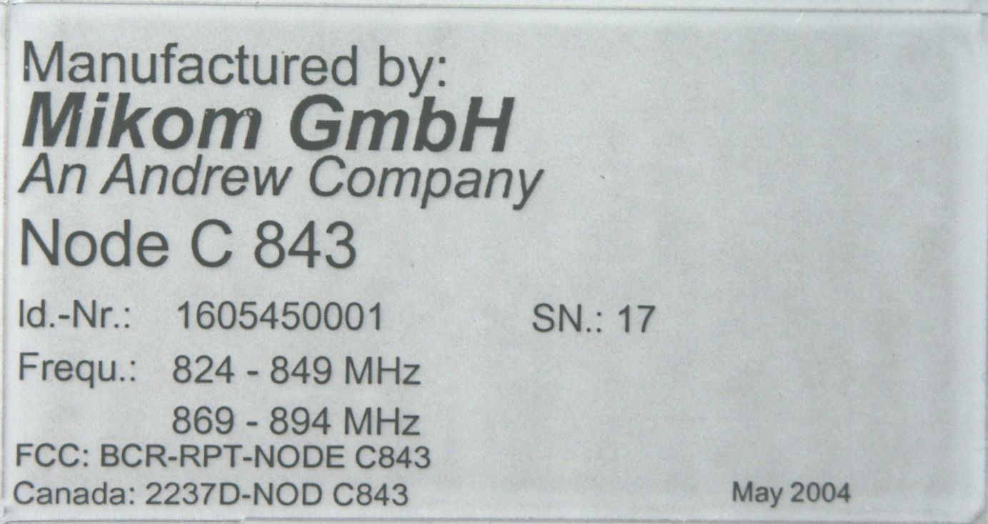
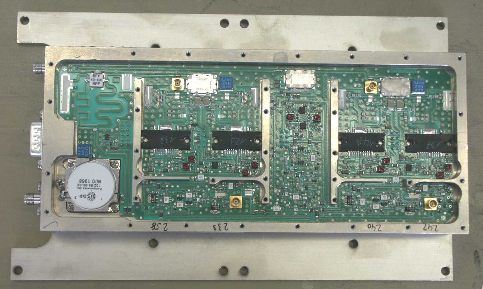
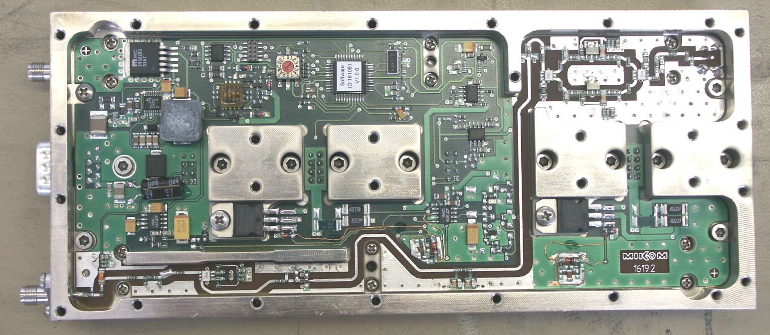
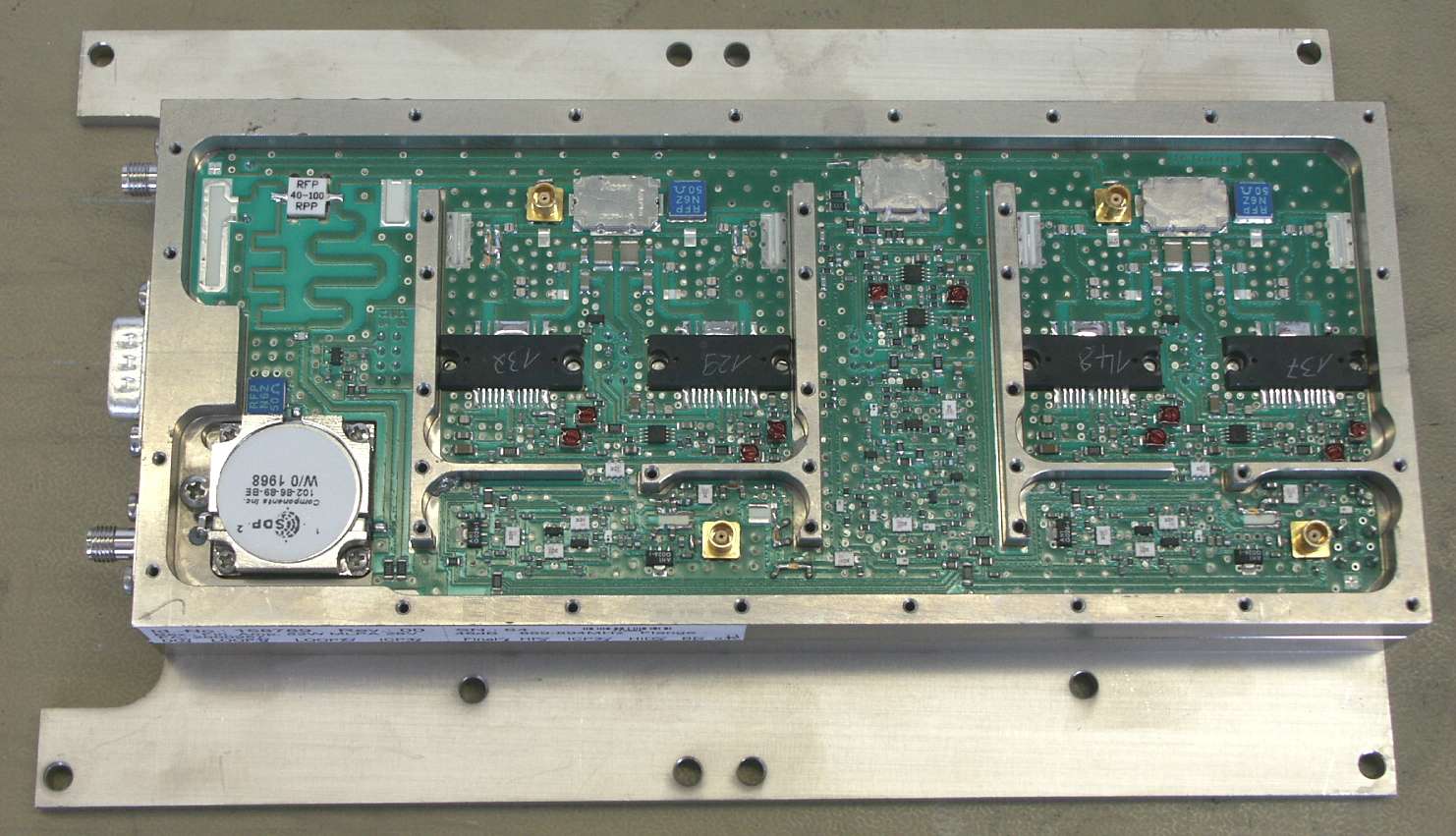
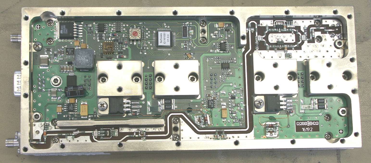
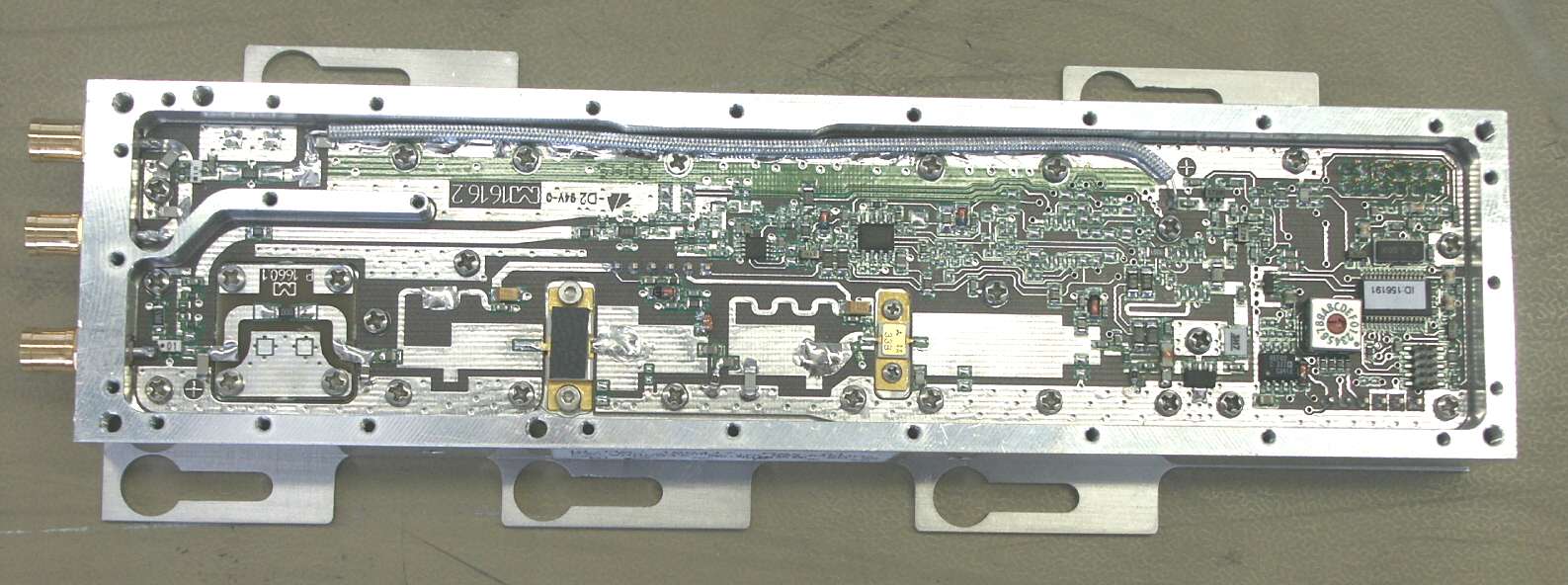
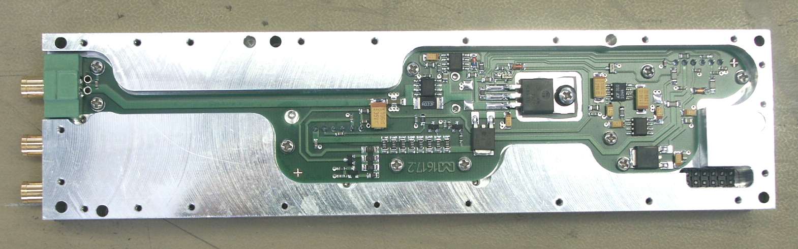
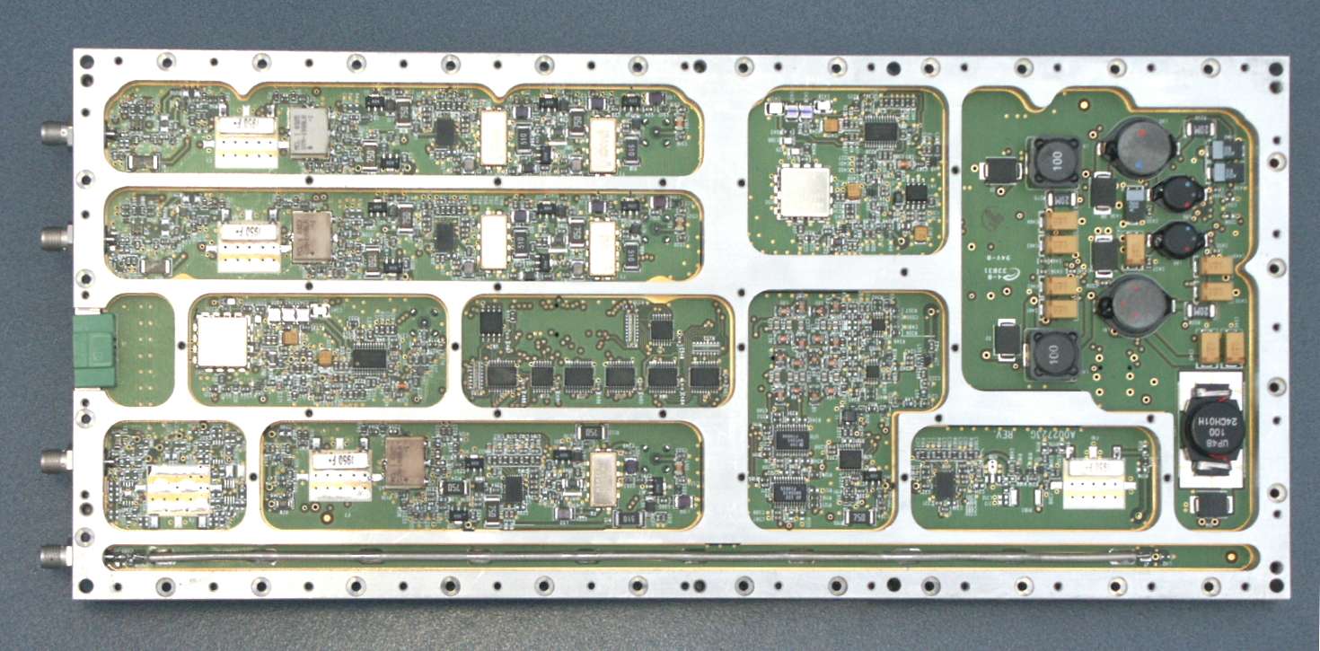
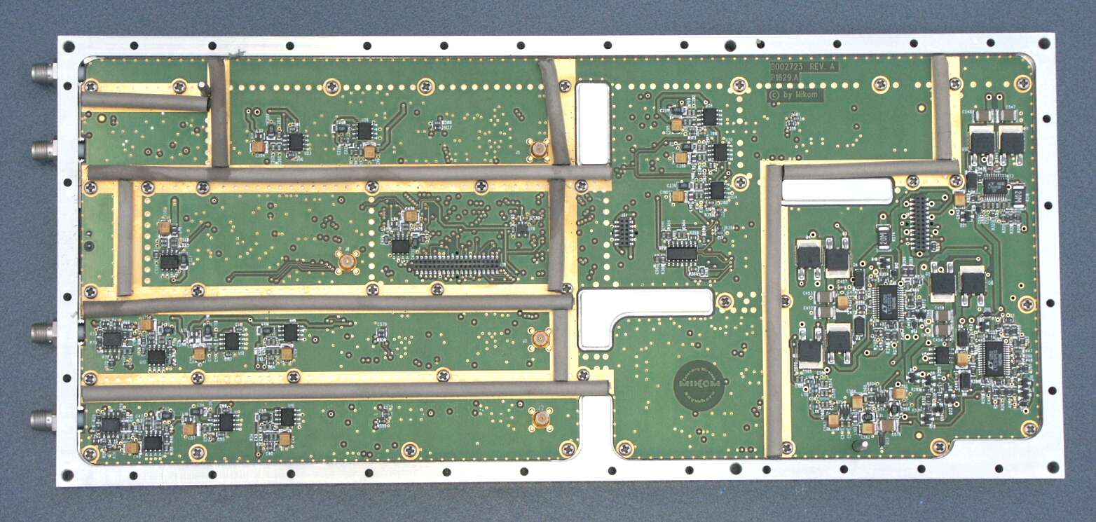
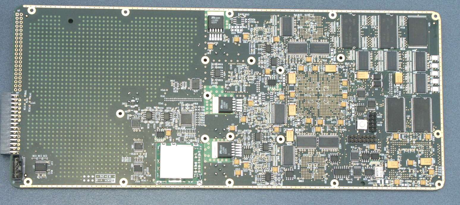
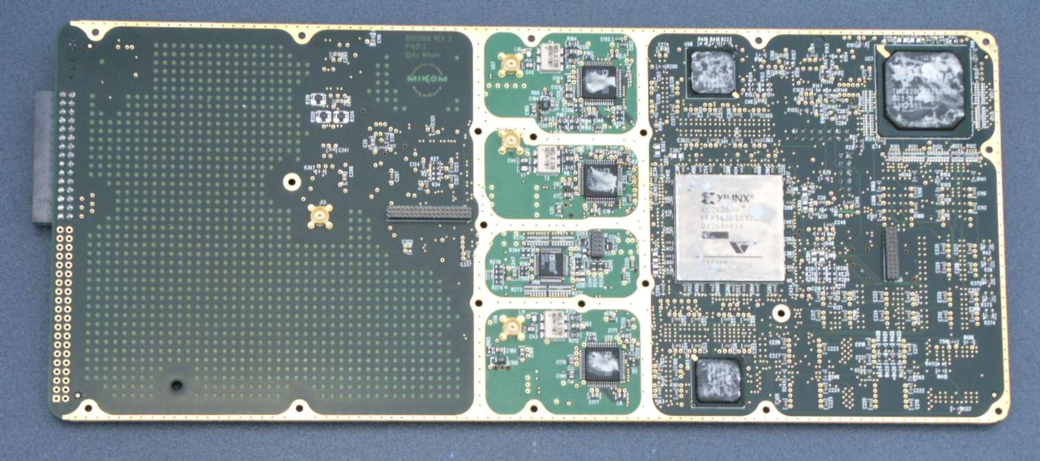
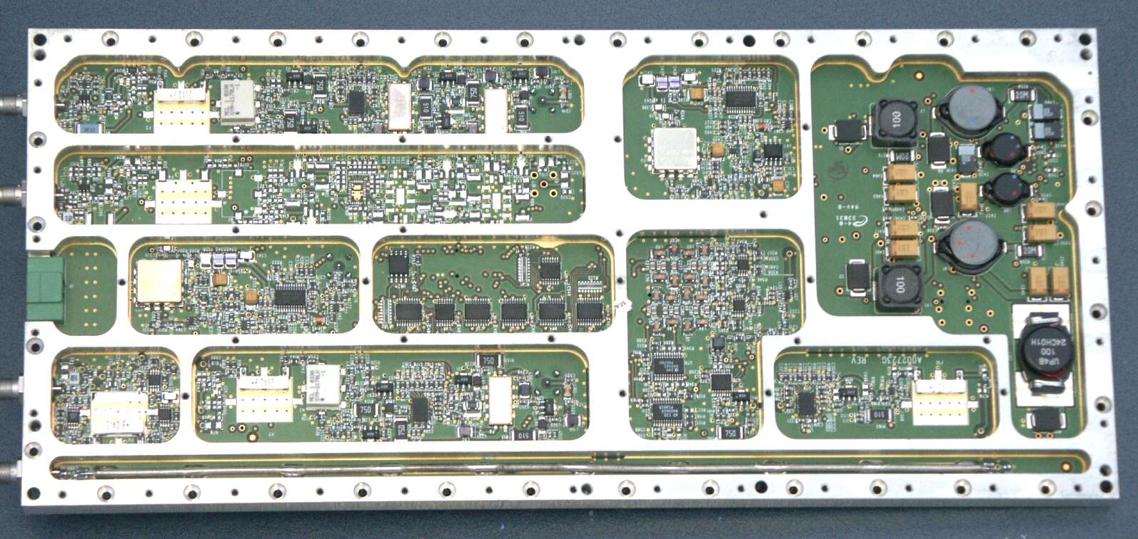
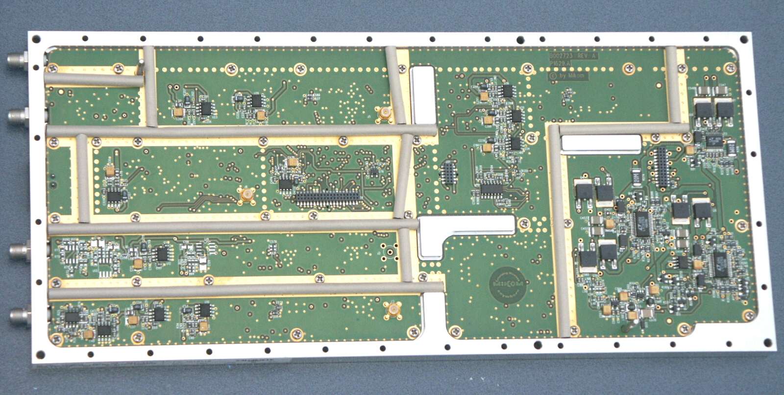
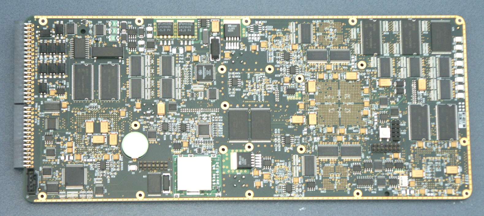
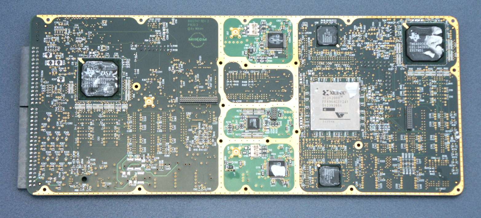
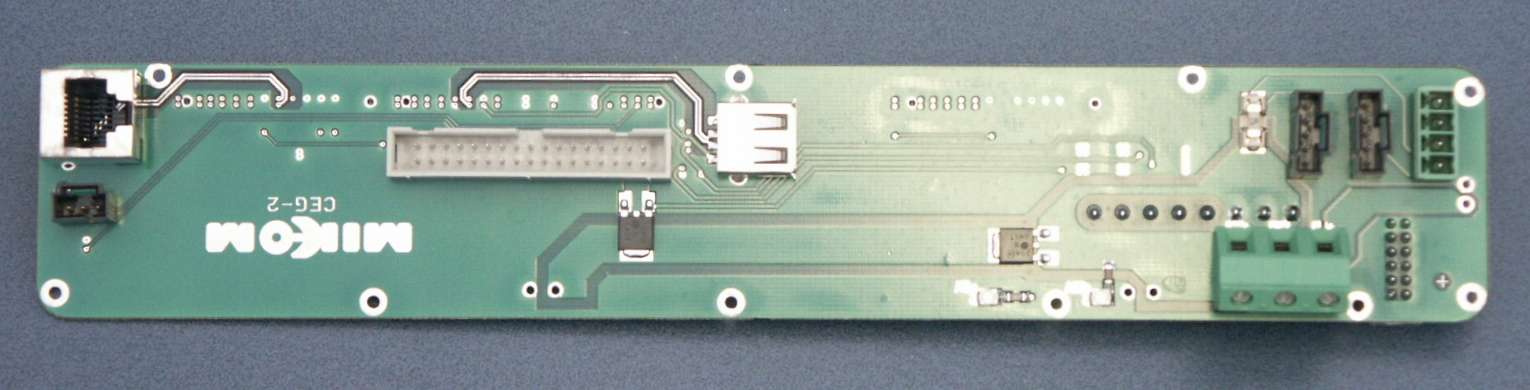
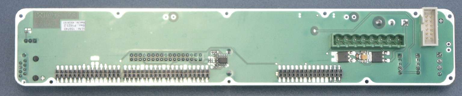
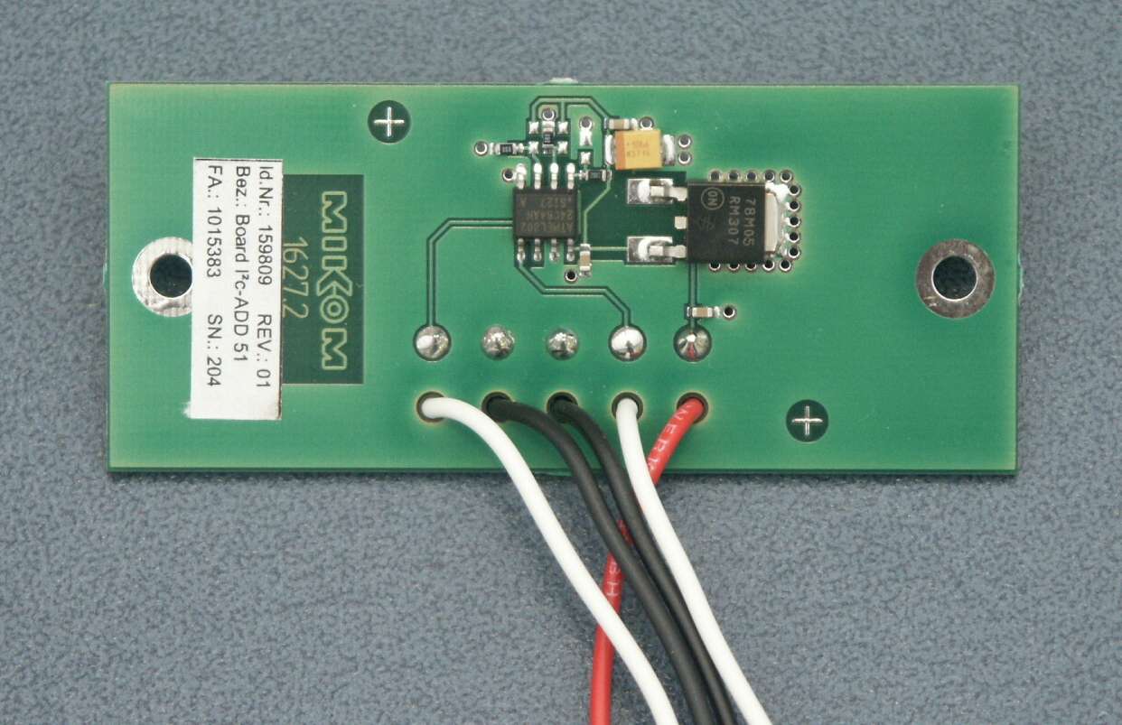
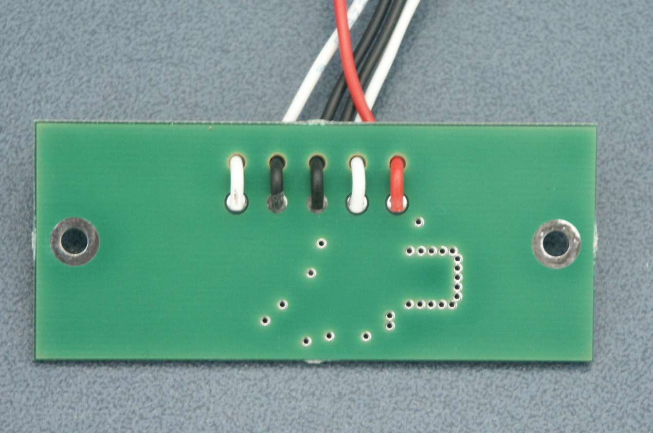
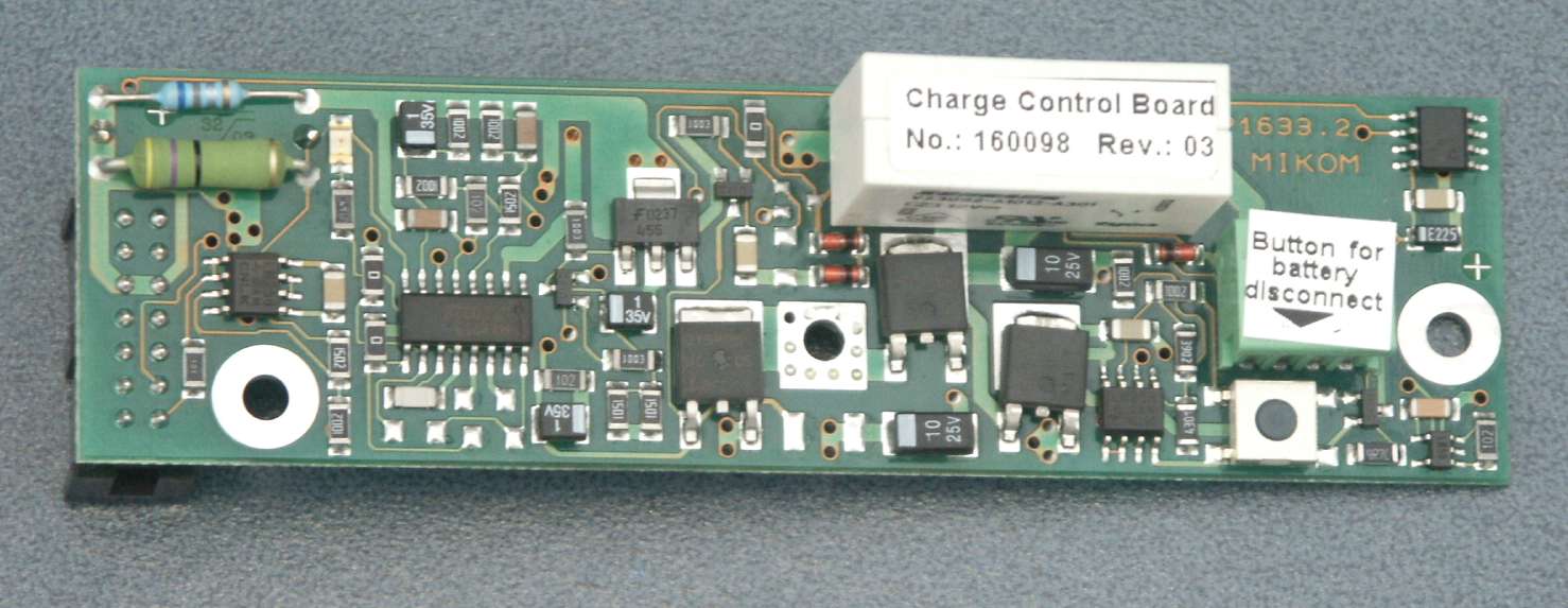
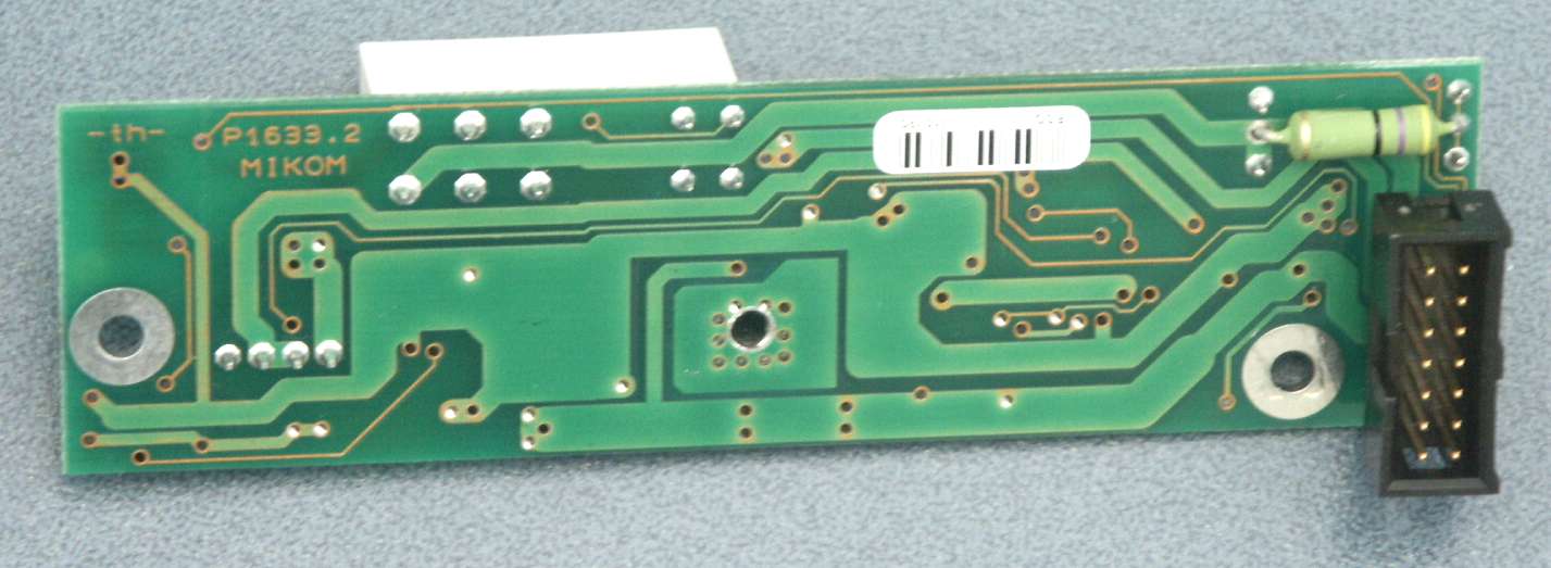
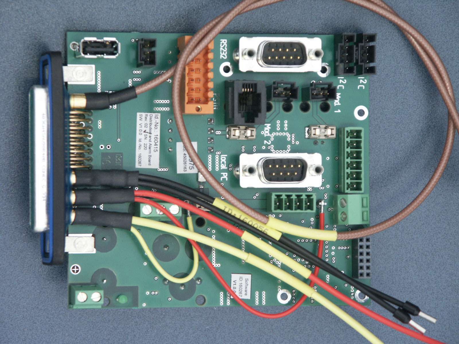
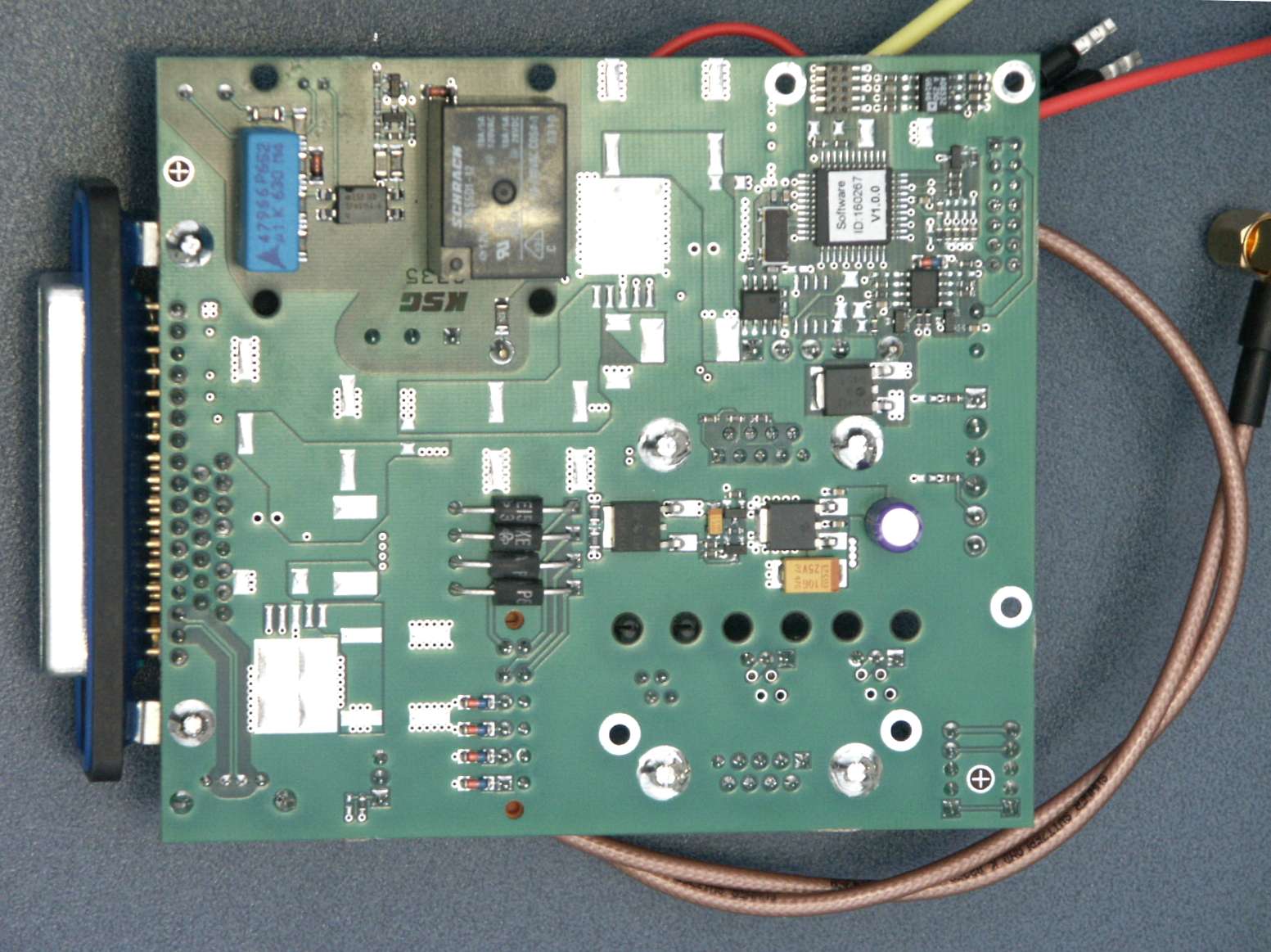
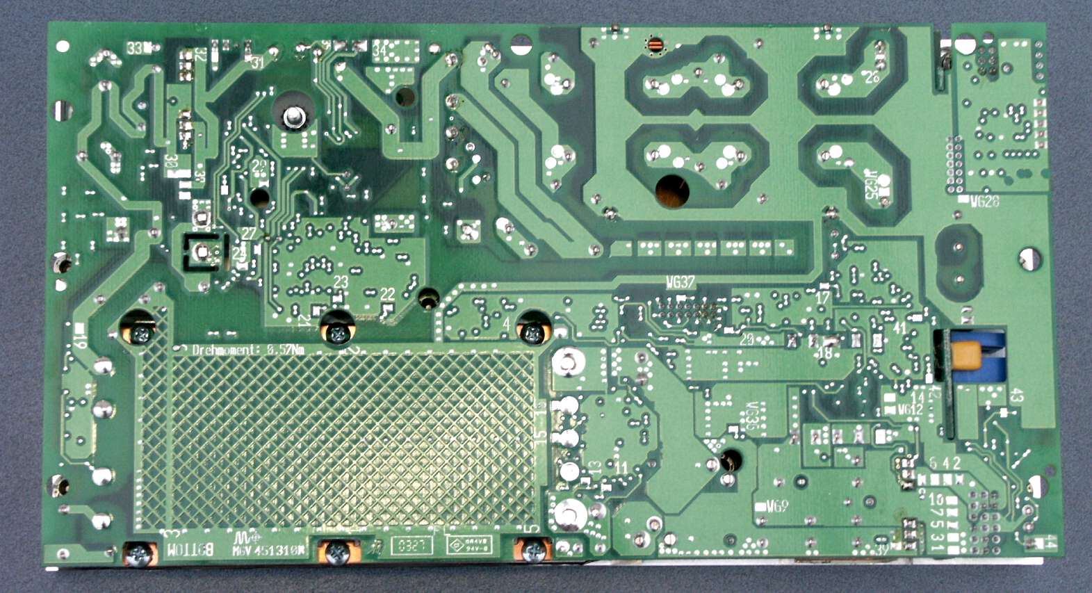
06.05.04 S:\Allgemein\Projects\E_Projects_Documents\800453 Node C 8xx\Doccumentation for FCC_IC type acceptance\Photos\Overview_pictures .doc Page 1 of 2 Photo Overview Photo RF sub component System implementation Photo. No. description description ID No. Node C 843 Node C 837 Interface Unit Photo 0.jpg Top side Final Amplifier DL 158789 x Photo 1.jpg Bottom side Final Amplifier DL 158789 x Photo 2.jpg Top side Final Amplifier DL 161235 x Photo 3.jpg Bottom side Final Amplifier DL 161235 x Photo 4.jpg Top side Final Amplifier UL 160417 x x Photo 5.jpg Bottom side Final Amplifier UL 160417 x x Photo 6.jpg RF-board Top side Digital Channel Module UL 160547 x x Photo 7.jpg RF-board Bottom side Digital Channel Module UL 160547 x x Photo 8.jpg Logic-board Top side Digital Channel Module UL 160547 x x Photo 9.jpg Logic-board Bottom side Digital Channel Module UL 160547 x x Photo 10.jpg RF-board Top side Digital Channel Module DL 160548 x x Photo 11.jpg RF-board Bottom side Digital Channel Module DL 160548 x x Photo 12.jpg Logic-board Top side Digital Channel Module DL 160548 x x Photo 13.jpg Logic-board Bottom side Digital Channel Module DL 160548 x x Photo 14.jpg Top side Bracket Platine 159740 x x Photo 15.jpg Bottom side Bracket Platine 159740 x x Photo 16.jpg Top side Memory Board 159810/159809 x x x Photo 17.jpg Bottom side Memory Board 159810/159809 x x x 06.05.04 S:\Allgemein\Projects\E_Projects_Documents\800453 Node C 8xx\Doccumentation for FCC_IC type acceptance\Photos\Overview_pictures .doc Page 2 of 2 Photo RF sub component System implementation Photo. No. description description ID No. Node C 843 Node C 837 Interface Unit Photo 18.jpg Top side Charge Control Board 160098 x Photo 19.jpg Bottom side Charge Control Board 160098 x Photo 20.jpg Top side Distribution & Alarm Board 160415 x Photo 21.jpg Bottom side Distribution & Alarm Board 160415 x Photo 22.jpg Top side Power Supply 230/115Vac 159514/159126 x
Parts List/Tune Up Info
ID No: 161692 PRELIMINARY Page 1 User’s Manual for Node C Prototype Network Elements with Interface Unit User’s Manual for Node C Network Elements Page 2 M0121A1A_uc.doc © Copyright 2004 Mikom GmbH All rights reserved. All information contained in this manual has been revised thoroughly. Yet Mikom An Andrew Company accepts no liability for any omissions or faults. Mikom An Andrew Company reserves the right to change all hard- and software characteristics without notice. Names of products mentioned herein are used for identification purposes only and may be trademarks and/or registered trademarks of their respective companies. No parts of this publication may be reproduced, stored in a retrieval system, transmitted in any form or by any means, electronical, mechanical photocopying, recording or otherwise, without prior written permission of the publisher. Mikom GmbH An Andrew Company, 16-February-2004 ID No: 161692 PRELIMINARY Page 3 TABLE OF CONTENTS 1 GENERAL 7 1.1 ABBREVIATIONS 7 1.2 HEALTH AND SAFETY WARNINGS 8 1.3 PREAMBLE 9 1.4 INTERNATIONAL CONTACT ADDRESSES 10 2 INTRODUCTION 11 2.1 PURPOSE 11 2.2 THE NODE C NETWORK ELEMENT 11 2.3 QUICK START CHECKLIST 12 3 INSTALLATION 13 3.1 MECHANICAL INSTALLATION 13 3.1.1 General 13 3.1.2 Wall Mounting Procedure 14 3.1.3 Connection Option 16 3.1.4 Pole Mounting Procedures 17 3.2 ELECTRICAL INSTALLATION 20 3.2.1 General 20 3.2.2 Grounding 21 3.2.3 Power Connection 22 3.2.4 Connection of the Antenna Cables 23 3.2.5 Connection of Cable Bridge 23 3.2.6 Connections for Optional Equipment 24 4 COMMISSIONING 25 4.1 GENERAL 25 4.2 SOFTWARE SETUP 26 4.2.1 Remote Control 26 4.2.2 Connection Devices 26 4.2.3 Connection Procedures 26 4.2.3.1 Setup Overview 26 4.2.3.2 Installing the USB driver 27 4.2.3.3 Direct connection for Windows XP 28 4.2.3.4 Modem connection for Windows XP 38 4.2.3.5 Direct connection for Windows 2000 48 4.2.3.6 Accessing the web page 60 4.2.4 Main Menus of the Web Page 61 4.2.4.1 Setup Wizard 61 4.2.4.2 Connectivity and Upload 63 4.2.4.3 Technician Setup 64 4.2.4.4 Alarm Management 65 4.3 TROUBLESHOOTING 66 User’s Manual for Node C Network Elements Page 4 M0121A1A_uc.doc 5 FUNCTIONAL DESCRIPTION 69 5.1 GENERAL 69 5.2 FEATURES OF THE NODE C 72 5.2.1 Filters 72 5.2.2 Digital ICE (Digital Interference Cancellation Equipment) 72 5.2.3 VSWR (Voltage Standing Wave Ratio) 73 5.2.4 RSSI (Receive Signal Strength Indication) 73 5.2.5 Alarmforwarding 73 5.2.6 External Alarms 74 5.2.7 Summary Alarm 75 5.3 COMPONENTS OF THE NODE C AND INTERFACE UNIT 76 5.3.1 Duplexer 76 5.3.2 RF and DC Distribution Unit 78 5.3.3 Digital Channel Module (DCM) 79 5.3.4 Uplink Final Amplifier 80 5.3.5 Downlink Final Amplifier 80 5.3.6 Distribution & Alarm Board 82 5.3.7 Power Supply 83 5.4 OPTIONAL EQUIPMENT 83 5.4.1 Modem with Battery Backup 83 5.4.1.1 Initstrings 84 5.4.1.2 Wireless Modem 84 5.4.1.3 Battery Backup 85 5.4.2 PSU Redundancy 86 5.4.3 High Rejection Filter 86 6 MAINTENANCE 87 6.1 GENERAL 87 6.2 REPLACEMENT OF COMPONENTS 87 6.2.1 Power Supply 88 6.2.2 Battery Backup 89 6.2.3 Fan Unit 89 6.2.4 Modem 90 7 APPENDIX 91 7.1 ILLUSTRATIONS 91 7.1.1 Cabinet Drawings 91 7.1.2 Layout 93 7.2 SPECIFICATIONS 96 7.2.1 Electrical Specifications 96 7.2.2 Mechanical Specifications 98 7.2.3 Specifications for Optional Equipment 98 7.3 PARTSLISTS 99 7.3.1 Interface Unit 99 7.3.2 Node C 100 8 INDEX 101 ID No: 161692 PRELIMINARY Page 5 FIGURES AND TABLES figure 3-1 Positions of drilling holes........................................................................................14 figure 3-2 Wall mounting procedure .......................................................................................15 figure 3-3 Connection option ..................................................................................................16 figure 3-4 Cabinet combining kit.............................................................................................16 figure 3-5 Pole mounted systems...........................................................................................17 figure 3-6 Back-to-back pole mounting...................................................................................18 figure 3-7 Pole mounting two systems ...................................................................................19 figure 3-8 Grounding bolts......................................................................................................21 figure 3-9 Grounding a system ...............................................................................................21 figure 3-10 Power supply plug................................................................................................22 figure 3-11 Mains connector...................................................................................................22 figure 3-12 Front view of antenna connections ......................................................................23 figure 3-13 Connector panel of the Node C............................................................................24 figure 3-14 Connector panel of the Interface Unit ..................................................................24 figure 4-1 Front and top cover screws ....................................................................................25 figure 4-2 Position of mains power switch ..............................................................................25 figure 4-3 USB and null modem cable connection .................................................................27 figure 4-4 Home page of web interface ..................................................................................60 figure 4-5 Setup Wizard..........................................................................................................61 figure 4-6 Connectivity and Upload menu ..............................................................................63 figure 4-7 Technician Setup menu .........................................…
Text truncated - open the document above for the full version.
Test Report
Nemko Test Report: 3L0495RUS1REV1 Applicant: Andrew Corporation Equipment Under Test: Node C 843 (E.U.T.) In Accordance With: FCC Part 22, Subpart H Cellular Band Repeaters Tested By: Nemko Dallas Inc. 802 N. Kealy Lewisville, TX 75057-3136 Authorized By: Tom Tidwell, RF Group Manager Date: 5/20/04 Total Number of Pages: 48 Nemko USA FCC PART 22, SUBPART H CELLULAR BAND REPEATERS EQUIPMENT: Node C 843 PROJECT NO.: 3L0495 Page 2 of 48 Table of Contents SECTION 1. SUMMARY OF TEST RESULTS..............................................................................................................3 SECTION 2. GENERAL EQUIPMENT SPECIFICATION............................................................................................5 SECTION 3. RF POWER OUTPUT..................................................................................................................................7 SECTION 4. OCCUPIED BANDWIDTH.........................................................................................................................8 SECTION 5. SPURIOUS EMISSIONS AT ANTENNA TERMINALS.....................................................................22 SECTION 6. FIELD STRENGTH OF SPURIOUS........................................................................................................28 SECTION 7. FREQUENCY STABILITY........................................................................................................................31 SECTION 8. TEST EQUIPMENT LIST..........................................................................................................................32 ANNEX A - TEST DETAILS..................................................................................................................................................33 ANNEX B - TEST DIAGRAMS.............................................................................................................................................42 Nemko USA FCC PART 22, SUBPART H CELLULAR BAND REPEATERS EQUIPMENT: Node C 843 PROJECT NO.: 3L0495 Page 3 of 48 Section 1. Summary of Test Results Manufacturer: Andrew Corporation Model No.: Node C 843 Serial No.: 14 General: All measurements are traceable to national standards. These tests were conducted on a sample of the equipment for the purpose of demonstrating compliance with FCC Part 22, Subpart H. New Submission Production Unit Class II Permissive Change Pre-Production Unit THIS TEST REPORT RELATES ONLY TO THE ITEM(S) TESTED. THE FOLLOWING DEVIATIONS FROM, ADDITIONS TO, OR EXCLUSIONS FROM THE TEST SPECIFICATIONS HAVE BEEN MADE. See “ Summary of Test Data”. Nemko USA Inc. authorizes the above named company to reproduce this report provided it is reproduced in its entirety and for use by the company’s employees only. Any use which a third party makes of this report, or any reliance on or decisions to be made based on it, are the responsibility of such third parties. Nemko Dallas Inc. accepts no responsibility for damages, if any, suffered by any third party as a result of decisions made or actions based on this report. This report applies only to the items tested. Nemko USA FCC PART 22, SUBPART H CELLULAR BAND REPEATERS EQUIPMENT: Node C 843 PROJECT NO.: 3L0495 Page 4 of 48 Summary Of Test Data NAME OF TEST PARA. NO. SPEC. MEAS. RESULT RF Power Output 22.913(a) 500W 20W Complies Occupied Bandwidth 22.917(c) Input/Output Complies Complies Spurious Emissions at Antenna Terminals 22.917 -13 dBm Complies Complies Field Strength of Spurious Emissions 22.917 -13 dBm E.I.R.P. Complies Complies Frequency Stability 22.355 1.5 ppm N/A Footnotes: Measurement uncertainty for each test configuration is expressed to 95% probability. . Nemko USA FCC PART 22, SUBPART H CELLULAR BAND REPEATERS EQUIPMENT: Node C 843 PROJECT NO.: 3L0495 Page 5 of 48 Section 2. General Equipment Specification Supply Voltage Input: 115V AC Frequency Range: Downlink: 869 – 894 MHz Device operates on Ch 37 to 630 ( 871.11 to 888.90MHz) Frequency Range: Uplink: 824-849MHz Device operates on Ch 37 to 630 (826.11 to 843.90MHz) CDMA GSM NADC CDPD AMPS (F9W) (GXW) (DXW) (F9W) (F8W, F1D) Type of Modulation and Designator: Output Impedance: 50 ohms RF Output (Rated): Downlink: 43 dBm (1 Carrier) (Per Carrier) Uplink: 23 dBm Frequency Translation: F1-F1 F1-F2 N/A Software Duplexer Change Fullband Coverage Band Selection: Nemko USA FCC PART 22, SUBPART H CELLULAR BAND REPEATERS EQUIPMENT: Node C 843 PROJECT NO.: 3L0495 Page 6 of 48 System Diagram Nemko USA FCC PART 22, SUBPART H CELLULAR BAND REPEATERS EQUIPMENT: Node C 843 PROJECT NO.: 3L0495 Page 7 of 48 Section 3. RF Power Output NAME OF TEST: RF Power Output PARA. NO.: 2.1046 TESTED BY: Dustin Oaks DATE: 2/26/2004 Test Results: Complies. Test Data: Modulation Type Power Output (dBm) Uplink CDMA 23.08dBm Downlink CDMA 43.05dBm Equipment Used: 1036, 1626, 1627, 1064, 1469, 1053 Measurement Uncertainty: +/- 1.6 dB Temperature: 21 ?C Relative Humidity: 51 % Nemko USA FCC PART 22, SUBPART H CELLULAR BAND REPEATERS EQUIPMENT: Node C 843 PROJECT NO.: 3L0495 Page 8 of 48 Section 4. Occupied Bandwidth NAME OF TEST: Occupied Bandwidth PARA. NO.: 2.1049 TESTED BY: Dustin Oaks DATE: 2/26/2004 Test Results: Complies. Test Data: See attached plots Equipment Used: 1036, 1626, 1627, 1064, 1469, 1053 Measurement Uncertainty: +/- 1.6 dB Temperature: 21 ?C Relative Humidity: 51 % Nemko USA FCC PART 22, SUBPART H CELLULAR BAND REPEATERS EQUIPMENT: Node C 843 PROJECT NO.: 3L0495 Page 9 of 48 Occupied Band Width / Input Output Plots Downlink CDMA Input Nemko USA FCC PART 22, SUBPART H CELLULAR BAND REPEATERS EQUIPMENT: Node C 843 PROJECT NO.: 3L0495 Page 10 of 48 Downlink CDMA Output Nemko USA FCC PART 22, SUBPART H CELLULAR BAND REPEATERS EQUIPMENT: Node C 843 PROJECT NO.: 3L0495 Page 11 of 48 Uplink CDMA Input Nemko USA FCC PART 22, SUBPART H CELLULAR BAND REPEATERS EQUIPMENT: Node C 843 PROJECT NO.: 3L0495 Page 12 of 48 Uplink CDMA Output Nemko USA FCC PART 22, SUBPART H C…
Text truncated - open the document above for the full version.
Contact Information
Applicant
Michael Shumate(Director, North American Operations)
Technical Contact
Non-Technical Contact
NemkoDustin Oaks
[email protected]972-436-9600
Test Firm
Nemko USA, Inc.Tom Tidwell
Technical Specifications
| # | Rule Parts | Frequency Range | Power Output | Emission | Tolerance |
|---|---|---|---|---|---|
| 2 | 22H | 824 MHz - 849 MHz | 203.00 mW | F9W | Amp |
Other Applications from Andrew Wireless Innovations Group

BCR-IONEUAP
Mar 10, 2015ION-E
Equipment Class
B2I - Part 20 Industrial Booster (CMRS)
BCR-M17P26
Feb 08, 2012ION-M17P/26 EU
Equipment Class
TNB - Licensed Non-Broadcast Station Transmitter
BCR-TFAHUS717
Aug 14, 2011ION-B TFAH-US7/17
Equipment Class
TNB - Licensed Non-Broadcast Station Transmitter
BCR-TFAHUS4B
Jul 20, 2011ION-B TFAH-US4B
Equipment Class
PCB - PCS Licensed Transmitter
BCR-TFBM17
Jan 23, 2011ION-B TFBM17 FIBER OPTIC DISTRIBUTION REMOTE UNIT
Equipment Class
TNB - Licensed Non-Broadcast Station Transmitter