BCR-TFAM1719Optical wireless distribution system
Andrew Wireless Innovations Group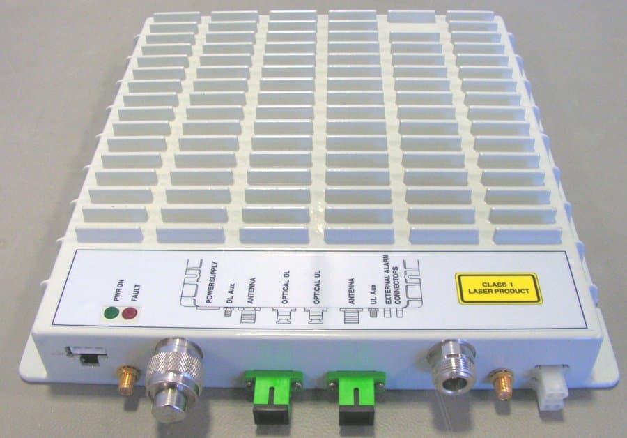
Click to zoom
Application Details
- Equipment Class
- PCB - PCS Licensed Transmitter
- Date of Grant
- Jun 04, 2007
- Application Purpose
- Original Equipment
- Date of Application
- Jun 03, 2007
- Equipment Note
- Optical wireless distribution system
- Frequency Range
- 2110.00000000 - 2155.00000000
- Country
- United States
Documents & Files
Document Text
Text extracted from the exhibit documents filed with the FCC. Open a document above to read the original.
Users Manual
User Manual MN024-08 PLU S 1 MN024-08 © Copyright Andrew Wireless Systems Srl This publication is issued to provide outline information and is not aimed to be part of any offer and contract. The Company has a policy of continuous product development and improvement and we therefore reserve the right to vary information quoted without prior notice. System and Customer care is available world-wide through our network of Experts. The company is certified ISO 9001 and ISO14000. Andrew Wireless Systems Srl Via Pier De Crescenzi 40 48018 Faenza, Italy Tel: +39 0546 697111 Fax: +39 0546 682768 www.andrew.com INDEX 0. Index 2 1. Introducing Britecell Plus 4 1.1 The Features 5 1.2 Brief Description of Britecell Plus 5 1.3 Britecell Plus features 6 1.4 Britecell Plus typical applications 7 2. Equipment Overview 9 2.1 The Britecell Plus Remote Unit and its relevant accessories 10 2.2 the Britecell Plus Master Unit 12 2.2.1 The Fast Master Unit 12 2.2.2 The Rack-based Master Unit 12 2.3 Block diagrams 16 3. TFAx Remote Unit 22 3.1 Introduction 23 3.2 Case A remote unit 25 3.3 Case B remote unit 45 3.4 Case L remote unit 63 3.5 Case F remote unit 79 3.6 Wi-Fi Booster TFBW 90 4. Fast Master Unit 100 5. Rack based master unit 113 5.1 19” Subrack TPRNx4 114 5.2 Master Optical TRX, TFLN 126 5.3 Two-way splitter/combiner TLCN2 138 5.4 Four-way splitter/combiner TLCN4 142 5.5 RF dual band coupler TLDN 146 5.6 RF tri-band coupler TLTN 150 5.7 RF Duplexer TDPX 154 5.8 Base Station Interface TBSI 158 5.9 Power Limiter TMPx-10 162 5.10 Wi-Fi Local Interface 168 5.11 The interconnect link (i-link) 172 5.11.1 Introduction 173 5.11.2 TILx-HL Interconnect link 177 5.11.3 TILx-HLW Interconnect link 195 5.12 Remote Supply Unit TRS/TRSN 216 6. Warning and Safety Requirements 222 6.1 Environmental conditions 223 6.2 Installation site Features 223 6.3 Safety and Precautions during Installation or maintenance 224 6.4 Power Supply Connection 225 2 User Manual 6.5 Safety and Precautions for Lasers 226 6.6 Health and Safety Warnings 226 6.7 Electromagnetic Fields and RF Power 227 6.7 Warning Labels 230 7. Technical support 231 7.1 Returning Equipment 231 Appendix A: System Commissioning 233 Appendix B: EU Guidelines for WEEE disposal 237 3 MN024-08 4 User Manual 1. Introducing Britecell Plus 5 MN024-08 1.1 The Features Britecell Plus is an innovative platform designed in order to provide an effective and flexible coverage to a large variety of indoor scenarios. Thanks to its high modularity, its low power consumption, and its full- transparency to protocols and modulation formats, Britecell Plus is the perfect plug&play solution to distribute any wireless standard (including GSM, GPRS, EDGE, CDMA, WCDMA, and WLAN IEEE 802.11b) to the in-building environments requiring reliable and interference-free communications, as well as high traffic capacity and maximum flexibility about future expansions. These unique features make the Britecell Plus platform suitable also for applications to critical areas experiencing difficulties in establishing and keeping phone calls, while its compact design always guarantees a minimum aesthetic impact. 1.2 Brief Description of Britecell Plus Britecell Plus is a Distributed Antenna System (DAS) based on the Radio-over- Fibre (RoF) technology, and capable of carrying wireless mobile signals through the 800MHz - 2500MHz frequency range regardless of their protocol and their modulation format. The system has two basic components, a Master Unit and a Remote Unit. The Master Unit is made of one or more subracks typically connected to the BTS (Base Tranceiver Station) through either a repeater (RF interface) or a coaxial cable. Each Remote Unit is connected with a dedicated pair of single-mode optical fibres (one for UL and one for DL) to the Master Unit. These optical fibres work on 1310 nm wavelenght and provide low losses and almost unlimited bandwidth, available for future system developments. Britecell Plus is a modular system whose basic components are: • one Master Unit made of one or more subracks, each providing 12 module slots. Each slot can host either an active or a RF passive device (chosen among the wide range of Britecell Plus options), in order to meet the planned design requirements; • a variable number of Remote Units (TFAx), whose function is feeding the antenna passive network; • a proper number of indoor antennas, suitable to provide radio coverage to the area. Britecell Plus is fully compatible with any type of indoor antennas; • the optical cables required to connect the 19” subracks to the TFAx. 6 User Manual Fig. 1.1: Britecell Plus system block diagram. 1.3 Britecell Plus Features The following lines report a brief summary of Britecell Plus main features: • multiband 2G, 2.5G and 3G – 802.11b WLAN compatible: Britecell Plus is completely transparent to any transmission protocol and modulation format, and it can distribute any 2G, 2.5G, 3G wireless standard. In addition, it allows to carry also the WLAN (802.11b/g) service over the same infrastructure; • modular configuration for flexible design: by properly setting some parameters like the amount of RUs and the antenna locations, the Britecell Plus architecture can follow the environment specific features in order to obtain the most effective radio-coverage of the indoor area. The modularity of the system allows easy modifications for future growth and increasing traffic; • easy to install: the intelligent plug & play Britecell Plus system includes an Automatic Gain Control (AGC), that eliminates system gain variations regardless of optical loss. This avoids the need for field adjustments, thus reducing design, installation and optimization time. • low-power consumption: establishing a “quasi line-of-sight propagation” towards all mobile phones inside the area, Britecell Plus works with low power levels. Low power levels have two great advantages: 1) allow mobile phones to work at lower power levels, thus limiting the radiat…
Text truncated - open the document above for the full version.
Users Manual
113 MN024-08 5. Rack-based Master Unit 114 User Manual 5.1. TPRNx4 subrack TPRN 115 MN024-08 Major TPRN features The TPRNx4 is a 19”subrack where all the Britecell Plus plug-in modules can be inserted. Britecell Plus equipment provides a wide variety of these sub-rack models differentiated by power supply. Each one is provided with: • 12 free slots, each with Height=4HE, Width=7TE • Power supply 220 Vac or -48 Vdc • Locally or remotely connectable through: ¾ RS232 serial port ¾ RS485 two-wire bus ¾ sub-D 15 pin male-connector • Internal microcontroller for I2CBUS alarm collection • Manual reset button, able to re-initialize both the inserted modules and the TPRN microcontroller • Manual stand-by button, able to re-initialize the inserted modules, while keeping the TPRN microcontroller working. TPRN Power supply (picture shows 220Vac version) RS232 port RS485 ports sub D 15 connector buttons Fig. 5.1: Front view of the TPRN sub-rack with power supply and communication ports on the back Fig. 5.2: Back view of the TPRN sub- rack with power supply and communication ports on the back Module name: Subrack TPRNx4 116 User Manual TPRN models A brief description of all the available TPRN sub-racks is reported hereinafter. Passive sub-rack (TPRN04) • TPRN04 is a passive sub-rack. It does not provide power supply to any inserted module, and therefore it is designed to host passive modules only. It can be useful in a multi-sub-rack system, in case the customer decides to put all the active modules in an active sub-rack, to be chosen among the following ones. 220 Vac powered sub-racks (TPRN14 / TPRN24) • TPRN14 is an active sub-rack designed to be fed through 220 Vac universal mains. Both the connector for 220Vac power supply and the communication ports are placed on the sub-rack rear. The 220 Vac power supply is not redundant (ie, no spare adapter is provided). • TPRN24 is an active sub-rack designed to be fed through 220 Vac universal mains. Both the connector for 220Vac power and the communication ports are placed on the sub-rack rear, and the 220 Vac power supply is redundant: i.e., a spare adapter guarantees the correct system operations even in case the main 220Vac adapter has a breakdown. -48Vdc powered sub-rack (TPRN34) • TPRN34 is an active sub-rack designed to be fed through –48 Vdc negative supply. Both the connector for -48Vdc power supply and the communication ports are placed on the sub-rack rear. TPRN power supply All the TPRN models refer to one of the following power supplies. Universal mains (85 to 264Vac, 50/60Hz). This connector is mounted on the TPRN back panel either for the redundant version or the simple one. A ground terminal and a couple of fuses are also included. Fuses have to be replaced in case they fail (when it happens the supervision system detects the failure). TPRN Fuses Fig. 5.3: 85 to 264Vac connector 11 7 MN024-08 -48 Vdc (-72 to -36 Vdc) This connector is mounted on TPRN back panel. A fuse is provided underneath the –48 Vdc connector, and has to be replaced in case it fails (when it happens the supervision system detects the failure). Whatever power supply is chosen (85 to 264 Vac or -72 to - 36 Vdc) an additional external ground terminal is provided on the TPRN rear (fig. 5.5). The external power supply (220Vac or -48Vdc) is converted into a +12Vdc voltage allowing feeding the active modules inserted into the TPRN. TPRN ports The TPRN sub-rack is provided with a set of I/0 ports which allows the connection to any external device. RS232 serial port The RS232 serial port can be used to connect the TPRN sub-rack to the remote supervision unit or to a laptop running LMT software. Please note that a standard RS232 cable is needed. The connection baud rate can be set to 9600bps or 19200bps, by properly setting the dip-switch 5 standing on the interior TPRN backplane (fig. 5.6). The baud rate setting through dip-switch 5 is shown in table 5.1. TPRN Fig. 5.4: -72÷-36Vdc connector Fig. 5.5: ground terminal on the rear RS485-addressing dip-switches (1-4) Baud-rate dip-switch (5) Fig. 5.6: Dip-switches on TPRN backplane. Fuse black terminal: 0V blue terminal:-72 to -36Vdc 118 User Manual Whichever baud rate you choose through dip-switch 5, remember that: • the same RS232 connection speed must be set up on the remote supervision unit • the baud rate which is selected through the dip-switch 5 sets the connection speed for both the RS232 port and the RS485 port as the TPRN uses both ports with the same rate. RS485 port The RS485 port consists of two RJ45 connectors, which can both work as input or output ports towards a RS485 bus. This RS485 bus has to be used in order to connect a multi sub-rack system to the remote supervision unit. In this case: • the TPRN sub-racks have to be connected one another via RS485 bus in a daisy chain; • In order to monitor the whole system, the remote supervision unit has to be connected to one of the TPRN sub-racks through RS232 port. Before connecting the TPRN sub-racks belonging to a multi-sub-rack system, remember to assign an exclusive binary address to each one. This is essential in order to let the supervision system recognize the different master units without any conflict. The binary address assignment can be done through dip-switches 1,2,3,4, which stand on interior TPRN backplane (see figure 5.6). A list of the correspondences between the addresses and the dip-switches is provided by table 5.2: simply note that dip-switch 1 is the least significant binary digit, while dip-switch 4 is the most significant one. Address Dip-switch 1 Dip-switch 2 Dip-switch 3 Dip-switch 4 0001 ON OFF OFF OFF 0010 OFF ON OFF OFF 0011 ON ON OFF OFF 0100 OFF OFF ON OFF 0101 ON OFF ON OFF 0110 OFF ON ON OFF 0111 ON ON ON OFF 1000 OFF OFF OFF ON 1001 ON OFF OFF ON 1010 OFF ON OFF ON 1011 ON ON OFF ON 1100 OFF OFF ON ON 1101 ON OFF ON ON 1110 OFF ON ON ON TPRN Baud rate [bps] Dip-switch 5 9600 OFF 19200 ON Table 5.1: Setting RS232 baud rate throu gh dip-switc…
Text truncated - open the document above for the full version.
Cover Letter(s)
Andrew Corporation 108 Rand Park Drive Garner, NC 27529 Tel: (919) 329-8941 Fax: (919) 329-8950 www.andrew.com 17 October, 2006 American Telecommunications Certification Body, Inc. 6731 Whittier Avenue Suite C110 McLean, VA 22101 To Whom It May Concern: NTS Laboratory is authorized to act on our behalf, until otherwise notified, for applications to American Telecommunications Certification Body, Inc. (ATCB). We certify that we are not subject to denial of federal benefits, that includes FCC benefits, pursuant to Section 5301 of the Anti-Drug Abuse Act of 1988, U.S.C. 862. Further, no party, as defined in 47 CFR 1.2002 (b) to the application is subject to denial of federal benefits, that includes FCC benefits. Thank you. Regards, Michael Williamson Product Manager Andrew Corporation
Cover Letter(s)
Andrew Corporation 108 Rand Park Drive Garner, NC U.S.A. 27529 Tel: (919) 771-2570 Fax: (919) 771-2360 www.andrew.com 14 February 2007 Equipment Autorisation Division Federal Communications Commission 7435 Oakland Mills Road Columbia, MD 21046 FCC ID: BCR-TFAM1719 Product Name: ION-B Request for Confidentiality Pursuant to Sections 0.457 and 0.459 of the commission’s rules, we hereby request that the following documents be held confidential: • Schematics • Manual • Datasheet • Block Diagram These materials contain trade secrets and proprietary information and are not customarily released to the public. The public disclosure of this information might be harmful to the company and provide unjustified benefits to our competitors. The manual is only provided for use by trained technicians and is not available to the general user from Andrew’s website. Dated this 14 Day of February 20 07 By: Michael Williamson Signature Printed Title: Product Manager On behalf of : Andrew Corporation Telephone: (919) 329 8941
Cover Letter(s)
Part 22 22.99 “In-building radiation systems. Supplementary systems comprising low power transmitters, receivers, indoor antennas and/or leaky coaxial cable radiators, designed to improve service reliability inside buildings or structures located within the service areas of stations in the Public Mobile Services.” Part 24 No special definitions given – use Part 22 concepts. FIBER-OPTIC AND OTHER SIMILAR RF DISTRIBUTION SYSTEMS Fiber-optic distribution systems are a type of in-building radiation system that receives RF signals from an antenna, distributes the signal over fiber-optic cable, and then retransmits at another location for example within a building or tunnel. Most fiber-optic systems are signal boosters; however, some may be repeaters. These systems generally have two enclosures typically called host (or local or donor unit) and remote. Some systems may also have an optional expander box for fan-out to multiple remotes. The system transmits downlink signals from the remote unit to handsets, portables, or clients, and transmits uplink signals via from the host unit. Usually but not always the uplink goes through an intermediate amplifier to a “donor” antenna. Therefore both uplink and downlink must be tested, unless filing effectively documents how connection of uplink to donor antenna with or without an intermediate amplifier will be prevented, such as for always only a cabled connection to a base station(see note 1 below). Fiber-optic systems are not amplifiers (AMP equipment class) – they are equipment class TNB or PCB. The same approval procedures also apply for multiple-enclosure systems connected by coax cable. Synonyms and related terms: in-building radiation system, coverage enhancer, distributed antenna system, fiber-optic distribution system, converter, donor antenna NOTE 1: The ION-B is identified in the User’s Manual (page 4, para. 1) as a “distributed antenna system”. Because of its function and the fact that it does not perform channel translation, it would be classified as a signal booster according to the definition in 22.99. Within the User Manual it is stated that the master unit is connected to the base station via coaxial cable. Typical in-building or distributed antenna systems can consist of five different components (enclosures), not counting antennas: 1) host unit a) transmits uplink to base station via antenna thru coax, passive interface unit , or active interface unit (amplifier) b) sends base-station downlink via fiber-optic or coax to remote c) receives handset uplink via fiber-optic or coax from remote d) optional connection to expansion unit via fiber-optic e) separate FCC ID from remote, unless electrically identical f) non-transmitting host unit(see note 2 below) i) connects directly to a base station via coax cable but does not connect to antenna or amplifier ii) Part 15 digital device subject to Verification, no FCC ID 2) remote unit a) receives base-station downlink via fiber-optic or coax from host, transmits via antenna to handsets b) returns handset uplink via fiber-optic or coax to host c) separate FCC ID from remote, unless electrically identical(see note 2 below) 3) expansion unit a) fiber-optic or coax from host b) fiber-optic or coax fan-out to remote(s) c) Part 15 digital device subject to Verification, no FCC ID 4) passive interface unit a) contains attenuators, splitters, combiners b) coax cable connection between host and base-station c) passive device, no FCC ID 5) active interface unit a) amplifies uplink signal from host unit for transmit by donor antenna b) attenuates downlink from donor antenna c) coax cable connection between host and active interface unit d) usually has separate FCC ID; in some cases could be combined/included with host as one enclosure NOTE 2: The ION-M19P system consists of the master unit and remote unit(s). The master and remote are in separate enclosures and are connected via fiber optic cable. Since the master or host unit always connects directly to a BTS via coaxial cable and not to an antenna or amplifier, it is a non-transmitting host according to the FCC guidance above and thus is subject to Part 15 digital device Verification and does not require an FCC ID. REMINDER SHEET ITEMS Form 731 entries – a) For ERFPA as defined above i) In one enclosure (1) Equipment Class – AMP (2) List AMP in frequency tolerance field of Form 731 (3) List emission designators without necessary bandwidth (e.g., F3E, F1D) ii) In two enclosures (1) Does not exist (if it does, use same entries as for one enclosure) b) For Booster as defined above i) In one enclosure (1) Equipment Class – TNB or PCB (2) List AMP in frequency tolerance field of Form 731 (3) List emission designators without necessary bandwidth (e.g., F3E, F1D) (4) List in comments field the word “booster” ii) In two enclosures (host/remote) (1) Two separate FCC IDs/applications(Not applicable...see Note 2) (2) Equipment Class – TNB or PCB (3) List AMP in frequency tolerance field of Form 731 (4) List emission designators without necessary bandwidth (e.g., F3E, F1D) (5) List in comments field the words “Part of booster system used with FCC ID: xxxyyy.” (Where xxxyyy is FCC ID of other TNB or PCB in system).(I believe i(4) above would be the appropriate statement for this device. See Note 2.) c) For Repeater as defined above i) In one enclosure (1) Equipment Class – TNB or PCB (2) List AMP in frequency tolerance field of Form 731 if device contains no frequency translation; otherwise, measure frequency tolerance and list. (3) List in comments field the word “repeater” ii) In two enclosures (host/remote) (1) Two separate FCC IDs/applications (2) Equipment Class – TNB or PCB (3) List AMP in frequency tolerance field of Form 731 if device contains no frequency translation; otherwise, measure frequency tolerance and list. (4) List in comments field the words “Part of repeater system used with FCC ID: xxxyyy.” (Where xxxyyy is FCC ID of other TNB or PCB in system).…
Text truncated - open the document above for the full version.
Cover Letter(s)
(a) Frequency range in MHz (b) Rated RF power output in watts (c) Frequency tolerance %, Hz, ppm (d) Emission designator (See 47 CFR §2.201 and § 2.202) Technology 1930 - 1990 1930 - 1990 1930 – 1990 1930 - 1990 1930 - 1990 2110 – 2155 2110 – 2155 .0631 (18 dBm) .0316 (15 dBm) .1260 (21 dBm) .0790 (19 dBm) .1000 (20 dBm) .0794 (CDMA1700) .0398 (W-CDMA1700) AMP AMP AMP AMP AMP AMP AMP F9W F9W GXW GXW DXW F9W F9W CDMA1900 W-CDMA1900 GSM1900 EDGE1900 TDMA1900 CDMA1700 W-CDMA1700
Cover Letter(s)
American Telecommunications Certification Body Inc. 6731 Whittier Ave, McLean, VA 22101 May 16, 2007 RE: FCC ID: BCR-TFAM1719_ATCB004892 Attention: Tom Tidwell I have a few comments on this Application. Please note that further comments may arise in response to answers provided to the questions below. 1. Please note that the internal photos appear to have shielding still on the board. Please remove any shielding and provide photos of the circuitry underneath. Alternately, please explain why the metal shown on the board is not shielding and why it should not be removed to show the circuitry underlying. 2. Please provide the MPE calculation results for the 2100MHz part 27 band. 3. Please note that the manual states that 802.11 transmissions can also be amplified. Please note that if this is referring to part 15 802.11, no such testing for these signals has been provided. Please also note that such transmissions of this type via an amplifier of this nature may not be allowed under part 15.247. If this is referring to part 27 frequencies, please explain the context and statement concerning 802.11 signals in the manual. 4. Please note that the manual mentions narrowband PCS use however, there does not appear to be testing to that rule section. Please explain and please provide all necessary testing for all modulation types and rule parts. 5. Please note that the manual mentions use of the device in the part 90 rule sections. If this device is intended to be used in this band please provide the necessary testing. If this device is not intended for use in the part 90 rule sections, please explain the reference in the manual. 6. Please note that the manual indicates use in the 850MHz cell bands but no test data has been provided to support this band. Please explain and please provide test data for all rule parts used by the device. 7. Please note that the report states Edge technology emissions designator as GXW. Please note that the typical emissions designator used for EDGE technology is G7W. Please explain the use of GXW for EDGE in the report. 8. Please note that the test data table on page 12 of the report shows the first column as “Channel”, however, the listings appear to be the frequency. Please clarify. 9. Please note that as this is a part 27 AWS system also, it will have to go through the permit but ask route. This also means that the part 24 section will not be able to be granted until the part 27 has been approved for grant by the FCC. 10. Please note that the upper signal on the graph on page 74 of the report appears to be over the red mask line. It is not possible to determine if this is an error in the line or if the device is actually failing the band edge. Please clearly identify the upper band limit so compliance can be easily be determined. 11. Please note that in regards to item 10 there are a number of plots where the signal exceeds the red limit line. Some of these plots may be showing an improper limit line. Please consider remarking the limit lines (red lines) to show actual limit frequencies etc. Dennis Ward mailto:[email protected] The items indicated above must be submitted before processing can continue on the above referenced application. Failure to provide the requested information may result in application termination. Correspondence should be considered part of the permanent submission and may be viewed from the Internet after a Grant of Equipment Authorization is issued. z Page 2 May 16, 2007 Please do not respond to this correspondence using the email reply button. In order for your response to be processed expeditiously, you must submit your documents through the AmericanTCB.com website. Also, please note that partial responses increase processing time and should not be submitted. Any questions about the content of this correspondence should be directed to the sender.
Cover Letter(s)
Responses RE: FCC ID: BCR-TFAM1719_ATCB004892 Attention: Tom Tidwell I have a few comments on this Application. Please note that further comments may arise in response to answers provided to the questions below. 1. Please note that the internal photos appear to have shielding still on the board. Please remove any shielding and provide photos of the circuitry underneath. Alternately, please explain why the metal shown on the board is not shielding and why it should not be removed to show the circuitry underlying. Please find additional photos with the shield removed. These are actually metal barriers that compartmentalize sections of the circuit but I found that removing them does give a clearer view of the PWB. 2. Please provide the MPE calculation results for the 2100MHz part 27 band. Please find an additional MPE calculation for 2100 MHz band. 3. Please note that the manual states that 802.11 transmissions can also be amplified. Please note that if this is referring to part 15 802.11, no such testing for these signals has been provided. Please also note that such transmissions of this type via an amplifier of this nature may not be allowed under part 15.247. If this is referring to part 27 frequencies, please explain the context and statement concerning 802.11 signals in the manual. The manual is intended to cover many devices. The unit does include what is referred to as “auxillary” ports. The function of these ports is simply to take an rf signal (at the BTS side), convert the rf to an optical signal and send the signal over fiber to the “remote” device. The remote is actually the device that we are certifying. The “auxillary” portion of the circuit is nothing more than a broadband rf to optical (and optical to rf) link. The signal is not amplified or altered in any way. The “auxillary” ports on the remote would be attached to a separately approved device manufactured by Andrew Corp. This separate device would really be similar to the remote device that we are now certifying but would cover a different frequency band. In some EU countries the auxillary remote extension would be used for a licensed WiFi service (thus the reference in the manual). This function is not usable without the auxillary remote device. Andrew is not attempting at this time to approve such a device. 4. Please note that the manual mentions narrowband PCS use however, there does not appear to be testing to that rule section. Please explain and please provide all necessary testing for all modulation types and rule parts. This is again a reference to a different remote device that would be approved separately. This is a future product and will be certified at a later date. The remote device that we are certifying with this application covers only the PCS and AWS bands. The designation TFAM1719 indicates that this remote only works in the AWS band (generally referred to as 1700 MHz band) and Broadband PCS 1900 MHz band. 5. Please note that the manual mentions use of the device in the part 90 rule sections. If this device is intended to be used in this band please provide the necessary testing. If this device is not intended for use in the part 90 rule sections, please explain the reference in the manual. This is again a reference to a different remote device that would be approved separately. This is a future product and will be certified at a later date. The remote device that we are certifying with this application covers only the PCS and AWS bands. 6. Please note that the manual indicates use in the 850MHz cell bands but no test data has been provided to support this band. Please explain and please provide test data for all rule parts used by the device. This is again a reference to a different remote device that would be approved separately. This is a future product and will be certified at a later date. The remote device that we are certifying with this application covers only the PCS and AWS bands. 7. Please note that the report states Edge technology emissions designator as GXW. Please note that the typical emissions designator used for EDGE technology is G7W. Please explain the use of GXW for EDGE in the report. This was a typo. It should have been G7W. I am uploading a corrected report. 8. Please note that the test data table on page 12 of the report shows the first column as “Channel”, however, the listings appear to be the frequency. Please clarify. Another typo. I decided it might be better to put the actual frequency instead of channel designation but did not change the title in the table. See the corrected report. 9. Please note that as this is a part 27 AWS system also, it will have to go through the permit but ask route. This also means that the part 24 section will not be able to be granted until the part 27 has been approved for grant by the FCC. It looked like from references made in the May TCB conference call with FCC that they are only interested in seeing AWS devices that fall into Portable RF Exposure category. I was not on the call so I defer to your judgment. We are not using any different modulations such as 802.16e, only the normal cellular modulations. 10. Please note that the upper signal on the graph on page 74 of the report appears to be over the red mask line. It is not possible to determine if this is an error in the line or if the device is actually failing the band edge. Please clearly identify the upper band limit so compliance can be easily be determined. The graph on page 74 was done with 1 MHz RBW because the intent was not really to show band edge compliance. Graphs for band edge showing the emissions in the 1 MHz adjacent to the band edges are shown on pages 59 – 73. 11. Please note that in regards to item 10 there are a number of plots where the signal exceeds the red limit line. Some of these plots may be showing a…
Text truncated - open the document above for the full version.
Contact Information
Applicant
Michael Shumate(Director, North American Operations)
Technical Specifications
| # | Rule Parts | Frequency Range | Power Output | Emission | Tolerance |
|---|---|---|---|---|---|
| 7 | 27 | 2.11 GHz - 2.15 GHz | 39.80 mW | F9W | Amp |
Other Applications from Andrew Wireless Innovations Group

BCR-IONEUAP
Mar 10, 2015ION-E
Equipment Class
B2I - Part 20 Industrial Booster (CMRS)
BCR-M17P26
Feb 08, 2012ION-M17P/26 EU
Equipment Class
TNB - Licensed Non-Broadcast Station Transmitter
BCR-TFAHUS717
Aug 14, 2011ION-B TFAH-US7/17
Equipment Class
TNB - Licensed Non-Broadcast Station Transmitter
BCR-TFAHUS4B
Jul 20, 2011ION-B TFAH-US4B
Equipment Class
PCB - PCS Licensed Transmitter
BCR-TFBM17
Jan 23, 2011ION-B TFBM17 FIBER OPTIC DISTRIBUTION REMOTE UNIT
Equipment Class
TNB - Licensed Non-Broadcast Station Transmitter