BEJD2342PYPart15 Subpart B-LCD Monitor
LG Electronics USA, Inc.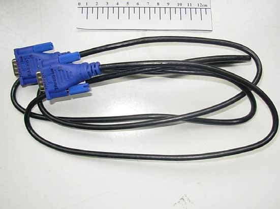
Click to zoom
Application Details
- Equipment Class
- JBP - Part 15 Class B Computing Device Peripheral
- Date of Grant
- Mar 15, 2011
- Application Purpose
- Original Equipment
- Date of Application
- Mar 15, 2011
- Equipment Note
- Part15 Subpart B-LCD Monitor
- Company
- LG Electronics USA, Inc.
- Country
- United States
Documents & Files
Document Text
Text extracted from the exhibit documents filed with the FCC. Open a document above to read the original.
Users Manual
www.lg.com OWNER’S MANUAL SUPER 3D MONITOR D2342P Please read this manual carefully before operating your set and retain it for future reference. SUPER 3D MONITOR MODEL ENGLISH 2 ENG ENGLISH TABLE OF CONTENTS CONTENTS 3 ASSEMBLING AND PREPARING 3 Unpacking 4 Parts and buttons 6 Setting up the Monitor set 6 - Attaching the Stand Base 6 - Detaching the Stand Base and Body 7 - Mounting on a table 8 - Mounting on a wall 10 USING THE MONITOR SET 10 Connecting to a PC 10 - D-SUB connection 10 - DVI-D connection 10 - HDMI connection 12 CUSTOMIZING SETTINGS 12 Accessing The Main Menus 13 Customizing Settings 13 - Menu Settings 14 - 3D Settings(Only 3D mode) 14 - Volume Settings (Only supported in HDMI) 15 - SUPER ENERGY SAVING Settings 16 TROUBLESHOOTING 18 TROUBLESHOOTING WHEN USING 3D MODE 19 SPECIFICATIONS 20 Preset Modes (Resolution) 20 HDMI 3D TIMING 20 Indicator 21 PRECAUTIONS TO TAKE WHEN VIEWING 3D IMAGES 22 PROPER POSTURE 22 Proper posture for using the Monitor set. 22 Precautions to take when viewing 3D im- ages 4 ENG ENGLISH ASSEMBLING AND PREPARING Parts and buttons HDMID-SUB AC-IN/ 䔜㹷彺⅌ DVI-D Power Indicator yy Lighting On: Turned on yy Lighting Off: Turned off Connection panel (See p.10) Button (See p.13) (Power Button) 5 ENG ENGLISH ASSEMBLING AND PREPARING ButtonDescription MENUAccesses the main menus.(See p.13) OSD LOCKED/ UNLOCKED This function allows you to lock the current control settings, so that they cannot be inadvertently changed. Press and hold the MENU button for several seconds. The message "OSD LOCKED" should appear. You can unlock the OSD controls at any time by pushing the MENU button for several seconds. The message "OSD UNLOCKED" should appear. SUPER ENERGY SAVING Button Use this button to enter SUPER ENERGY SAVING menu.For more information.(See p.15) 3D3D display settings.(See p.14) AUTOWhen adjusting your display settings, always press the AUTO button on the MONITOR SETUP OSD. (Only supported in Analog Mode) The best display mode1920 x 1080 VOLUME (Only HDMI mode)Adjust the volume of the Monitor set.(See p.14) INPUT You can choose the input signal. y When two input signals are connected, you can select the input signal (D-SUB/DVI/ HDMI) you want. y When only one signal is connected, it is automatically detected. The default setting is D-SUB. EXITExit the OSD(On Screen Display). (Power Button) Turns the power on or off. Power IndicatorThe power indicator stays blue if the display is running properly (On Mode). If the display is in Sleep Mode, the power indicator blinks blue. 6 ENG ENGLISH ASSEMBLING AND PREPARING Setting up the Monitor set Attaching the Stand Base 1 Place the Monitor set with the screen side down on a flat and cushioned surface. Lay a foam mat or soft protective cloth on the surface to protect the screen from damage. yy This illustration depicts the general model of connection. Your monitor may differ from the items shown in the picture. yy Do not carry the product upside down holding only the stand base. The product may fall and get damaged or injure your foot. CAUTION CAUTION Detaching the Stand Base and Body 1 Place the Monitor set with the screen side down on a flat and cushioned surface. 2 Turn the screw to the left, and then pull out the Stand Base from the Stand Body. 3 Attach the Stand Base and then tighten the screw to the right with a Coin. 2 Assemble the Stand Body into the product in the correct direction as shown in the picture. Make sure you push it until you hear it “click”. 3 Pull out the Stand Body from the Monitor set. Stand Body Stand Base Hinge Body 7 ENG ENGLISH ASSEMBLING AND PREPARING Mounting on a table 1 Lift and tilt the Monitor set into its upright position on a table. Leave a 10 cm (minimum) space from the wall for proper ventilation. 2 Connect the Power Cord to a wall outlet. 3 Press (Power) button on the front switch panel to turn the power on. 10 cm 10 cm 10 cm 10 cm When you adjust the angle, do not hold the bottom of the Monitor set frame as shown on the following illustration, as may injure your fingers. Do not touch or press the screen when adjusting the angle of the monitor. WARNING Unplug the power cord before moving the Monitor to another location. Otherwise electric shock may occur. Tilt from +15 to -5 degrees up or down to adjust the angle of the Monitor set to suit your view. CAUTION NOTE FrontRear 15- 5 8 ENG ENGLISH ASSEMBLING AND PREPARING Mounting on a wall For proper ventilation, allow a clearance of 10 cm on each side and from the wall. Detailed instructions are available from your dealer, see the optional Tilt Wall Mounting Bracket Installation and Setup Guide. When you install the Monitor set using a wall mounting interface (optional parts), attach it carefully so it will not drop. Please use VESA standard as below. yy 784.8 mm (30.9 inch) and under * Wall Mount Pad Thickness : 2.6 mm * Screw : Φ 4.0 mm x Pitch 0.7 mm x Length 10 mm yy 787.4 mm (31.0 inch) and above * Please use VESA standard wall mount pad and screws. 10 cm 10 cm 10 cm 10 cm Using the Kensington security system The Kensington security system connector is located at the back of the Monitor set. For more information of installation and using, refer to the manual supplied with the Kensington security system or visit http://www.kensington.com. Connect the Kensington security system cable between the Monitor set and a table. The Kensington security system is optional. You can obtain it from most electronics stores. NOTE 9 ENG ENGLISH USING THE MONITOR SET yy Disconnect the power cord first, and then move or install the Monitor set. Otherwise electric shock may occur. yy If you install the Monitor set on a ceiling or slanted wall, it may fall and result in severe injury. yy Use only an authorized LG wall mount and contact the local dealer or qualified personnel. yy Do not over tighten the screws as this may cause damage to the Monitor set and void your warranty. yy Use only screws and wall mounts that meet the VESA standard. Any damage…
Text truncated - open the document above for the full version.
Users Manual
Regulatory Information cont. FCC Compliance Statement This equipment has been tested and found to comply within the limits of a Class B digital device pursuant to Part 15 of the FCC Rules. These limits are designed to provide reasonable protection against harmful interference in a residential installation. This equipment generates, uses, and can radiate radio frequency energy and if not installed and used in accordance with the instructions, may cause harmful interference to radio communications. However, there is no guarantee that interference will not occur in a particular installation. If this equipment does cause harmful interference to radio or television reception (which can be determined by turning the equipment on and off), the user is encouraged to try to correct the interference by using one or more of the following measures: Reorient or relocate the receiving antenna. Increase the separation between the equipment and the receiver. Connect the equipment into an outlet on a circuit different from that to which the receiver is connected. Consult the dealer or an experienced radio/TV technician for help. Caution: Changes or modifications not expressly approved by the party responsible for compliance could void the user's (or your) authority to operate the equipment. Only peripherals (digital input/output devices, terminals, printers, etc.) certified to comply with the Class B limits may be attached to this monitor. Operation with non-certified peripherals is likely to result in interference to radio and TV reception. Only shielded signal cables may be used with this System. Canadian DOC Notice This Class B digital apparatus meets all requirements of the Canadian Interference-Causing Equipment Regulations. Cet appareil numérique de la classe B respecte toutes les exigences du Règlement sur le matériel brouilleur du Canada. TCO Displays 5.0 Congratulations, Your display is designed for both you and the planet! This display carries the TCO Certified label. This ensures that the display is designed for minimal impact on the climate and natural environment, while offering all the performance expected from top of the line electronic products. TCO Certified is a third party verified program, where every product model is tested by an accredited independent test laboratory. TCO Certified represents one of the toughest certifications for displays worldwide. Some of the Usability features of the TCO Displays 5.0 requirements: Visual Ergonomics Good visual ergonomics in order to improve the working environment for the user and to reduce sight and strain problems. Important parameters are: • Light levels without color tint, Uniform color and luminance, Wide color gamut • Calibrated color temperature and gamma curve • Wide luminance level, Dark black levels, Low motion blur Electrical Safety • Product fulfills rigorous safety standards 1 NOTICE The regulations are applied only to the products with the ID LABEL indicating specific requirements. NOTICE The regulations are applied only to the products with the ID LABEL indicating specific requirements. NOTICE The following information is for the models certified by TCO. If you want to know the specification of the purchased product, see the label attached on the back of the product. Regulatory Information cont. 2 Emissions • Low alternating electric and magnetic fields emissions • Low acoustic noise emissions Some of the environmental features of the TCO Displays 5.0 requirements: • The brand owner demonstrates corporate social responsibility and has a certified environmental management system (EMAS or ISO 14001) • Very low energy consumption both in on-and standby mode • Restrictions on chlorinated and brominated flame retardants, plasticizers and polymers • Restrictions on heavy metals such as cadmium, mercury and lead (RoHS compliance) • Both product and product packaging is prepared for recycling • The brand owner offers take-back options The requirements included in this label have been developed by TCO Development in co-operation with scientists, experts, users as well as manufacturers all over the world. Since the end of the 1980s TCO has been involved in influencing the development of IT equipment in a more user-friendly direction. Our labeling system started with displays in 1992 and is now requested by users and IT-manufacturers all over the world. For more information, please visit: www.tcodevelopment.com Information for Environmental Preservation LGE. announced the 'LG Declaration for a Cleaner Environment' in 1994, and this ideal has served as a guiding managerial principle ever since. The Declaration is a foundation that has allowed us to undertake environmentally friendly activities in careful consideration of economic, environmental, and social aspects. We promote activities for environmental preservation, and we specifically develop our products to embrace the concept of environment-friendly. We minimize the hazardous materials contained in our products. For example, there is no cadmium to be found in our monitors. Information for recycling This monitor may contain parts which could be hazardous to the environment. It is important that this monitor be recycled after use. LGE. handles all waste monitors through an environmentally acceptable recycling method. There are several take-back and recycling systems currently in operation worldwide. Many parts will be reused and recycled, while harmful substances and heavy metals are treated by an environmentally friendly method. If you want to find out more information about our recycling program, please contact your local LG vendor or a corporate representative of LG. We set our vision and policies on a cleaner world by selecting the issue of the global environment as a task for corporate improvement. Please visit our website for more information about our ‘green’ policies. http://www.lg.com/global/sustainability/environment/take-back- recycling.jsp English Informationen zur Erhaltung der…
Text truncated - open the document above for the full version.
Block Diagram
D2342P - Block diagram Crystal : HLX-U-F; HC-49/S(alternate) Regulation : 14.31818MHz+/- 30PPM L V D SL V D S Analog I(R/G/B) D-Sub 3.3V ule EEPROM (EDID) 1920X1080@60Hz 148.5Mhz Display Processing Engine Response Time Enhancement LVDS Panel Interface RTD2743PD Vcc5V DVI-D DVI(TMDS) 1.2V Modu EEPROM (EDID) (EDID) Dual Interface Engine DRAM KEY (EDID) OSD Clock Generator MCU HDMI HDMI(TMDS) EEPROM SDA/SCL EEPROM ( S y stem ) Flash ROM Crystal (EDID) LPB 5V Re g ulator 3.3V (y ) 3.3V 3.3V 14.318MHz LPB 5V g 1.2V LED LED B+ DESCRIPTION OF BLOCK DIAGRAMDESCRIPTION OF BLOCK DIAGRAM 1. Video Controller Part.This part amplifies the level of video signal for the digital conversion and converts from the analog video signal to the digital video signal using a pixel clock.The pixel clock for each mode is generated by the PLL.The range of the pixel clock is 25Mhz ~ 148.5MHz . This part consists of the Scaler, ADC conv erter, TMDS receiver and LVDS transmitter. Th S l t th id i l td l t diitlit lt i tt 1920X1080(23”) lti i l Th e S ca l er ge t s th e v id eo s i gna l conver t e d ana l og t o di g it a l , i n t erpo l a t es i npu t t o 1920X1080(23”) reso l u ti on s i gna l and outputs 8-bit R, G, B signal to transmitter.2. Power Part.This part consists of the one 3 3V and one 1 2V regulators to convert power which is provided 5V in Power boardThis part consists of the one 3 . 3V , and one 1 . 2V regulators to convert power which is provided 5V in Power board . Also, 5V is converted 3.3V and 1.2V by regulator. C onverted power is provided for IC in the main board. 3. MICOM Part. Thi t i i l d id t ll t A d thi t i t f EEPROM IC t l d t R t IC d th Mi Thi s par t i s i nc l u d e v id eo con t ro ll er par t . A n d thi s par t cons i s t s o f EEPROM IC , con t ro l d a t a, R ese t IC an d th e Mi com. The Micom distinguishes polarity and frequency of the H/V sync are supplied from signal cable. The controlled data of each modes is stored in EEPROM.
Cover Letter(s)
Statement FCC ID: BEJD2342PY Data: Mar 15, 2011 We LG Electronics U.S.A., Inc. declare under our own responsibility that the product LCD Monitor to which this declaration refers conforms with all electrical and mechanical devices employed for spurious radiation suppression, including any modifications made during certification testing, must be incorporated in each unit marked. 2011.03.15 [Data] Christopher Johnson
Cover Letter(s)
Power of Attorney Federal Communication Commission Office of Engineering and Technology Equipment Authorization Division 7345 Oakland Mills Road Columbia, Maryland 21046 We, Company: LG Electronics U.S.A., Inc. Address: 1000 Sylvan Avenue, Englewood Cliffs, NJ 07632 Would like to inform you that we nominated Audix Technology (Shanghai) Co., Ltd, Mr. Byron Kwo to act on behalf of our LG Electronics Inc. to apply FCC ID for the LCD Monitors with LG brand. Kind Regards, Place, date Signature 2011-03-15 ________________ ________________ [Data] Christopher Johnson
External Photos
FIGURE 1 LCD MONITOR (M/N: D2342PY) GENERAL APPEARANCE (FRONT VIEW) F IGURE 2 LCD MONITOR (M/N: D2342PY) GENERAL APPEARANCE (BACK VIEW) FIGURE 3 LCD MONITOR (M/N: D2342PY) SIGNAL PORTS & AC POWER PORT FIGURE 4 LCD MONITOR (M/N: D2342PY) D-SUB CABLE #1 F IGURE 5 LCD MONITOR (M/N: D2342PY) D-SUB CABLE #2 FIGURE 6 LCD MONITOR (M/N: D2342PY) DVI CABLE #1 F IGURE 7 LCD MONITOR (M/N: D2342PY) DVI CABLE #2 FIGURE 8 LCD MONITOR (M/N: D2342PY) POWER CORD
ID Label/Location Info
Label Location Information Refer to the below red arrow: (For example)
Internal Photos
FIGURE 1 LCD MONITOR (M/N: D2342PY) COVER REMOVED FIGURE 2 LCD MONITOR (M/N: D2342PY) LABEL ON LCD PANEL F IGURE 3 LCD MONITOR (M/N: D2342PY) M AIN BOARD (COMPONENT SIDE) F IGURE 4 LCD MONITOR (M/N: D2342PY) MAIN BOARD (COMPONENT SIDE) FIGURE 5 LCD MONITOR (M/N: D2342PY) CHIP & CRYSTAL ON MAIN BOARD FIGURE 6 LCD MONITOR (M/N: D2342PY) POWER BOARD (COMPONENT SIDE) F IGURE 7 LCD MONITOR (M/N: D2342PY) POWER BOARD (SOLDERED SIDE) FIGURE 8 LCD MONITOR (M/N: D2342PY) LCD PANEL BOARD (COMPONENT SIDE) F IGURE 9 LCD MONITOR (M/N: D2342PY) LCD PANEL BOARD (SOLDERED SIDE) FIGURE 10 LCD MONITOR (M/N: D2342PY) KEY BOARD (COMPONENT SIDE) F IGURE 11 LCD MONITOR (M/N: D2342PY) KEY BOARD (SOLDERED SIDE) FIGURE 12 LCD MONITOR (M/N: D2342PY) DEBUG #1 F IGURE 13 LCD MONITOR (M/N: D2342PY) DEBUG #2 FIGURE 14 LCD MONITOR (M/N: D2342PY) DEBUG #3 F IGURE 15 LCD MONITOR (M/N: D2342PY) DEBUG #4
Operational Description
LG Electronics U.S.A., Inc. FCC ID: BEJD2342PY 1 Equipment Description The Equipment Under Test (EUT) is the LG Electronics U.S.A., Inc. LCD Monitor. General Specification LG Electronics U.S.A., Inc. FCC ID: BEJD2342PY 2 EUT Operating Conditions a. Setup the EUT and Peripherals as shown in Sec. 3.2 of the test report. b. Turn on the power of all equipment and the EUT. c. Set the contrast & brightness of EUT to maximum. d. PC system ran the self-test program “EMC Test” by windows XP and sent “H” characters to EUT through graphic card, the EUT’s screen displayed and filled with “H” pattern by its resolution (Via D-Sub and DVI Input). e. In HDMI mode, the EUT connected to DVD through HDMI port. f. Repeat above procedure from c to e for difference test mode. g. The other peripherals devices were driven and operated during the test. h. The test modes are as follows: Test Mode D-Sub 640*480@60Hz D-Sub 1280*1024@60Hz D-Sub 1680*1050@60Hz D-Sub 1920*1080@60Hz DVI 640*480@60Hz DVI 1280*1024@60Hz DVI 1680*1050@60Hz DVI 1920*1080@60Hz HDMI 480i HDMI 720p HDMI 1080p
Schematics
Statement FCC ID: BEJD2342PY Data: Mar 07, 2011 We LG Electronics U.S.A., Inc. declare under our own responsibility that the product LCD Monitor to which this declaration refers conforms with all electrical and mechanical devices employed for spurious radiation suppression, including any modifications made during certification testing, must be incorporated in each unit marked. 2011.03.07 [Data] [Name and Signature of person responsible]
Test Report
LG Electronics U.S.A., Inc. FCC ID: BEJD2342PY Page 1 of 48 Audix Technology (Shanghai) Co., Ltd. Report No.: ACI-F11027 Prepared For : LG Electronics U.S.A., Inc. 1000 Sylvan Avenue, Englewood Cliffs, NJ 07632, United States Prepared By : Audix Technology (Shanghai) Co., Ltd. 3F 34Bldg 680 Guiping Rd, Caohejing Hi-Tech Park, Shanghai 200233, China Tel: +86-21-64955500 Fax: +86-21-64955491 Report No. : ACI-F11027 Date of Test : Feb 15 - Mar 12, 2011 Date of Report : Mar 12, 2011 Application for FCC Certificate On Behalf of LG Electronics U.S.A., Inc. LCD Monitor Model No.: D2342PY Serial No.: E20110215-03-01/02 FCC ID : BEJD2342PY LG Electronics U.S.A., Inc. FCC ID: BEJD2342PY Page 2 of 48 Audix Technology (Shanghai) Co., Ltd. Report No.: ACI-F11027 TABLE OF CONTENTS Page 1 SUMMARY OF STANDARDS AND RESULTS .......................................................................... 4 1.1 Description of Standards and Results ......................................................................................... 4 2 GENERAL INFORMATION .......................................................................................................... 5 2.1 Description of Equipment Under Test ........................................................................................ 5 2.2 Peripherals .................................................................................................................................. 6 2.3 Description of Test Facility ........................................................................................................ 7 2.4 Measurement Uncertainty .......................................................................................................... 7 3 CONDUCTED EMISSION TEST .................................................................................................. 8 3.1 Test Equipment ........................................................................................................................... 8 3.2 Block Diagram of Test Setup ..................................................................................................... 8 3.3 Conducted Emission Limit [FCC Part 15 Subpart B 15.107(a)] ................................................ 9 3.4 Test Configuration ...................................................................................................................... 9 3.5 Operating Condition of EUT .................................................................................................... 10 3.6 Test Procedures ........................................................................................................................ 10 3.7 Test Results .............................................................................................................................. 11 4 RADIATED EMISSION TEST ..................................................................................................... 24 4.1 Test Equipment ......................................................................................................................... 24 4.2 Block Diagram of Test Setup ................................................................................................... 24 4.3 Radiated Emission Limit [FCC Part 15 Subpart B 15.109(a)] ................................................. 25 4.4 Test Configuration .................................................................................................................... 25 4.5 Operating Condition of EUT .................................................................................................... 26 4.6 Test Procedures ........................................................................................................................ 26 4.7 Test Results .............................................................................................................................. 27 5 DEVIATION TO TEST SPECIFICATIONS .............................................................................. 47 6 DEBUG DESCRIPTION ............................................................................................................... 48 LG Electronics U.S.A., Inc. FCC ID: BEJD2342PY Page 3 of 48 Audix Technology (Shanghai) Co., Ltd. Report No.: ACI-F11027 TEST REPORT FOR FCC CERTIFICATE Applicant : LG Electronics U.S.A., Inc. Manufacturer : LG Electronics Nanjing Display Co., Ltd. EUT Description : LCD Monitor (A) Model No. : D2342PY (B) Serial No. : E20110215-03-01/02 (C) Power Supply : 120V/60Hz Test Procedure Used: FCC RULES AND REGULATIONS PART 15 SUBPART B CLASS B OCTOBER 2009 AND ANSI C63.4-2003 The device described above is tested by Audix Technology (Shanghai) Co., Ltd. to determine the maximum emission levels emanating from the device. The maximum emission levels are compared to the FCC Part 15 Subpart B (Class B) and ICES-003, Issue 4 February 2004 (CISPR 22:2002) limits both radiated and conducted emissions. The test results are contained in this test report and Audix Technology (Shanghai) Co., Ltd. is assumed full responsibility for the accuracy and completeness of these measurements. This report shows that the EUT (M/N: D2342PY; S/N: E20110215-03-01/02) which was tested in 3m anechoic chamber Feb 15 - Mar 12, 2011 is technically compliance with the FCC official limits also. This report applies to above tested sample only. This report shall not be reproduced in part without written approval of Audix Technology (Shanghai) Co., Ltd. This report contains data that are not covered by the NVLAP accreditation. This report must not be used by the client to claim product certification, approval, or endorsement by NVLAP, NIST, or any agency of the federal government. Date of Test : Feb 15 - Mar 12, 2011 Date of Report : Mar 12, 2011 Producer : ALAN HE / Assistant Review : DIO YANG / Deputy Assistant Manager Signatory : BYRON KWO / Manager LG Electronics U.S.A., Inc. FCC ID: BEJD2342PY Page 4 of 48 Audix Technology (Shanghai) Co., Ltd. Report No.…
Text truncated - open the document above for the full version.
Test Setup Photos
Test Set-Up Photos 1. Conducted Emission Test F RONT VIEW B ACK VIEW 2. Radiated Electromagnetic Emission Test FRONT VIEW OF RADIATED EMISSION TEST B ACK VIEW OF RADIATED EMISSION TEST SETUP WITH MAXIMUM DETECTED EMISSION AT HORIZONTAL POLARIZATION (TEST MODE: DVI 1280*1024@60HZ) SETUP WITH MAXIMUM DETECTED EMISSION AT VERTICAL POLARIZATION (TEST MODE: DVI 1280*1024@60HZ)
Contact Information
Applicant
David Kim(Team leader, LGEUS NA Policy & Regulatory Affairs)
Technical Contact
Audix Technology (Shanghai) Co., Ltd.Kwo Byron
[email protected]+86-21-64955500
3F 34Bldg 680 Guiping Rd., Caohejing Hi-Tech Park · Shanghai · China
Test Firm
Audix Technology ( Shanghai ) Co., Ltd.Byron Kwo
Technical Specifications
| # | Rule Parts | Frequency Range | Power Output |
|---|---|---|---|
| 1 | 15B | - | - |
Other Applications from LG Electronics USA, Inc.

BEJTFHOBINI1F1
Jan 08, 2025Telematics
Equipment Class
DTS - Digital Transmission SystemBEJNT-16Z90TS
Oct 02, 2024Notebook Computer
Equipment Class
DSS - Part 15 Spread Spectrum TransmitterBEJSP-PEW8
Sep 26, 2024Stylus Pen
Equipment Class
DCD - Part 15 Low Power Transmitter Below 1705 kHzBEJ-RSMV2
Sep 24, 2024RF Module
Equipment Class
FDS - Part 15 Field Disturbance SensorBEJTFBMEIBN3EU
Sep 24, 2024Telematics
Equipment Class
NII - Unlicensed National Information Infrastructure TX