BGBCP-D70DWDigital Color Printer
Mitsubishi Electric Corp
Click to zoom
Application Details
- Equipment Class
- DXX - Part 15 Low Power Communication Device Transmitter
- Date of Grant
- Jul 22, 2010
- Application Purpose
- Original Equipment
- Date of Application
- Jul 22, 2010
- Equipment Note
- Digital Color Printer
- Frequency Range
- 13.56000000 - 13.56000000
- Company
- Mitsubishi Electric Corp
- Country
- United States
Documents & Files
Document Text
Text extracted from the exhibit documents filed with the FCC. Open a document above to read the original.
Users Manual
DIGITAL COLOR PRINTER MODEL CP-D70DW CP-D707DW OPERATION MANUAL THIS OPERATION MANUAL IS IMPORTANT TO YOU. PLEASE READ IT BEFORE USING YOUR DIGITAL COLOR PRINTER. CP-D70DCP-D707D Hereby, Mitsubishi Electric Corporation, declares that this digital color printer is in compliance with the essential requirements and other relevant provisions of Directive 1999/5/EC. CONNECTIONS OTHERS PRECAUTIONS FEATURES PREPARATION TROUBLE- SHOOTING CONTENTS WARNING: Use the included AC power cord so as not to interfere with radio and television reception. If you use other cables, it may cause interference with radio and television reception. WARNING : TO PREVENT FIRE OR SHOCK HAZARD, DO NOT EXPOSE THIS APPLIANCE TO RAIN OR MOISTURE. INFORMATION This Class A digital apparatus complies with Canadian ICES-003. CAUTION : TO REDUCE THE RISK OF ELECTRIC SHOCK, DO NOT REMOVE COVER (OR BACK) NO USER-SERVICEABLE PARTS INSIDE REFER SERVICING TO QUALIFIED SERVICE PERSONNEL. RISK OF ELECTRIC SHOCK DO NOT OPEN The lightning flash with arrowhead symbol, within an equilateral triangle, is intended to alert the user to the presence of uninsulated “dangerous voltage” within the product’s enclosure that may be of sufficient magnitude to constitute the risk of electric shock. The exclamation point within an equilateral triangle is intended to alert the user to the presence of important operating and maintenance (servicing) instructions in the literature accompanying the appliance. The “Caution, hot surface” symbol indicates that the marked item may be hot and should not be touched. The “Electro Static Discharge (ESD) warning” symbol indicates that trouble (including equipment malfunction) due to static electricity may occur in certain conditions. The “OFF/ON” symbol indicates connection to or disconnection from the mains, at least for mains switches. The “Alternating current” symbol indicates that the equipment is suitable for alter- nating current only. CAUTION CONNECTIONS OTHERS PRECAUTIONS FEATURES PREPARATION TROUBLE- SHOOTING CONTENTS CAUTION: Changes or modifications not expressly approved by the party responsible for compliance could void the user’s authority to operate the equipment. NOTE: This equipment has been tested and found to comply with the limits for a Class A digital device, pursuant to Part 15 of the FCC Rules. These limits are designed to provide reasonable protection against harmful interference when the equipment is operated in a commercial environment. This equipment generates, uses, and can radiate radio frequency energy and, if not installed and used in accordance with the instruction manual, may cause harmful interference to radio communications. Operation of this equipment in a residential area is likely to cause harmful interference in which case the user will be required to correct the interference at his or her own expense. Operation is subject to the following two conditions; (1) this device may not cause interference, and (2) this device must accept any interference, including interference that may cause undesired operation of the device. WARNING: In the USA or Canada, use the AC power cord according to the recommendations as below, in order to comply with UL60950-1 and CAN/CSA C22.2 No. 60950-1-03. Connect to the 120 V receptacle of the room or the host equipment. The AC power cord should be UL or CSA approved and consist of type SVT, size 16 or 18AWG, length 2 m or shorter cord with IEC60320-1/C13 type, 125 V 10 A or higher rating connector and NEMA 5-15 type, 125 V 10 A or higher rating plug. Use the AC power cord as specified above, so as not to interfere with radio and television reception. If you use other cables, it may cause interference with radio and television reception. WARNING: In Europe, use the AC power cord according to the recommendations as below, in order to comply with EN60950-1. Connect to the 230 V receptacle of the room or the host equipment. The AC power cord should be VDE approved and consist of core size 1 mm 2 or big- ger, length 2 m or shorter cord with IEC60320-1/C13 type, 250 V 10 A or higher rating connector and CEE(7)VII type, 250 V 10 A or higher rating plug. Use the AC power cord as specified above, so as not to interfere with radio and television reception. If you use other cables, it may cause interference with radio and television reception. Your MITSUBISHI ELECTRIC product is designed and manufactured with high quality materials and components which can be recycled and/or reused. This symbol means that electrical and electronic equipment, batteries and accumulators, at their end-of-life, should be disposed of separately from your household waste. If a chemical symbol is printed beneath the symbol shown above, this chemical symbol means that the battery or accumulator contains a heavy metal at a certain concentration. This will be indicated as follows: Hg: mercury (0,0005%), Cd: cadmium (0,002%), Pb: lead (0,004%) In the European Union there are separate collection systems for used electrical and electronic products, batteries and accumulators. Please, dispose of this equipment, batteries and accumulators correctly at your local community waste collection/recycling centre. Please, help us to conserve the environment we live in! Note: This symbol mark is for EU countries only. This symbol mark is according to the directive 2002/96/EC Article 10 Information for users and Annex IV, and/ or to the directive 2006/66/EC Article 20 Information for end-users and Annex II. WARNING: The socket outlet shall be installed near the equipment and shall be easily accessible. 1 CONNECTIONS OTHERS PRECAUTIONS FEATURES PREPARATION TROUBLE- SHOOTING CONTENTS CONTENTS Contents .................................................................................................1 Safety precautions ..................................................................................2-4 Special features .....................................................................................…
Text truncated - open the document above for the full version.
External Photos
Mitsubishi Electric Corporation Kyoto Works Product: Digital Color Printer Model: CP-D70DW/CP-D70DW-S External Photo Front Rear Mitsubishi Electric Corporation Kyoto Works Product: Digital Color Printer Model: CP-D70DW/CP-D70DW-S External Photo Top Bottom Mitsubishi Electric Corporation Kyoto Works Product: Digital Color Printer Model: CP-D70DW/CP-D70DW-S External Photo Right Left Mitsubishi Electric Corporation Kyoto Works Product: Digital Color Printer Model: CP-D70DW/CP-D70DW-S External Photo Front Rear Mitsubishi Electric Corporation Kyoto Works Product: Digital Color Printer Model: CP-D70DW/CP-D70DW-S External Photo Top Bottom Mitsubishi Electric Corporation Kyoto Works Product: Digital Color Printer Model: CP-D70DW/CP-D70DW-S External Photo Right Left
External Photos
Mitsubishi Electric Corporation Kyoto Works Product: Digital Color Printer Model: CP-D707DW / CP-D707DW-S External Photo Front Rear Mitsubishi Electric Corporation Kyoto Works Product: Digital Color Printer Model: CP-D707DW / CP-D707DW-S External Photo Top Bottom Mitsubishi Electric Corporation Kyoto Works Product: Digital Color Printer Model: CP-D707DW / CP-D707DW-S External Photo Right Left Mitsubishi Electric Corporation Kyoto Works Product: Digital Color Printer Model: CP-D707DW / CP-D707DW-S External Photo Front Rear Mitsubishi Electric Corporation Kyoto Works Product: Digital Color Printer Model: CP-D707DW / CP-D707DW-S External Photo Top Bottom Mitsubishi Electric Corporation Kyoto Works Product: Digital Color Printer Model: CP-D707DW / CP-D707DW-S External Photo Right Left
ID Label/Location Info
15 15.5 RATING LABEL CP-D70DW/ CP-D70DW-S CP-D707DW/ CP-D707DW-S RATING LABEL
Internal Photos
The description of RF Module 1.Location of RF Module 2.RF Module (Surface) 3.RF Module (Reverse) RF module Antenna Connector Antenna The description of Antenna 1.Location of ANTENNA (CP-D70DW / CP-D707DW lower unit) RF module Antenna Connector Antenna Antenna 2.Location of ANTENNA (CP-D707DW upper unit) 3.Picture of Antenna Antenna Antenna Connector
Test Report
Test report No. : 30JE0233-HO-02-A-R2 Page : 2 of 31 Issued date : July 8, 2010 Revised date : July 23, 2010 FCC ID : BGBCP-D70DW UL Japan, Inc. Head Office EMC Lab. 4383-326 Asama-cho, Ise-shi, Mie-ken 516-0021 JAPAN Telephone : +81 596 24 8116 Facsimile : +81 596 24 8124 CONTENTS PAGE SECTION 1: Customer information ................................................................................................... 3 SECTION 2: Equipment under test (E.U.T.) ..................................................................................... 3 SECTION 3: Test specification, procedures & results ...................................................................... 4 SECTION 4: Operation of E.U.T. during testing .............................................................................. 8 SECTION 5: Conducted emission ..................................................................................................... 10 SECTION 6: Radiated emission (Fundamental , Spurious Emission and Spectrum Mask ) ...... 11 SECTION 7: Other test ...................................................................................................................... 12 APPENDIX 1: Photographs of test setup .........................................................................................13 Conducted emission ..............................................................................................................................................................13 Radiated emission .................................................................................................................................................................15 APPENDIX 2: Data of EMI test ........................................................................................................ 17 Conducted emission ..............................................................................................................................................................17 Fundamental emission and Spectrum Mask.......................................................................................................................19 Spurious emission .................................................................................................................................................................21 20dB Bandwidth and 99% Occupied Bandwidth...............................................................................................................27 Frequency Tolerance ............................................................................................................................................................29 APPENDIX 3: Test instruments ........................................................................................................ 31 Test report No. : 30JE0233-HO-02-A-R2 Page : 3 of 31 Issued date : July 8, 2010 Revised date : July 23, 2010 FCC ID : BGBCP-D70DW UL Japan, Inc. Head Office EMC Lab. 4383-326 Asama-cho, Ise-shi, Mie-ken 516-0021 JAPAN Telephone : +81 596 24 8116 Facsimile : +81 596 24 8124 SECTION 1: Customer information Company Name : Mitsubishi Electric Corporation Kyoto Works Address : 1 Zusyo Baba Nagaokakyo-City Kyoto, 617-8550 Japan Telephone Number : +81-75-958-3249 Facsimile Number : +81-75-958-3709 Contact Person : Tatsuya Egawa SECTION 2: Equipment under test (E.U.T.) 2.1 Identification of E.U.T. Type of Equipment : Digital Color Printer Model No. : CP-D70DW / CP-D707DW Serial No. : Refer to Clause 4.2 Rating : AC 120V, AC 220-240V 50/60Hz Receipt Date of Sample : June 4, 2010 Country of Mass-production : Japan Condition of EUT : Production prototype (Not for Sale: This sample is equivalent to mass-produced items.) Modification of EUT : No Modification by the test lab 2.2 Product Description Feature of EUT: These EUT are digital color printers. They have 13.56MHz RFID Tag for paper type distinction, and for ink ribbon and paper remaining counter. CP-D70DW has one printing part. CP-D707DW has two printing parts that are two-tiered, and has one 13.56MHz RFID part that is connected to each antenna of two printing parts alternatively switched. General Specification Clock frequency(ies) in the system : CPU: 200MHz USB: 48MHz Mechanical driving: 60MHz Radio Specification Radio Type : Transceiver Frequency of Operation : 13.56MHz Modulation : ASK Bandwidth : 140kHz Power Supply (radio part input) : DC 5.0V Antenna Type : Loop coil Antenna Connector Type : Board to wire connector Method of Frequency Generation : Quartz Crystal Test report No. : 30JE0233-HO-02-A-R2 Page : 4 of 31 Issued date : July 8, 2010 Revised date : July 23, 2010 FCC ID : BGBCP-D70DW UL Japan, Inc. Head Office EMC Lab. 4383-326 Asama-cho, Ise-shi, Mie-ken 516-0021 JAPAN Telephone : +81 596 24 8116 Facsimile : +81 596 24 8124 SECTION 3: Test specification, procedures & results 3.1 Test Specification Test Specification : FCC Part15 Subpart C: 2010, final revised on January 22, 2010 and effective March 1, 2010 Title : FCC 47CFR Part15 Radio Frequency Device Subpart C Intentional Radiators Section 15.207 Conducted limits Section 15.225 : Operation within the band 13.110-14.010MHz 3.2 Procedures and results Item Test Procedure Specification Worst margin Results Remarks ANSI C63.4:2003 7. AC powerline conducted emission measurements Section 15.207 Conducted emission <IC>RSS-Gen 7.2.2 <IC>RSS-Gen 7.2.2 CP-D70DW [QP] 12.7dB, 4.97958MHz, L [AV] 6.0dB, 13.55913MHz, N CP-D707DW [QP] 12.0dB, 4.97840MHz, L [AV] 9.4dB, 4.97840MHz, L Complied - ANSI C63.4:2003 13. Measurement of intentional radiators Section 15.225(a) Electric Field Strength of Fundamental Emission <IC> RSS-Gen 4.8, 4.11 <IC>RSS-210 A2.6 CP-D70DW 80.8dB, 13.56000MHz, QP, 0deg. CP-D707DW 85.9dB, 13.56000MHz,QP, 0deg. Complied Radiated ANSI C63.4:2003 13. Measurement of intentional radiators Section 15.225(b)(c) Spectrum Mask <IC>RSS-Gen 4.9, 4.11 <IC> RSS-210 A2.6 CP-D70DW 45.4dB, 13.11000MHz, QP, 0deg. CP-D707DW 45.9dB, 13.10000MHz / 13.1…
Text truncated - open the document above for the full version.
Test Report
Test report No. : 30JE0233-HO-02-A-R2 Page : 17 of 31 Issued date : July 8, 2010 Revised date : July 23, 2010 FCC ID : BGBCP-D70DW UL Japan, Inc. Head Office EMC Lab. 4383-326 Asama-cho, Ise-shi, Mie-ken 516-0021 JAPAN Telephone : +81 596 24 8116 Facsimile : +81 596 24 8124 APPENDIX 2: Data of EMI test Conducted emission [CP-D70DW] DATA OF CONDUCTED EMISSION TEST UL Japan, Inc. Head Office EMC Lab. No.3 Semi Anechoic Chamber Company : Mitsubishi Electric CorporationReport No.:30JE0233-HO-02 Kind of EUT: Digital Color PrinterPower:AC120V / 60Hz Model No.: CP-D70DW Temp./Humi.:20deg.C. / 60% Serial No.: M001 Engineer:Tomohisa Nakagawa Mode / Remarks : Transmitting mode(13.56MHz) LIMIT : FCC15.207 QP FCC15.207 AV CHART:WITH FACTOR,Peak hold data. CALCULATION:RESULT[dBuV]=READING[dBuV]+C.F[dB](LISN LOSS+CABLE LOSS) Except for the above table : adequate margin data below the limits. Frequency[Hz] [dBuV] << QP/AV DATA >>L :QP :AV N :QP :AV .15M 30M .2M.3M .5M .7M1M2M3M5M7M10M20M 0 10 20 30 40 50 60 70 80 _ Frequency _ Reading Level _ Reading Level _ Corr . _ Results _ Results _ Limit _ Limit _ Margin _ Margin _ Phase _ Comment _ Frequency _ QP _ AV _ Factor _ QP _ AV _ QP _ AV _ QP _ AV _ Phase _ Comment _ [ MHz ] _ [ dBuV ] _ [ dBuV ] _ [ dB ] _ [dBuV] _ [dBuV] _ [dBuV] _ [dBuV] _ [dB] _ [dB] _ Phase _ Comment _ 0 . 21625 _ 19 . 3 _ 11 . 4 _ 13.3 _ 32.6 _ 24.7 _ 63.0 _ 53.0 _ 30.4 _ 28.3 _ N _ 0 . 32395 _ 21 . 9 _ 17 . 9 _ 13.3 _ 35.2 _ 31.2 _ 59.6 _ 49.6 _ 24.4 _ 18.4 _ N _ 0 . 62182 _ 16 . 7 _ 12 . 1 _ 13.3 _ 30.0 _ 25.4 _ 56.0 _ 46.0 _ 26.0 _ 20.6 _ N _ 2 . 27030 _ 22 . 6 _ 14 . 4 _ 13.4 _ 36.0 _ 27.8 _ 56.0 _ 46.0 _ 20.0 _ 18.2 _ N _ 4 . 91135 _ 29 . 2 _ 20 . 7 _ 13.7 _ 42.9 _ 34.4 _ 56.0 _ 46.0 _ 13.1 _ 11.6 _ N _ 13 . 55913 _ 29 . 8 _ 29 . 7 _ 14.3 _ 44.1 _ 44.0 _ 60.0 _ 50.0 _ 15.9 _ 6.0 _ N _ 0 . 21515 _ 25 . 5 _ 22 . 7 _ 13.3 _ 38.8 _ 36.0 _ 63.0 _ 53.0 _ 24.2 _ 17.0 _ L _ 0 . 30941 _ 24 . 5 _ 22 . 1 _ 13.3 _ 37.8 _ 35.4 _ 60.0 _ 50.0 _ 22.2 _ 14.6 _ L _ 0 . 64770 _ 22 . 5 _ 10 . 2 _ 13.3 _ 35.8 _ 23.5 _ 56.0 _ 46.0 _ 20.2 _ 22.5 _ L _ 2 . 27202 _ 24 . 7 _ 18 . 1 _ 13.4 _ 38.1 _ 31.5 _ 56.0 _ 46.0 _ 17.9 _ 14.5 _ L _ 4 . 97958 _ 29 . 6 _ 21 . 1 _ 13.7 _ 43.3 _ 34.8 _ 56.0 _ 46.0 _ 12.7 _ 11.2 _ L _ 13 . 56050 _ 27 . 9 _ 27 . 7 _ 14.3 _ 42.2 _ 42.0 _ 60.0 _ 50.0 _ 17.8 _ 8.0 _ L Date : 2010/07/21 Test report No. : 30JE0233-HO-02-A-R2 Page : 18 of 31 Issued date : July 8, 2010 Revised date : July 23, 2010 FCC ID : BGBCP-D70DW UL Japan, Inc. Head Office EMC Lab. 4383-326 Asama-cho, Ise-shi, Mie-ken 516-0021 JAPAN Telephone : +81 596 24 8116 Facsimile : +81 596 24 8124 Conducted emission [CP-D707DW] DATA OF CONDUCTED EMISSION TEST UL Japan, Inc. Head Office EMC Lab. No.3 Semi Anechoic Chamber Company : Mitsubishi Electric CorporationReport No.:30JE0233-HO-02 Kind of EUT: Digital Color PrinterPower:AC120V / 60Hz Model No.: CP-D707DW Temp./Humi.:20deg.C. / 60% Serial No.: M010 Engineer:Tomohisa Nakagawa Mode / Remarks : Transmitting mode(13.56MHz) LIMIT : FCC15.207 QP FCC15.207 AV CHART:WITH FACTOR,Peak hold data. CALCULATION:RESULT[dBuV]=READING[dBuV]+C.F[dB](LISN LOSS+CABLE LOSS) Except for the above table : adequate margin data below the limits. Frequency[Hz] [dBuV] << QP/AV DATA >>L :QP :AV N :QP :AV .15M 30M .2M.3M .5M .7M1M2M3M5M7M10M20M 0 10 20 30 40 50 60 70 80 _ Frequency _ Reading Level _ Reading Level _ Corr . _ Results _ Results _ Limit _ Limit _ Margin _ Margin _ Phase _ Comment _ Frequency _ QP _ AV _ Factor _ QP _ AV _ QP _ AV _ QP _ AV _ Phase _ Comment _ [ MHz ] _ [ dBuV ] _ [ dBuV ] _ [ dB ] _ [dBuV] _ [dBuV] _ [dBuV] _ [dBuV] _ [dB] _ [dB] _ Phase _ Comment _ 0 . 21300 _ 20 . 9 _ 12 . 6 _ 13.3 _ 34.2 _ 25.9 _ 63.1 _ 53.1 _ 28.9 _ 27.2 _ N _ 0 . 31940 _ 23 . 0 _ 19 . 0 _ 13.3 _ 36.3 _ 32.3 _ 59.7 _ 49.7 _ 23.4 _ 17.4 _ N _ 0 . 95480 _ 19 . 1 _ 10 . 8 _ 13.3 _ 32.4 _ 24.1 _ 56.0 _ 46.0 _ 23.6 _ 21.9 _ N _ 3 . 82400 _ 23 . 4 _ 9 . 6 _ 13.6 _ 37.0 _ 23.2 _ 56.0 _ 46.0 _ 19.0 _ 22.8 _ N _ 4 . 98080 _ 30 . 0 _ 22 . 2 _ 13.7 _ 43.7 _ 35.9 _ 56.0 _ 46.0 _ 12.3 _ 10.1 _ N _ 11 . 52465 _ 27 . 3 _ 22 . 5 _ 14.1 _ 41.4 _ 36.6 _ 60.0 _ 50.0 _ 18.6 _ 13.4 _ N _ 0 . 21340 _ 27 . 6 _ 23 . 9 _ 13.3 _ 40.9 _ 37.2 _ 63.1 _ 53.1 _ 22.2 _ 15.9 _ L _ 0 . 32024 _ 27 . 0 _ 23 . 4 _ 13.3 _ 40.3 _ 36.7 _ 59.7 _ 49.7 _ 19.4 _ 13.0 _ L _ 0 . 96054 _ 22 . 4 _ 20 . 4 _ 13.3 _ 35.7 _ 33.7 _ 56.0 _ 46.0 _ 20.3 _ 12.3 _ L _ 3 . 76030 _ 25 . 8 _ 6 . 8 _ 13.6 _ 39.4 _ 20.4 _ 56.0 _ 46.0 _ 16.6 _ 25.6 _ L _ 4 . 97840 _ 30 . 3 _ 22 . 9 _ 13.7 _ 44.0 _ 36.6 _ 56.0 _ 46.0 _ 12.0 _ 9.4 _ L _ 12 . 06560 _ 23 . 7 _ 19 . 8 _ 14.2 _ 37.9 _ 34.0 _ 60.0 _ 50.0 _ 22.1 _ 16.0 _ L Date : 2010/07/21 Test report No. : 30JE0233-HO-02-A-R2 Page : 19 of 31 Issued date : July 8, 2010 Revised date : July 23, 2010 FCC ID : BGBCP-D70DW UL Japan, Inc. Head Office EMC Lab. 4383-326 Asama-cho, Ise-shi, Mie-ken 516-0021 JAPAN Telephone : +81 596 24 8116 Facsimile : +81 596 24 8124 Fundamental emission and Spectrum Mask [CP-D70DW] DATA OF RADIATED EMISSION TEST UL Japan, Inc. Head Office EMC Lab. No.3 Semi Anechoic Chamber Date : 2010/07/21 Company : Mitsubishi Electric CorporationReport No.:30JE0233-HO-02 Kind of EUT : Digital Color PrinterPower:AC120V / 60Hz Model No. : CP-D70DW Temp./ Humi.:25deg.C. / 52% Serial No. : M001 Engineer:Katsunori Okai Mode / Remarks : Transmitting mode(13.56MHz) LIMIT : FCC15.225 3m, 9-90kHz:PK, 110-490kHz:PK, other:QP FCC15.225 3m, 9-90kHz:AV, 110-490kHz:AV, otehr:QP CHART: WITH FACTOR , ANT TYPE: LOOP , Except for the data below : adequate margin data below the limits. CALCULATION : RESULT[dBuV] = READING[dBuV] + ANT FACTOR[dB] + LOSS[dB]( CABLE + ATTEN.- AMP.) Frequency[Hz] [dBuV/m] << QP DATA >>90 deg :C 45 deg :B 0 deg :A 12.56M14.56M 0 10 20 30 40 50 60 70 80 90 100 110 120 130 140 150 _ Freq . _ Reading _ DET _ Ant.Fac _ Loss _ Gain _ Result _ Limit _ Margin _ Antenna _ _ Table _ Comment _ Freq . _ Reading _ DET _ Ant.Fac _ Loss _ Gain _ Result _ Limit _ Margin _ Antenna _ _ Table _ Comment _ […
Text truncated - open the document above for the full version.
Test Setup Photos
Test report No. : 30JE0233-HO-02-A-R2 Page : 13 of 31 Issued date : July 8, 2010 Revised date : July 23, 2010 FCC ID : BGBCP-D70DW UL Japan, Inc. Head Office EMC Lab. 4383-326 Asama-cho, Ise-shi, Mie-ken 516-0021 JAPAN Telephone : +81 596 24 8116 Facsimile : +81 596 24 8124 APPENDIX 1: Photographs of test setup Conducted emission [CP-D70DW] Photo 1 Photo 2 Test report No. : 30JE0233-HO-02-A-R2 Page : 14 of 31 Issued date : July 8, 2010 Revised date : July 23, 2010 FCC ID : BGBCP-D70DW UL Japan, Inc. Head Office EMC Lab. 4383-326 Asama-cho, Ise-shi, Mie-ken 516-0021 JAPAN Telephone : +81 596 24 8116 Facsimile : +81 596 24 8124 Conducted emission [CP-D707DW] Photo 1 Photo 2 Test report No. : 30JE0233-HO-02-A-R2 Page : 15 of 31 Issued date : July 8, 2010 Revised date : July 23, 2010 FCC ID : BGBCP-D70DW UL Japan, Inc. Head Office EMC Lab. 4383-326 Asama-cho, Ise-shi, Mie-ken 516-0021 JAPAN Telephone : +81 596 24 8116 Facsimile : +81 596 24 8124 Radiated emission [CP-D70DW] Photo 1 Photo 2 Test report No. : 30JE0233-HO-02-A-R2 Page : 16 of 31 Issued date : July 8, 2010 Revised date : July 23, 2010 FCC ID : BGBCP-D70DW UL Japan, Inc. Head Office EMC Lab. 4383-326 Asama-cho, Ise-shi, Mie-ken 516-0021 JAPAN Telephone : +81 596 24 8116 Facsimile : +81 596 24 8124 Radiated emission [CP-D707DW] Photo 1 Photo 2
Contact Information
Applicant
Richard Gruhlke(Principal Compliance Engineer)
Technical Contact
UL Japan, Inc.Shinya Watanabe
[email protected]+81-596-24-8116
4383-326 Asama-cho, · Ise-shi, Mie-ken · Japan
Test Firm
UL Japan, Inc. Head office EMC Lab.Tetsuya Hashimoto
Technical Specifications
| # | Rule Parts | Frequency Range | Power Output |
|---|---|---|---|
| 1 | 15C | 13.56 MHz - 13.56 MHz | - |
Other Applications from Mitsubishi Electric Corp

BGBCP-D90DW
Sep 23, 2015Digital Color Printer
Equipment Class
DXX - Part 15 Low Power Communication Device Transmitter
BGBCP-C60DW
Jan 22, 2014Digital Color Printer
Equipment Class
DXX - Part 15 Low Power Communication Device Transmitter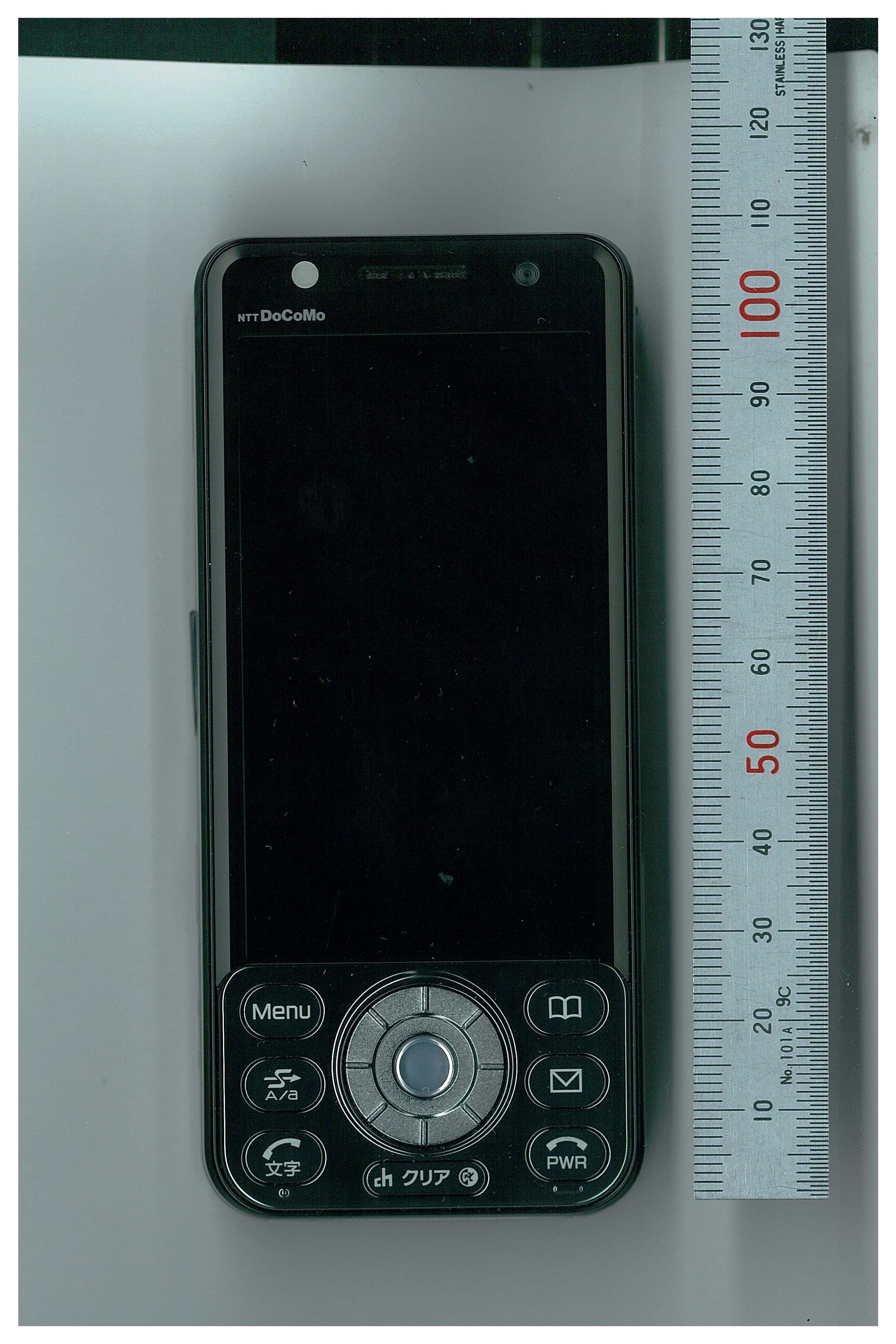
BGBMT0WM07G0R25
Sep 02, 2007GSM/WCDMA Mobile Phone with NFC Function
Equipment Class
DXX - Part 15 Low Power Communication Device Transmitter
BGBX1T502SKE11A01
Aug 31, 2005Smart Keyless System (ECU)
Equipment Class
CYY - Communications Receiver used w/Pt 15 TransmitterBGBX1T412SKE12501
Aug 31, 2005Normal Keyless System (Receiver)
Equipment Class
CYY - Communications Receiver used w/Pt 15 Transmitter