BGBCP-D90DWDigital Color Printer
Mitsubishi Electric Corp
Click to zoom
Application Details
- Equipment Class
- DXX - Part 15 Low Power Communication Device Transmitter
- Date of Grant
- Sep 23, 2015
- Application Purpose
- Original Equipment
- Date of Application
- Sep 23, 2015
- Equipment Note
- Digital Color Printer
- Frequency Range
- 13.56000000 - 13.56000000
- Company
- Mitsubishi Electric Corp
- Country
- United States
Documents & Files
Document Text
Text extracted from the exhibit documents filed with the FCC. Open a document above to read the original.
Users Manual
DIGITAL COLOR PRINTER MODEL CP-D90DW THIS OPERATION MANUAL IS IMPORTANT TO YOU. PLEASE READ IT BEFORE USING YOUR DIGITAL COLOR PRINTER. OPERATION MANUAL Hereby, Mitsubishi Electric Corporation, declares that this digital color printer is in compliance with the essential requirements and other relevant provisions of Directive 1999/5/EC. OTHERS PRECAUTIONS FEATURES PREPARATION TROUBLE- SHOOTING CONTENTS WARNING : TO PREVENT FIRE OR SHOCK HAZARD, DO NOT EXPOSE THIS APPLIANCE TO RAIN OR MOISTURE. CAUTION : TO REDUCE THE RISK OF ELECTRIC SHOCK, DO NOT REMOVE COVER (OR BACK) NO USER-SERVICEABLE PARTS INSIDE REFER SERVICING TO QUALIFIED SERVICE PERSONNEL. RISK OF ELECTRIC SHOCK DO NOT OPEN CAUTION The lightning flash with arrowhead symbol, within an equilateral triangle, is intended to alert the user to the presence of uninsulated “dangerous voltage” within the product’s enclosure that may be of sufficient magnitude to constitute the risk of electric shock. The exclamation point within an equilateral triangle is intended to alert the user to the presence of important operating and maintenance (servicing) instructions in the literature accompanying the appliance. The “Caution, hot surface” symbol indicates that the marked item may be hot and should not be touched. The “Electro Static Discharge (ESD) warning” symbol indicates that trouble (including equipment malfunction) due to static electricity may occur in certain conditions. The “OFF/ON” symbol indicates connection to or disconnection from the mains, at least for mains switches. The “Alternating current” symbol indicates that the equipment is suitable for alternating current only. WARNING: Use the included AC power cord so as not to interfere with radio and television reception. If you use other cables, it may cause interference with radio and television reception. OTHERS PRECAUTIONS FEATURES PREPARATION TROUBLE- SHOOTING CONTENTS CAUTION: Changes or modifications not expressly approved by the party responsible for compliance could void the user’s authority to operate the equipment. NOTE: This equipment has been tested and found to comply with the limits for a Class A digital device, pursuant to Part 15 of the FCC Rules. These limits are designed to provide reasonable protection against harmful interference when the equipment is operated in a commercial environment. This equipment generates, uses, and can radiate radio frequency energy and, if not installed and used in accordance with the instruction manual, may cause harmful interference to radio communications. Operation of this equipment in a residential area is likely to cause harmful interference in which case the user will be required to correct the interference at his or her own expense. This device complies with Industry Canada’s licence-exempt RSSs. Operation is subject to the following two conditions: (1) This device may not cause interference; and (2) This device must accept any interference, including interference that may cause undesired operation of the device. WARNING: In the USA or Canada, use the AC power cord according to the recommendations as below, in order to comply with UL60950-1 and CAN/CSA C22.2 No. 60950-1-03. Connect to the 120 V receptacle of the room or the host equipment. The AC power cord should be UL or CSA approved and consist of type SVT, size 16 or 18AWG, length 2 m or shorter cord with IEC60320-1/C13 type, 125 V 10 A or higher rating connector and NEMA 5-15 type, 125 V 10 A or higher rating plug. Use the AC power cord as specified above, so as not to interfere with radio and television reception. If you use other cables, it may cause interference with radio and television reception. WARNING: In Europe, use the AC power cord according to the recommendations as below, in order to comply with EN60950-1. Connect to the 230 V receptacle of the room or the host equipment. The AC power cord should be VDE approved and consist of core size 0.75 mm 2 or bigger, length 2 m or shorter cord with IEC60320-1/C13 type, 250 V 10 A or higher rating connector and CEE(7)VII type, 250 V 10 A or higher rating plug. Use the AC power cord as specified above, so as not to interfere with radio and television reception. If you use other cables, it may cause interference with radio and television reception. WARNING: The socket outlet shall be installed near the equipment and shall be easily accessible. WARNING: This is a class A product. In a domestic environment this product may cause radio interference in which case the user may be required to take adequate measures. This product is applicable to connect to Norwegian IT power distribution systems. Note: This symbol mark is for EU countries only. This symbol mark is according to the directive 2002/96/EC Article 10 Information for users and Annex IV, and/or to the directive 2006/66/EC Article 20 Information for end-users and Annex II. Your MITSUBISHI ELECTRIC product is designed and manufactured with high quality materials and components which can be recycled and/or reused. This symbol means that electrical and electronic equipment, batteries and accumulators, at their end-of-life, should be disposed of separately from your household waste. If a chemical symbol is printed beneath the symbol shown above, this chemical symbol means that the battery or accumulator contains a heavy metal at a certain concentration. This will be indicated as follows: Hg: mercury (0,0005%), Cd: cadmium (0,002%), Pb: lead (0,004%) In the European Union there are separate collection systems for used electrical and electronic products, batteries and accumulators. Please, dispose of this equipment, batteries and accumulators correctly at your local community waste collection/recycling centre. Please, help us to conserve the environment we live in! PREPARATION FEATURES PRECAUTIONS OTHERS CONTENTS TROUBLE- SHOOTING 1 CONTENTS CONTENTS ...................................................................................................................1 SAFETY PRECA…
Text truncated - open the document above for the full version.
Users Manual
9 OTHERS PRECAUTIONS FEATURES PREPARATION TROUBLE- SHOOTING CONTENTS BEFORE OPERATION PRINTER SETUP PROCEDURE Before printing, follow the printer setup listed below. Position the adjustable paper guides. (See page 10.) Install the print paper to this printer. (See pages 11 to 12.) Install the ink ribbon to this printer. (See pages 13 to 14.) Connect the printer to a personal computer. (See page 16.) Make sure to close the printing unit when the setup procedure is completed. 10 OTHERS PRECAUTIONS FEATURES PREPARATION TROUBLE- SHOOTING CONTENTS BEFORE OPERATION POSITIONING OF ADJUSTABLE PAPER GUIDE Adjust the paper guides according to the paper width. For 9x13(3.5x5”) or 13x18(5x7”) size paper (5”-width) For 10x15(4x6”), 15x20(6x8”) or 15x23(6x9”) size paper (6”-width) Adjustable paper guides HOW TO SET THE ADJUSTABLE PAPER GUIDES Pinch the tab on the adjustable paper guide and slide it right or left. Ta b Slide the paper guide until it stops. The paper guide will snap into place. Slide other paper guide in the similar way. • Make sure to set the adjustable paper guides to the size of the paper width. When they are not positioned properly, a malfunction such as paper jam and misaligned printing position may occur. NOTE • When you use 10x15 (4x6”), 15x20 (6x8”) or 15x23 (6x9”) size paper (having width of 152 mm) after using 9x13 (3.5x5”) or 13x18 (5x7”) size paper (having width of 127 mm) for a long time or printing such paper in large quantities, thermal head cleaning may be required. For cleaning of the thermal head, see page 21. In some cases, the print quality is not improved though thermal head cleaning is carried out. In this case, replacement of the thermal head is required. For detail, consult your dealer. NOTE 11 OTHERS PRECAUTIONS FEATURES PREPARATION TROUBLE- SHOOTING CONTENTS PRINT PAPER INSTALLATION Spacers See the Quick Setup Guide on how to use the spacers. How to attach the spacers 1. Insert the spacer with the paper flange’s stoppers retracted. 2. Turn the spacer until the latches are locked. When you remove the spacers from the paper flanges, follow the above procedure in reverse. Spacer Latch Paper flange BEFORE OPERATION Attach the supplied paper flanges to both sides of the print paper. When you pinch the latches on the paper flange, the stoppers retract into the shaft. Attach the flanges to the print paper with the stoppers retracted. Make sure that the flanges are attached to the print paper securely, and release the latches. • Take care not to pinch your fingers. • Do not remove the sticker on the print paper roll yet. • Do not loosen the paper roll. Any slack in the print paper may degrade the print quality. NOTE • When placing the print paper, keep the print paper upright. • When you put the print paper sideways, it may roll and fall. This may cause injury. CAUTION INCORRECT CORRECT • Fingerprints or dust on the paper’s surface may degrade print quality and cause paper jams. NOTE • When the paper flange cannot be attached due to the deformation of the print paper, reshape the print paper manually before attaching the flange. NOTE Press the POWER switch on the right side panel to turn on the power. Sticker POWER switch 12 OTHERS PRECAUTIONS FEATURES PREPARATION TROUBLE- SHOOTING CONTENTS After the POWER indicator’s color has changed from orange to green, press the OPEN button to release the printing unit out. Remove the paper strip bin and then pull the knob to open the door. Install the print paper into the unit. Place the printing paper in the correct orientation. Make sure the paper roll is firmly installed. • Do not push down on the printing unit or the door. If you push down on the printing unit or the door when they are open, this unit may fall and it can cause damage or injury. CAUTION • Make sure to turn on the power before installing the print paper. Otherwise, a paper jam may occur. • Load the paper roll slowly into the unit. If it is dropped along the ditches, the unit or accessories may be damaged. NOTE Remove the sticker and insert the print paper between the roller and guide as shown right to feed it. When the buzzer sounds, stop the paper feeding. Remove the sticker before inserting the print paper between roller and guide. Make sure to insert the paper straight. Buzzer continues to sound until the printing unit is closed. • Keep the rollers clean. Dirt on the rollers may produce poor print quality. NOTE • When taking the print paper out, pull it up toward you by holding the paper flanges. • Make sure to turn on the power before replacing the print paper. • Make sure to eliminate any slack from the print paper. If you carry out the following steps without eliminating the slack, the print paper may be damaged. NOTE • If you continue to feed the print paper inward after the buzzer sounds, it may cause a paper jam. NOTE Close the door. OPEN button Knob Direction of paper insertion Roller Print paper Guide BEFORE OPERATION 13 OTHERS PRECAUTIONS FEATURES PREPARATION TROUBLE- SHOOTING CONTENTS BEFORE OPERATION INK RIBBON INSTALLATION After installing the print paper, install the ink cassette into this unit. Before installing the ink cassette into this unit, load the ink ribbon in the ink cassette. • Place the ink cassette on a flat surface, when loading the ink ribbon. • Select a place that is free of dust when loading the ink ribbon. Dust or dirt settling on the ink ribbon results in poor print quality. • Make sure that the shafts of the ink ribbon fit into the ink cassette firmly. NOTE Load the ink ribbon in the ink cassette as shown below. Make sure to load it in the correct position. 3 4 12 3 4 12 Ink ribbon Shaft Ink cassette Handle Ditch Make sure to set the ink ribbon roller to the ditches firmly. Turn the shaft to eliminate any slack. Place the ink cassette containing the ink ribbon in the position as shown in the illustration. To insert the ink cassette, align the protrusions on both sides of the cassette with the right and left guides inside the p…
Text truncated - open the document above for the full version.
Users Manual
16 OTHERS PRECAUTIONS FEATURES PREPARATION TROUBLE- SHOOTING CONTENTS BEFORE OPERATION CONNECTION WITH USB DATA SIGNAL EQUIPMENT CONNECTING TO PERSONAL COMPUTER (EXAMPLE) Check that the printer is turned on before connection. Turn on the power of a personal computer. Install the printer driver. • Do not yet connect the printer to a personal computer. NOTE Connect the printer to a personal computer as shown below. To USB port To USB port Personal computerDigital color printer • A USB cable is not supplied with this unit. Use the USB 2.0 certified cable of 2 m or less in length. NOTE PRINTER DRIVER INSTALLATION The printer driver is required to print the data from the personal computer connected with this unit. The printer driver for Windows ® is supplied with this unit. Microsoft and Windows are the trademarks or the registered trademarks of Microsoft Corporation in the U.S.A. and other countries. • Refer to the following website to check the latest version of the printer driver and the printer information. http://www.mitsubishielectric.co.jp/ldg/ja/products/visual/lineup/printer/photo/download_01_english.html NOTE 17 PREPARATION TROUBLE- SHOOTING FEATURES PRECAUTIONS OTHERS CONTENTS ERROR MESSAGES AND COUNTERMEASURES INDICATIONS ON THE FRONT PANEL AND COUNTERMEASURES If, for some reason, printing is not possible or an error occurs during printing, the indicators on the front panel will illuminate or blink. In this case, follow the procedure described below. : Steady on : Off : Blinking ALARMPAPER RIBBONPOWERCauses and CountermeasuresPage (Green) The printer is in the standby mode. 7 (Orange) The printer is in the power save mode. When the printer is idle for an extended period, it automatically enters the power save mode from the standby mode, reducing power consumption. It may take time that the printer is ready to print images after the image data is sent. 7 (Green) The printing unit is open. • Close the printing unit. 7 (Green) The paper strip bin is removed. • Attach the paper strip bin firmly. 7 (Green) A paper jam or a problem concerning the ink ribbon occurs. • Refer to “Overcoming paper jams.” 18 (Green) The printer is receiving image data. The temperature of the thermal head is too high or too low. • Wait until the indication goes off. When the indicator stops blinking, the printer resumes printing automatically. 7 (Green) The ink ribbon which is not available to this printer is installed. • Replace the ink ribbon with a new one. The actual combination of ink ribbon and print paper is inconsistent with the setting made by the personal computer. • Open the printing unit and confirm that the actual combination of ink ribbon and print paper is consistent with the setting made by the personal computer. After checking, close the printing unit. 13-14 (Green) The print paper or ink ribbon is not installed. The print paper or ink ribbon is used up. • Install new print paper or ink ribbon. 11-14 (Green) Other errors 20 When the ALARM or the PAPER RIBBON indicator illuminates or blinks, open the door and carry out the above countermeasures. 18 PREPARATION TROUBLE- SHOOTING FEATURES PRECAUTIONS OTHERS CONTENTS OVERCOMING PAPER JAMS Press the OPEN button to open the printing unit. Make sure that the power is turned on before opening the printing unit. Remove the ink cassette. Remove the paper strip bin and then pull the knob to open the door. Pull out the defective part of the print paper to the direction of an arrow. Cut off the defective part of the print paper with scissors. • Make sure to cut off the printed part of the print paper. Failure to do this may result in the ink ribbon sticking to the print paper and being torn. • Make sure to clean the thermal head and the platen roller. Refer to “CLEANING” (on pages 21 and 22). NOTE Remove the print paper. Install the print paper and the ink cassette with the ink ribbon. (Refer to pages 11-15.) Make sure that the power is turned on before installing the print paper and the ink cassette with the ink ribbon. Close the door. Close the printing unit by pushing it. Attach the paper strip bin. OPEN button Knob ERROR MESSAGES AND COUNTERMEASURES 19 PREPARATION TROUBLE- SHOOTING FEATURES PRECAUTIONS OTHERS CONTENTS REPAIRING A TORN INK RIBBON Position the ink cassette with the torn ink ribbon on a flat, clean surface. Place a piece of transparent adhesive cellophane tape on the center of the ink ribbon. Cellophane tape Direction to turn the shaft Wind the shaft of the ink ribbon in the direction of the arrow so that the cellophane tape is not seen. Install the ink cassette in the printer. ERROR MESSAGES AND COUNTERMEASURES 20 PREPARATION TROUBLE- SHOOTING FEATURES PRECAUTIONS OTHERS CONTENTS ERROR MESSAGES AND COUNTERMEASURES BEFORE CALLING FOR SERVICE For the following symptoms, check the unit again before calling for service. Symptom Check & Remedy The power is not turned on.Is the power cord plug disconnected from the outlet? → Connect the power cord plug to the outlet firmly. → The protective circuit may be working. Turn off the power and wait for about two minutes. Then turn on the power again. The printing unit doesn’t open.Are you turning off the power during printing procedure? → Turn on the power and then open the printing unit. The image is not printed.Is the PAPER RIBBON indicator or the ALARM indicator illuminating or blinking? → Refer to “Overcoming paper jams.” Is the appropriate size of data sent to this unit? → Make sure that the appropriate size of image data is sent to this unit. Is the print paper or the ink ribbon used up? → Check them. Is the printing unit set firmly? → Set the printing unit firmly. → When the indicators keep illuminating or blinking though the above operations are performed, remove the ink ribbon and print paper and reinstall them. An error can not be resolved.→ Turn off and on the power of the printer with the printing unit set firmly. This printer starts initialization. Press the switch inside of the hole …
Text truncated - open the document above for the full version.
Users Manual
21 PREPARATION TROUBLE- SHOOTING FEATURES PRECAUTIONS OTHERS CONTENTS VENTILATION INLET CLEANING Clean the ventilation inlets on the front and both sides of the printer with a vacuum as shown right. THERMAL HEAD CLEANING Press the OPEN button to open the printing unit. Take the ink cassette out of the printer. Preparations Alcohol (ethyl alcohol, etc.) Soft and clean cloth Other : Cleaning ribbon (option)* * Please ask the dealer about options. When lines appear on the printed images, clean the thermal head. Wipe the head cleaning part (as shown right) carefully with cloth dampened with a small amount of alcohol. • Do not damage the thermal head. • When the poor print quality is not corrected even if the head has been cleaned, replacement of the thermal head may be required. Contact your dealer. NOTE Thermal head is hot right after printing. Wait until the head cools before cleaning the thermal head. CAUTION The thermal head may be damaged if you touch it while static electricity builds up on your body. NOTE • When you clean the thermal head, make sure not to apply excessive force to the peeling roller on the bottom of the thermal head. When the excessive force is applied to the roller, the roller may be deformed, resulting in deterioration of the printing quality. NOTE WHEN USING THE CLEANING RIBBON (CR-D70) When you use print paper of 152 mm (6”) width after using that of 127 mm (5”), thermal head cleaning with a cleaning ribbon may be required. If one or two lines appear on the printing surface as shown in the illustration when printing on the print paper of 152 mm (6”) width, clean the thermal head using the optional cleaning ribbon. Print paper of 127 mm(5”) width : 9x13 (3.5x5”), 13x18 (5x7”) Print paper of 152 mm (6”) width : 10x15 (4x6”), 15x20 (6x8”), 15x23 (6x9”) • When the symptom of poor print quality is not corrected even after the head is cleaned, replace the thermal head. Contact your dealer. NOTE Ventilation inlets Ventilation inlet Cleaning part of thermal head Thermal head Peeling roller Printing surface About 12 mmAbout 12 mm Lines 152 mm Cleaning as indicated below will help maintain stable printer operation and extend the printer’s life. Wearing gloves at cleaning is recommended to prevent injury. Make sure to turn off the power before cleaning. CLEANING 22 PREPARATION TROUBLE- SHOOTING FEATURES PRECAUTIONS OTHERS CONTENTS CLEANING PLATEN ROLLER CLEANING Preparations Alcohol (ethyl alcohol, etc.) Soft and clean cloth Clean the black part of the roller. Wipe the black part carefully with cloth dampened with a small amount of alcohol. Wipe the whole roller by turning it. PAPER FLANGE CLEANING Clean the parts that contact the print paper sides as shown right. Wipe the parts carefully with cloth dampened with a small amount of alcohol. Platen roller Cleaning part 23 PREPARATION TROUBLE- SHOOTING FEATURES PRECAUTIONS OTHERS CONTENTS SPECIFICATIONS ClassDigital Color Printer ModelCP-D90DW Printing methodSublimation Dye Thermal Transfer line print 3-color faces progressive printing (yellow, magenta, and cyan) and surface lamination Print’s resolution300 x 300 dpi (dpi : dots per inch) Print size9x13 (3.5x5”) 10x15 (4x6”) 13x18 (5x7”) 15x20 (6x8”) 15x23 (6x9”) 89 x 127mm (without frame) 102 x 152mm (without frame) 127 x 178mm (without frame) 152 x 203mm (without frame) 152 x 229mm (without frame) Gradations256 (8 bits) for each color Supply methodAutomatic InterfaceHi-Speed USB (Ver.2.0) DC output terminals12 V / 2.0 A max. (high priority) 5 V / 2.0 A max. (low priority) Power supply100 - 240 V AC 50/60 Hz Power consumption5.5 A Operating conditionsTemperature : 5°C - 40°C Humidity : 30% - 80% RH (no dewing) Installation conditionsOperating attitude : Horizontal ±5° Outside dimensions276 (W) x 367 (D) x 238 (H) mm WeightApprox. 14 kg (excluding accessories) Standard accessoriesPower cords (for 120 V and 230 V), Ink cassette (1), CD-ROM (1), Paper flange (1 set), Spacers (2), Quick setup guide (1), Paper strip bin (1), Paper tray (1), Cable tie (2), Securing band (1), Screw for securing band (2), Washer (1) Print size and outside dimensions show typical value. Design and specifications are subject to change without notice. Contents of CD-ROM • Operation manual MITSUBISHI ELECTRIC EUROPE B.V. UK Branch Travellers Lane, Hatfield, Herts. AL10 8XB, England, U.K. Phone +44 (0) 1707 276100 FAX +44 (0) 1707 278755 German Branch Gothaer Strasse 8, 40880 Ratingen ; Postfach 1548, 40835 Ratingen ; Germany Phone +49 (2102) 486-9250 FAX +49 (2102) 486-7320 French Branch 25, Boulevard des Bouvets - 92741 NANTERRE cedex, France Phone +33 (1) 55 68 55 00 FAX +33 (1) 55 68 57 31 Benelux Branch Nijverheidsweg 23a, 3641 RP Mijdrecht, The Netherlands Phone +31 (0) 297-282461 FAX +31 (0) 297-283936 Spanish Branch (Barcelona) Ctra. de Rubí, 76-80 - Apdo. 420 08190-Sant Cugat del Vallés - (Barcelona) Spain Phone +34 93 565 3154 FAX +34 93 589 4388 Manufactured by Mitsubishi Electric (Malaysia) Sdn. Bhd. PLO 32, Kawasan Perindustrian Senai II, 81400 Senai, Johor Darul Takzim, Malaysia Please contact the nearest Mitsubishi sales branch to get DOC (Declaration of Conformity) of the EC Directive 1999/5/EC. WE919C194A2 MITSUBISHI ELECTRIC US. INC. Visual and Imaging Systems 5900-A Katella Ave. Cypress, CA 90630-5019, U.S.A. Phone 888-307-0309
External Photos
External Photo Mitsubishi Electric Corporation Kyoto Works Digital Color Printer [Model: CP-D90DW] Front Back External Photo Mitsubishi Electric Corporation Kyoto Works Digital Color Printer [Model: CP-D90DW] Side (Right) Side (Left) External Photo Mitsubishi Electric Corporation Kyoto Works Digital Color Printer [Model: CP-D90DW] Top Bottom Color Production prototype: White Mass-produced items: Black
Internal Photos
Internal Photo Mitsubishi Electric Corporation Kyoto Works Digital Color Printer [Model: CP-D90DW] Antenna Location Internal Photo Mitsubishi Electric Corporation Kyoto Works Digital Color Printer [Model: CP-D90DW] Internal Photo Mitsubishi Electric Corporation Kyoto Works Digital Color Printer [Model: CP-D90DW] Digital Board (Top) Digital Board (Bottom) Internal Photo Mitsubishi Electric Corporation Kyoto Works Digital Color Printer [Model: CP-D90DW] Antenna Board (Top) Antenna Board (Bottom)
Test Report
Test report No. : 10874229H-A-R1 Page : 2 of 22 FCC ID : BGBCP-D90DW Issued date : September 1, 2015 Revised date : September 16, 2015 UL Japan, Inc. Ise EMC Lab. 4383-326 Asama-cho, Ise-shi, Mie-ken 516-0021 JAPAN Telephone : +81 596 24 8999 Facsimile : +81 596 24 8124 REVISION HISTORY Original Test Report No.: 10874229H-A Revision Test report No. Date Page revised Contents - (Original) 10874229H-A September 1, 2015 - - 1 10874229H-A-R1 September 16, 2015 P.5 Update to FCC version 1 10874229H-A-R1 September 16, 2015 P.5 Correction of margin for Conducted emission 1 10874229H-A-R1 September 16, 2015 P.13, 14 Correction of Conducted emission data 1 10874229H-A-R1 September 16, 2015 P.13 Correction of note sentence 1 10874229H-A-R1 September 16, 2015 P.15 Correction of Fundamental emission and Spectrum Mask data 1 10874229H-A-R1 September 16, 2015 P.15 Deletion of note sentence Test report No. : 10874229H-A-R1 Page : 3 of 22 FCC ID : BGBCP-D90DW Issued date : September 1, 2015 Revised date : September 16, 2015 UL Japan, Inc. Ise EMC Lab. 4383-326 Asama-cho, Ise-shi, Mie-ken 516-0021 JAPAN Telephone : +81 596 24 8999 Facsimile : +81 596 24 8124 CONTENTS PAGE SECTION 1: Customer information ............................................................................................. 4 SECTION 2: Equipment under test (E.U.T.) ............................................................................... 4 SECTION 3: Test specification, procedures & results ................................................................ 5 SECTION 4: Operation of E.U.T. during testing ........................................................................ 8 SECTION 5: Conducted emission ............................................................................................... 10 SECTION 6: Radiated emission (Fundamental , Spurious Emission and Spectrum Mask) . 11 SECTION 7: Other test ................................................................................................................ 12 APPENDIX 1: Data of EMI test .................................................................................................. 13 Conducted emission ........................................................................................................ 13 Fundamental emission and Spectrum Mask ................................................................ 15 Spurious emission ........................................................................................................... 16 20dB Bandwidth and 99% Occupied Bandwidth ........................................................ 18 Frequency Tolerance ...................................................................................................... 19 APPENDIX 2: Test instruments .................................................................................................. 20 APPENDIX 3: Photographs of test setup.................................................................................... 21 Conducted emission ........................................................................................................ 21 Radiated emission ........................................................................................................... 22 Test report No. : 10874229H-A-R1 Page : 4 of 22 FCC ID : BGBCP-D90DW Issued date : September 1, 2015 Revised date : September 16, 2015 UL Japan, Inc. Ise EMC Lab. 4383-326 Asama-cho, Ise-shi, Mie-ken 516-0021 JAPAN Telephone : +81 596 24 8999 Facsimile : +81 596 24 8124 SECTION 1: Customer information Company Name : Mitsubishi Electric Corporation Kyoto Works Address : 1 Zusho Baba Nagaokakyo-City Kyoto, 617-8550 Japan Telephone Number : +81-75-958-3249 Facsimile Number : +81-75-958-3709 Contact Person : Tatsuya Egawa SECTION 2: Equipment under test (E.U.T.) 2.1 Identification of E.U.T. Type of Equipment : Digital Color Printer Model No. : CP-D90DW Serial No. : Refer to Clause 4.2 Rating : AC 100-240 V, 50/60 Hz Receipt Date of Sample : August 5, 2015 Country of Mass-production : Malaysia Condition of EUT : Production prototype (Not for Sale: This sample is equivalent to mass-produced items.) Modification of EUT : No Modification by the test lab 2.2 Product Description General Specification Clock frequency(ies) in the system : 2.0 GHz (max.) Mechanical driving: 60 MHz Radio Specification Radio Type : Transceiver Frequency of Operation : 13.56 MHz Modulation : ASK (ISO15693) Bandwidth : 140 kHz Power Supply (radio part input) : DC 5.0 V Antenna Type : Loop coil Antenna Connector Type : Board to wire connector Method of Frequency Generation : Quartz Crystal Test report No. : 10874229H-A-R1 Page : 5 of 22 FCC ID : BGBCP-D90DW Issued date : September 1, 2015 Revised date : September 16, 2015 UL Japan, Inc. Ise EMC Lab. 4383-326 Asama-cho, Ise-shi, Mie-ken 516-0021 JAPAN Telephone : +81 596 24 8999 Facsimile : +81 596 24 8124 SECTION 3: Test specification, procedures & results 3.1 Test Specification Test Specification : FCC Part 15 Subpart C: 2015, final revised on September 8, 2015 Title : FCC 47CFR Part15 Radio Frequency Device Subpart C Intentional Radiators Section 15.207 : Conducted limits Section 15.225 : Operation within the band 13.110-14.010MHz * The revision on September 8, 2015 does not affect the test specification applied to the EUT. 3.2 Procedures and results Item Test Procedure Specification Worst margin Results Remarks Conducted emission ANSI C63.4:2009 7. AC powerline conducted emission measurements Section 15.207 / 15.107(b) [QP] 19.6 dB 13.56000 MHz, N [AV] 10.0 dB 15.96556 MHz, N Complied- <IC>RSS-Gen 8.8 <IC>RSS-Gen 8.8 Electric Field Strength of Fundamental Emission ANSI C63.4:2009 13. Measurement of intentional radiators Section 15.225(a) 80.3 dB 13.56000 M…
Text truncated - open the document above for the full version.
Contact Information
Applicant
Richard Gruhlke(Principal Compliance Engineer)
Technical Contact
UL Japan, Inc.Takayuki Shimada
[email protected]81-596-24-8124
4383-326 Asama-cho, Ise-shi · Mie-ken · Japan
Test Firm
UL Japan, Inc. Head office EMC Lab.Tetsuya Hashimoto
Technical Specifications
| # | Rule Parts | Frequency Range | Power Output |
|---|---|---|---|
| 1 | 15C | 13.56 MHz - 13.56 MHz | - |
Other Applications from Mitsubishi Electric Corp

BGBCP-C60DW
Jan 22, 2014Digital Color Printer
Equipment Class
DXX - Part 15 Low Power Communication Device Transmitter
BGBCP-D70DW
Jul 22, 2010Digital Color Printer
Equipment Class
DXX - Part 15 Low Power Communication Device Transmitter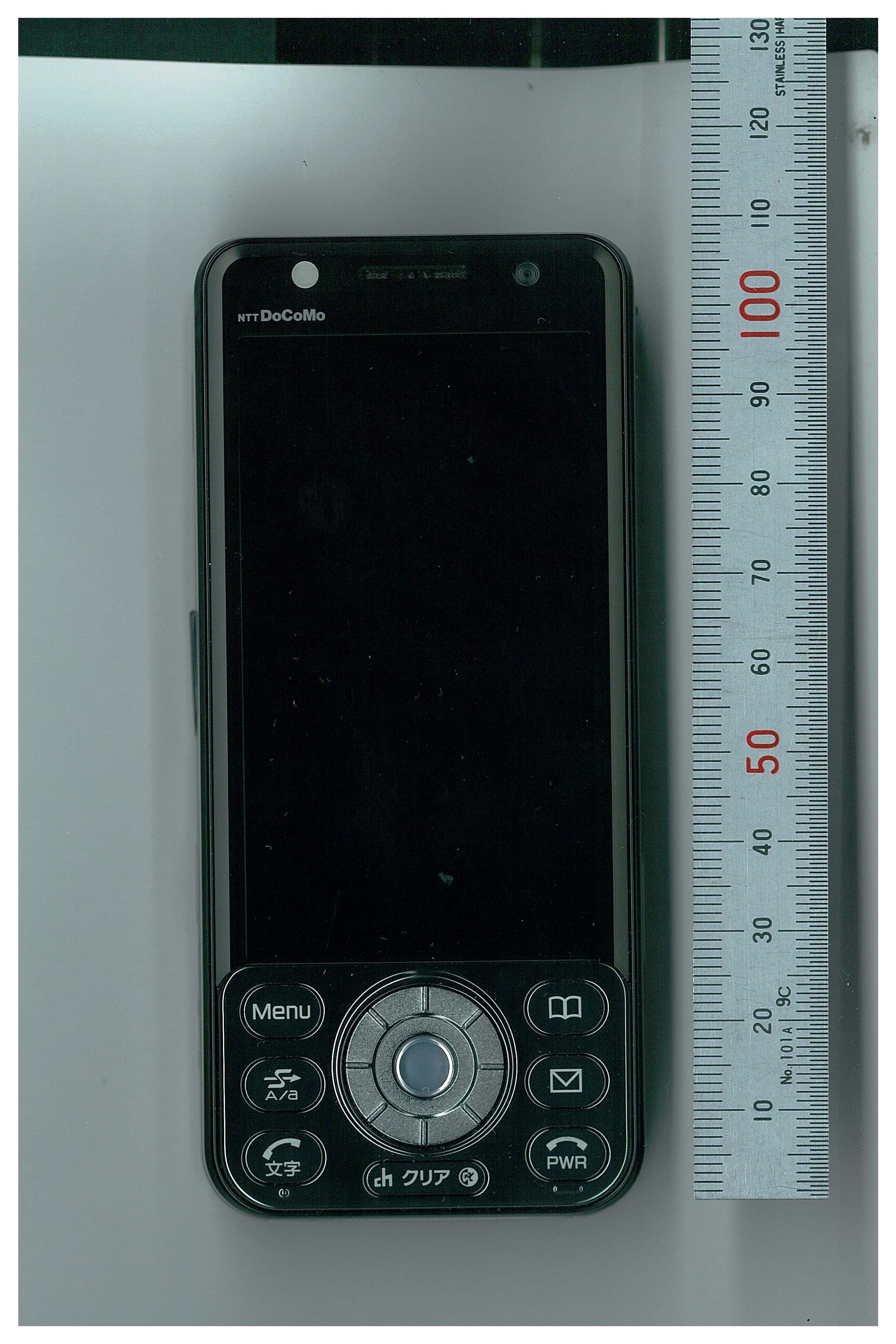
BGBMT0WM07G0R25
Sep 02, 2007GSM/WCDMA Mobile Phone with NFC Function
Equipment Class
DXX - Part 15 Low Power Communication Device Transmitter
BGBX1T502SKE11A01
Aug 31, 2005Smart Keyless System (ECU)
Equipment Class
CYY - Communications Receiver used w/Pt 15 TransmitterBGBX1T412SKE12501
Aug 31, 2005Normal Keyless System (Receiver)
Equipment Class
CYY - Communications Receiver used w/Pt 15 Transmitter