BIB54505001-01Meteor Burst Packet Data Radio For Fixed Or Mobile
Meteorcomm LLC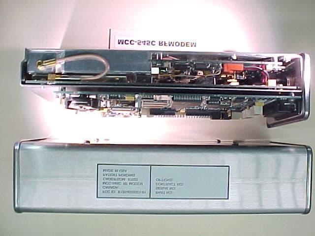
Click to zoom
Application Details
- Equipment Class
- LMS - Part 90 Location & Monitoring Transmitter
- Date of Grant
- May 06, 2001
- Application Purpose
- Original Equipment
- Date of Application
- Jan 22, 2001
- Equipment Note
- Meteor Burst Packet Data Radio For Fixed Or Mobile
- Frequency Range
- 36.00000000 - 50.00000000
- Company
- Meteorcomm LLC
- Country
- United States
Documents & Files
Document Text
Text extracted from the exhibit documents filed with the FCC. Open a document above to read the original.
Users Manual
FCC ID: BIB5450500101 EXHIBIT VIII OPERATION AND MAINTENANCE OF THE MCC-545C PACKET DATA RADIO FCC ID: BIB5450500101 EXHIBIT VIII OPERATION AND MAINTENANCE OF THE MCC-545C PACKET DATA RADIO MAN-OM-545C January 2001 Meteor Communications Corporation 8631 So.212th St.. Kent, WA 98031 Tel: (253) 872-2521 Fax: (253) 872-7662 E-mail: [email protected] 2000 by Meteor Communications Corporation all rights reserved FCC ID: BIB5450500101 EXHIBIT VIII This page MUST be inserted for any copy of this manual going to the United Kingdom. WARNING WARNING WARNING Certain power transistors used in this equipment and their associated heatsink components are manufactured partly or wholly from a beryllium compound. Normally these can be handled without risk of toxicity, but there is a toxic hazard if dust or finely-divided particles of the material are inhaled or enter the body through a cut. Consequently, great care must be taken, and hands must be washed after handling. Any cuts or abrasions on the hands must be covered by dressings while such components are being handled. If beryllium dust does enter the skin through a cut or abrasion, the affected part must be washed thoroughly and treated by a doctor. Components containing beryllium may only be machined, cut, abraded, or heated above 400 C under strictly controlled conditions approved by the appropriate Safety Authority. Disposal of Beryllium Disposal of faulty components must be carried out according to special arrangements. Should a component containing Beryllium be broken, its parts and particles must be gathered carefully using a moistened tissue (preferably while wearing plastic or rubber gloves), placed in a plastic bag together with any contaminated materials, sealed, labeled, and disposed of in a manner approved of by the Safety Authority. Beryllium Components in MCC-545C RF Power Components RF power components in the modules listed below incorporate some Beryllium within the transistor package and must be handled as specified in the above warning notice. TRANSISTOR CIRCUIT MODULEMANUFACTURERREFERENCE 545C 100W Transmitter (54505302-01) Advanced Semi Corp Motorola Q1,Q4 Q2 FCC ID: BIB5450500101 EXHIBIT VIII GENERAL WARRANTY Meteor Communications Corporation (MCC) warrants that its products conform to the published specifications and are free from manufacturing and material defects for one year after shipment. Warranty-covered equipment that fails during the warranty period will be promptly repaired at MCC’s facility in Kent, Washington. International customers shall pay shipping costs to the MCC facility, with Seattle as the point of U.S. entry. MCC shall pay incoming U.S. duty fees. MCC shall pay for shipping costs to return the equipment to the customer, with the customer paying any and all return duty fees. This warranty is contingent upon proper use of the equipment and does not cover equipment that has been modified in any way without MCC’s approval or has been subjected to unusual physical or electrical stress, or on which the original identification marks have been removed or altered. FCC ID: BIB5450500101 EXHIBIT VIII REVISION PAGE Document TitleMCC-545C INSTALLATION AND OPERATIONS Manual Document Number: Revision #DateRevision Redline11/10/2000Redline Release 01/03/2001Initial Release A B C D E F G H I DESCRIPTION 2-1 O&M of the MCC-545C PACKET DATA RADIO 12/2000 TABLE OF CONTENTS Title Page 1.0INTRODUCTION ................................................................................................... 1-1 1.1 Organization ..................................................................................................... 1-1 1.2 Support Documents .......................................................................................... 1-2 1.3 Conventions...................................................................................................... 1-2 2.0DESCRIPTION ....................................................................................................... 2-1 2.1 General Description............................................................................................. 2-1 2.2 Send and Receive Messages................................................................................ 2-1 2.3 Data Logging....................................................................................................... 2-1 2.4 Position Location................................................................................................. 2-2 2.5 Maintenance Features.......................................................................................... 2-3 2.6 Hardware Organization and Layout .................................................................... 2-3 2.6.1 MCC-545C Transceiver Assembly ......................................................... 2-4 2.6.2 MCC-545C Power Amplifier .................................................................. 2-7 2.6.3 MCC-545C Microprocessor .................................................................... 2-7 3.0INSTALLATION .................................................................................................... 3-1 3.1 Site Selection ...................................................................................................... 3-1 3.1.1 External Noise/Interference .................................................................... 3-1 3.1.2 Horizon Angle ......................................................................................... 3-3 3.1.3 Power Source........................................................................................... 3-3 3.1.4 Site Dimensions....................................................................................... 3-3 3.1.5 Antenna Considerations .......................................................................... 3-3 3.2 Equipment Installation........................................................................................ 3-5 3.2.1 Antenna Installation ........................…
Text truncated - open the document above for the full version.
Cover Letter(s)
January 25, 2001 Federal Communications Commission Authorization and Evaluation Division 7435 Oakland Mills Rd. Columbia, MD 21046 Re: FCC ID’s : B1B54505001-01 & B1B54506001-01 Applicant: Meteor Communications Corporation Gentlemen: Under the provisions of CFR 47, Part 0.459 Meteor Communications Corporation, (MCC) requests that Exhibits listed below, for the above referenced Certification application, are with held from public viewing. The reason for withholding the information under Part 0.457 (d) is cited as trade secrets. MCC considers this information proprietary in nature and asks that the Exhibits be treated in a confidential manner and not made available to the general public. Release of such information could result in serious financial harm and a loss of company proprietary information. Exhibit IVBlock Diagrams Exhibit VSchematics Diagrams and Transmitter Expository Statement Exhibit XTune Up Procedures If you have any questions concerning this request please feel free to call the undersigned 253 872-2521 or Rod Munro 425 771-4482. Regards, Tom Donich VP Engineering 8631 South 212th Street Kent, Washington 98031 USA METEOR COMMUNICATIONS CORPORATION Tel: 253/872-2521 Fax: 253/872-7662 Email: [email protected] Web: www.meteorcomm.com
External Photos
Applicant: Meteor Communications CorporationFCC ID: BIB54505001-01 EXHIBIT 3 Exhibit III. External Photographs Photo 1. Top view cover on FCC ID Label location and removed See FCC Label below. FCC ID: BIB54505001-01PART NO: CANADA: SERIAL NO: MCC-545C RF MODEMCONTRACT NO: 1.3” CAGE/FSCM: 67022OPTIONS: PATENT PENDING MADE IN USA This device complies with Part 15 of the FCC rules. Operation is subject to the condition that this device does not cause harmful i nterference. 4.0” Photo 2. External view Photo 3. End plate (same plate for MCC545B and MCC545C except for the Model number). Applicant: Meteor Communications CorporationFCC ID: BIB54505001-01 EXHIBIT 3
ID Label/Location Info
Applicant: Meteor Communications Corporation FCC ID: BIB54505001-01 Exhibit 1 LIST OF EXHIBITS DESCRIPTIO NEXHIBITSREFERENCE I.Identification label Information12.1033 (c) 11 & 2.925 & General Information1A 1. Production Plans2.1031 2. Application References2.1061 3. Data submittal Procedure 4. Similar Certified Transmitter II.Certification Data2 III.External Photographs32.1033 (c) 12 IV.Block Diagrams (Circuit Diagrams)42.1033 (c) 10 V.Schematic Diagrams52.1033 (c) 10 VI.Test Report6 1. Data Index6 2. RF Output Data6A 2.1046 3. Modulation Characteristics2.1047 A. Audio Response & Low Pass Filter ResponseN/A data only B. Modulation LimitingN/A data only 4. Occupied Bandwidth6E2.1049 5. Cond ucted Sp urio us E miss io ns6F2.1051 6. Radiated Spurious Emissions6G2.1053 7. Frequency Stability (Temperature & Supply Voltage)6H 2.1055 VII.Test Set-up Procedures72.1041 VIII.Instruction Manual82.1033 (c) 3 IX.Internal Photographs92.1033 (c) 12 X.Tune Up Procedures102.1033 (c) 9 XI.RF Exposure Information112.1093 XII.Operational Description122.1033 (c) 1, 2, 4, 5, 6, 7, 2.1033 (c) 8, 13 1. Technical Characteristics 1 - 5 2. Application XIII. Cover Letter13 Applicant: Meteor Communications Corporation FCC ID: BIB54505001-01 Exhibit 1 EXHIBIT I. IDENTIFICATION LABEL ----- 47 CFR. 2.1033(C) 11 LOCATION Top side of the transceiver unit chassis. Photo follows. TYPE Label Material: Silver Matte Mylar #7222 Clear Matte Imprintable Mylar Overlay #PM-200-CM/T Adhesive:Permanent, pressure activated Process:Hot Stamp Thickness:4mils total Color:Black Lettering Actions:Laminate Diecut Strip Waste MARKINGS (TEXT) View of FCC portion of label : Source Control Drawing FCC ID: BIB54505001-01PART NO: CANADA: SERIAL NO: MCC-545C RF MODEMCONTRACT NO: 1.3” CAGE/FSCM: 67022OPTIONS: PATENT PENDING MADE IN USA This device complies with Part 15 of the FCC rules. Operation is subject to the condition that this device does not cause harmful i nterference. 4.0” Applicant: Meteor Communications Corporation FCC ID: BIB54505001-01 Exhibit 1 FCC ID LABEL LOCATION Applicant: Meteor Communications Corporation FCC ID: BIB54505001-01 Exhibit 1 Exhibit 1A. General Information --- 47 CFR 2.1031 and 2.1061. 1A.1. Production Plans --- Pursuant 47 CFR 2.1031 Quantity production is planned. 1A.2. Application References --- Pursuant 47 CFR 2.1061 Reference is made to the following MCC "Application References" 1. Land Mobile Products and their application 1A.3. Data Submittal Procedure Data located in Exhibit 6 is supplied in accordance with Part 2, Sub-part J and Part 90, Sub-parts I and J of the Commission’s rules and will be submitted electronically. 1A.4. Similar, currently Type Accepted Transmitter The Model: MCC545A, manufactured by Meteor Communications Corporation was Certified under the FCC ID: BIB54503002-03 on May 13, 1997.
Internal Photos
Applicant: Meteor Communications CorporationFCC ID: BIB54505001-01 Exhibit 9 Exhibit IX Internal Photographs MCC545C Photo 1.Side view of case closed and open with side view of PCB in place. Photo 2. Top and bottom view of transmitter board with shield removed. Photo 3.Top and bottom view of receiver board. Photo 4.Top and Bottom view of CPU board. Applicant: Meteor Communications CorporationFCC ID: BIB54505001-01 Exhibit 9 Applicant: Meteor Communications CorporationFCC ID: BIB54505001-01 Exhibit 9
Operational Description
Applicant: Meteor Communications CorporationFCC ID: BIB54505001-01 Exhibit 12 Exhibit 12 Operational Description Information required by Section 2.1033(c) 1 - 14 1. The Applicant and Manufacturer is: Meteor Communications Corporation 8631 South 212 th Street Kent, WA 98031 2. FCC ID: BIB54505001-01 3. Please refer to Exhibit VIII 4. Emission Designator: 11K5G1D 5. Frequency Range: 36 – 50 MHz 6. Range of Power: Output power is not variable 7. Maximum power rating: 100 Watts at 12 VDC 8. Please refer to Exhibit X for details 9. Please refer to Exhibit X 10. Please refer to Exhibit V 11. Please refer to Exhibits I 12. Please refer to Exhibits III and IX 13. Please refer to Exhibit X 14. Please refer to Exhibit VI containing the requirements of Section 2.1046 through 2.1057 inclusive. Applicant: Meteor Communications CorporationFCC ID: BIB54505001-01 Exhibit 12 Additional Technical Information 1. Technical Characteristics 1a.) Technical description: The MCC545C Packet Data Radio utilizes GMSK modulation at 9600 bps. 1b.) Transmitter Application: The transceiver can be used for sending and receiving messages, position reporting, data logging, or other specific applications. Designed to operate over a fading ground wave and an intermittent meteor burst communications channel. The MCC545C provides full text message capabilities in either plain text or binary data and can be routed to exchange messages with other single or multiple destinations or to a host computer or data center. 1c.) Power Supply Available: none, requires a 12 VDC nominal (10-14 VDC) 1d.) Antenna available: MCC purchase commercially available antenna’s from antenna vendors. The antenna recommended by MCC’s engineering staff will vary depending on site conditions. 1e.) Data Cables Available: 1.) MCC P/N 14001352-01 interface cable 1f.) Housing: The transmitter is housed in a rugged weather-resistant stainless steel enclosure 10.6’ X 4.0” X 2.42”, weighing less than 3 pounds.
RF Exposure Info
HUMAN EXPOSURE TO RADIO FREQUENCY ELECTROMAGNETIC FIELDS WITH MCC 545C/B RADIOS ENGINEERING STATEMENT 4/13/01 TX Duty Cycle AND Tx power The MCC 545B/C radios operate in the low band VHF frequency region (37-50 MHz), with maximum transmit power levels of 100 watts, and with a maximum TX duty cycle of 10%. The Packet Data Radio is operated in ½ duplex using a solid state PIN diode T/R switch. Maximum TX time and duty cycle is governed by the RF protocols used to transmit and receive RF packets. The maximum transmission time for any packet is limited to less than 100-milli sec. Most frames are ½ of this. Typical duty cycles are less than 1 % (transmit a position report (every 30 seconds) or weather data report (every 5 minutes). To prevent the transmitter from over heating software in the control processor limits the maximum number of transmissions in a fixed period of time (typically 2 –3 seconds) such that the maximum duty cycle is less than 10%. This duty cycle limit effectively reduced (for purposes of the MPE calculation) the average transmitted RF power to 10 watts or less. Calculations of MPE (Maximum Permitted Exposure) Distance The FCC guidelines limit the maximum permitted exposure for Occupational/Controlled Exposure to 1 mw/sq. cm for frequency ranges of 30-300 MHz. This limit and the following equation for calculating field strength (obtained from OET Bulletin 65) is used to calculate the minimum separation between humans and the transmit antenna based on MPE S= P*G* DC/(4*π ππ π*R*R) P = Transmit power in milliwatts = 100,000 G = Antenna gain referenced to an isotropic radiator = 1.68 (2.2dbi) mobile quarter wave dipole mounted to fender or roof of automobile = 10.0 (10.0 dbi) fixed 5 element yagi mounted to top of fixed antenna tower = 3.3 (5.2 dbi) fixedhalf wave dipole mounted to fixed antenna tower leg R = separation required cm DC= Maximum duty cycle of transmitter = 10 % S = Power density = 1 milliwatt/square cm This equation is accurate for the far field of an antenna, but will over-predict power density in the near field. Thus, the near field MPE distances calculated here are “worst case” or conservative. Mobile applicationR= .36 meters (14 inches) with quarter wave dipole Fixed applicationsR= .90 meters with 5 element yagi R= .52 meters with side mount half wave dipole Proposed manual wording The mobile applications: The antenna used for mobile application must have a maximum antenna gain of less than 2.2 dbi (¼ wave dipole or ½ wave dipole) and must be mounted such that the separation between the antenna and any human occupants of the vehicle exceeds .36 meters (14”). The best location for antenna mounting is the center of the vehicle roof. This will provide additional RF shielding between the antenna and the human occupants that reduces the RF exposure to levels well below that specified in FCC OET Bulletin 65. When working on the antenna and or co-ax cable always disable the transmitter by turning its power off. For fixed applications For fixed applications, antenna gains and mounting techniques can vary depending on the application. For Yagi antennas whose gain does not exceed 10 dbi, that antenna must be mounted a minimum of .90 meters from any humans occupants. Lower gain antennas, such as side mount dipoles, exhibit lower gain (5.2 dbi) allow closer separations (.52 meters for 5.2 dbi antennas). This will provide RF shielding between the antenna and the human occupants that reduce the RF exposure to levels below that specified in FCC OET Bulletin 65. When working on the antenna and or co-ax cable always disable the transmitter by turning its power off. Antenna Specs The enclosed JPEG files give the specifications for the various antennas that can be used in the mobile and in the fixed applications. MOBILE ANTENNAS - QUARTER WAVE LOADED (UNITY GAIN) MNO SERIES ¾” HOLE MOBILE ANTENNAS - QUARTER WAVE LOADED (UNITY GAIN) MNO SERIES ¾” HOLE MOBILE ANTENNAS ¼ WAVE LOADED UNITY GAIN MOBILE ANTENNAS (MARINE) DIPOLE END FED UNITY GAIN FIXED STATION ANTENNAS (DIPOLE SIDE MOUNT DB-212-1 & DB212-2) FIXED STATION ANTENNA PATTERNS (DIPOLE SIDE MOUNT DB-212-1 & DB212-2) FIXED STATION ANTENNAS (2,3 AND 5 ELEMENT YAGI’S) FIXED STATION ANTENNA PATTERNS & SPECS (2,3,AND 5 ELEMENT YAGI’S)
Test Report
EXHIBIT VI Application For CERTIFICATION Measurement Data Prepared On Behalf Of METEOR COMMUNICATIONS CORPORATION FCC ID: BIB54505001-01 Model: MCC545C VHF Low Band - Meteor Burst Packet Data Radio Under Part 90 BY Spectrum Technology, Inc. 209 Dayton Street Edmonds, WA 98020 425 771-4482 January 22, 2001 EXHIBIT VI CERTIFICATION TABLE OF CONTENTS Exhibit 6A - RF Output Data (2.1046)1 Exhibit 6B - Modulation Characteristics (2.1047)N/A Exhibit 6E - Occupied Bandwidth (2.1049)2 – 4 Exhibit 6F - Conducted Spurious Emissions at Antenna Terminals (2.1051)5 - 6 Exhibit 6G - Radiated Spurious Radiation (2.1053)7 Exhibit 6H - Frequency Stability Performance (2.1055)8 - 9 EXHIBIT VI EXHIBIT 6A - TEST: RF POWER OUTPUT FCC ID:BIB54505001-01 Grantee:Meteor Communications Corporation Serial No.:none Manufacture Rating:100.0 Watt +50 dBm Equipment Authorization Procedure:Para. 2.1046 Duty Cycle:Intermittent Packet Data Frequency Measured:45.00 MHz FINAL RADIO FREQUENCY AMPLIFYING DEVICE Transistor Type: Advanced Semi Corp.VLB100-12F (Q1) Measured Power Output 100.0 Watt or + 50 dBm Page 1 EXHIBIT VI EXHIBIT 6E - TEST: OCCUPIED BANDWIDTH FCC ID:BIB54505001-01 Grantee:Meteor Communications Corporation Serial No.:none Minimum Standard Specified:Para. 90.210(c) Test Results:Equipment complies with standard Equipment Authorization Procedure:Para. 2.1049 The modulation generated by the EUT and used during test was a pseudo random GMSK data modulation at 9600 bits/sec. This is the maximum amplitude and symbol rate. MEASUREMENT DATA Spectrum Analyzer: Hewlett Packard 8562A Plot APlot B Settings:Resolution Bandwidth: 300 300 Hz Video Filter:300300Hz Scan Time: 5 3 sec. Scan Width: 50 100kHz Center Frequency:45.0045.00MHz Please refer to the following two pages for the Plots A and B referenced above for the occupied bandwidth measured. Page 2 EXHIBIT VI EXHIBIT 6F - TEST: CONDUCTED SPURIOUS EMISSIONS FCC ID: BIB54505001-01 Grantee:Meteor Communications Corporation Serial No.:none Minimum Standard Specified:Para. 90.209 Test Results:Equipment complies with standard Equipment Authorization Procedure:Para. 2.1051 Frequency Range Observed:0 to 500 MHz Operating Frequency:45.00 MHz Power Output:100.0 Watt high power (peak) Spurious Limit = 43 dB + 10Log 10 PO = 43 + (20) = 63 dBc Method of Measurement The transmitter output was fed through a tuneable bandpass filter, a K&L Microwave Model:X4BT-75/150-2B, tuned individually to permit the second then the third harmonic and so on, to pass, while the Fo was rejected. The bandpass filter was used to allow an accurate measurement and avoid overloading the mixer of the spectrum analyzer due to the high power. The spectrum analyzer plot on the following page is a max-hold peak record. The modulation generated by the EUT and used during test was a pseudo random GMSK data modulation at 9600 bits/sec. This is the maximum amplitude and symbol rate. Please refer to the plot on the following page with the measurement results. Page 5 EXHIBIT VI EXHIBIT 6G - TEST: RADIATED SPURIOUS EMISSIONS FCC ID: BIB54505001-01 Grantee:Meteor Communications Corporation Serial No.:none Minimum Standard Specified:Para. 90.210 Test Results:Equipment complies with standard Equipment Authorization Procedure:Para. 2.103 Test Equipment Set Up:See Block Diagram Frequency Range Observed:0 to 500 MHz Operating Frequency:45.00 MHz Power Output:100.0 Watt (peak) Spurious Limit = 43 dB + 10Log 10 PO = 43 + (20) = 63 dBc high power The modulation generated by the EUT and used during test was a pseudo random phase shift key (PSK) data modulation. The data stream is a 2kHz square wave or 4 kb/sec. data rate. This is the maximum amplitude and symbol rate. FORMULAFREQUENCY IN MHzLevel (dB below carrier) Fo45.00- 0 - 5Fo225.00 - 90.66 Note: All radiated emissions measured were more than 20 dB below the spurious limits noted above with 5Fo the highest level measured. Page 7 EXHIBIT VI EXHIBIT 6H - FREQUENCY STABILITY FCC ID:BIB54505001-01 Grantee:Meteor Communications Corporation Minimum Standard Specified:Para. 90.213-30 to +50 C 20 ppm = +/- 900 Hz25-50 MHz Equipment Authorization Procedure:Para. 2.995 Test Frequency:45.00 MHz Test Results:Equipment complies with standard The measurement data reported on the following page, displays the frequency observed when the transmitter was first keyed, immediately following power up (a period of 45-60 seconds). This value was recorded and is reported. Measurements at +50, 0 and -30 degrees C were made at the nominal voltage and after varying the voltage + and - 15 %. Within the initial 60 seconds, the transmitter was measured well within the frequency tolerance of 20 ppm in all cases. Two temperature probes connected to a Fluke 52, were used during the measurements. The first probe was mechanically held in place in contact with the largest internal mass of the transmitter adjacent to the TCXO. The other probe was placed within the chamber at a location with good air circulation to accurately measure the internal chamber temperature for comparison with the internal transmitter temperature to ensure temperature stability at all measurement points prior to measurements. Voltages used for measurements at -30, 0, & +50 degrees Celsius: +15 % 13.8 VDC Nominal12.0 VDC -15%10.2 VDC Page 8 EXHIBIT VI EXHIBIT 6H - FREQUENCY STABILITY FCC ID: BIB54505001-01Grantee: Meteor Communications Corporation Minimum Standard Specified:Para. 90.213-30 to +50 C 20 ppm = +/- 900 Hz 25-50 MHz Equipment Authorization Procedure:Para. 2.1055 Test Frequency:45.00 MHz Band 36 - 50 MHz The variation in frequency with voltage are shown on the plot above for +50, 0 and -30 C. Three readings are shown at these temperatures. The left hand reading is -15%, 10.2 VDC, the right hand reading is +15%, 13.8 VDC. The center reading at +50, 0 and 30 degrees C and all of the other reported readings are at the nominal voltage of 12 VDC. Page 9
Test Setup Photos
Applicant: Meteor Communications Corporation FCC ID: BIB54505001-01 Exhibit 7 Exhibit 7. Test Set-Up Procedures BLOCK DIAGRAM #1 Transmitter Radiated Spurious Emissions Test Set Up D = 100 ft. or 3 meters • •1/2 Wave Dipole * • • • D • ••••••••••••••••••••••••• • • • • • • • • • • • • • • • •••••••••••••••••••• • • • • • Equipment • • • Under Test • • • • • •••••••••••••••••••• • • • • •••••••••••••••••• • • • • • Spectrum • •••••••••• Analyzer • • • • • •••••••••••••••••• See Equipment List for Equipment Specifications *1/2 Wave Dipole 30-1000 MHz Dual Ridged Guide Antenna or Broadband Log Periodic 1-10 GHz Applicant: Meteor Communications Corporation FCC ID: BIB54505001-01 Exhibit 7 TEST EQUIPMENT LIST A SPECTRUM TECHNOLOGY, INC. EquipmentManufacturerSerial NumberCal Date/Due Date Spectrum AnalyzerHewlett-Packard 8562A 08562-6006211/04/99 11/04/00 AmplifierHewlett-Packard 8447F 2727A02208 11/04/99 11/04/00 9 kHz-1300 MHzOPT H64 Service MonitorIFR FM/AM 500A4103--- OscilloscopeKikusui C0550606132295--- Power SupplyAstron VS358601266--- VoltmeterFluke 8020AN2420658 --- MultimeterFluke 253710310--- WattmeterBird 4356227 --- RF TerminationBird 813510004--- Dual Phase LISN STI per MP-402 1/8/001/9/01 50 ohm/50 uH Dual Phase LISNCompliance Design8012-50R-24-BNC 1/8/001/9/01 50 ohm/50 uH Audio GeneratorHewlett-Packard 205-AG8689--- ThermometerFluke 523965185--- Test LineSimulator, Teltone TLS-2none--- Turn Table, RCEMCO 1060-2M8912-1415--- Antenna Mast, RCCompliance Design, Inc.M100--- Antennas: Dipole SetEMCO Model: 3121C1335reference only Dipole Set EMCO Model: 3121C1336reference only Bi-ConicalEMCO 3104 3763reference only Bi-Conical EMCO 3104C9401-463501/25/001/25/01 Log-PeriodicEMCO 3146 175401/25/001/25/01 BiConiLogEMCO 3141112504/28/00 04/28/01 Active LoopEMCO 65029107-2645reference only Rev. 05/00 Applicant: Meteor Communications Corporation FCC ID: BIB54505001-01 Exhibit 7 Photos of EUT at OATS facility follow: 1. MCC545C with HP Palm top and GPS antenna 2. MCC545C with DC power supply and termination on lower turntable surface. 3. MCC545C with enclosed end view 4. MCC545C I/O connection view of the BPSK unit Applicant: Meteor Communications Corporation FCC ID: BIB54505001-01 Exhibit 7 Applicant: Meteor Communications Corporation FCC ID: BIB54505001-01 Exhibit 7
Contact Information
Applicant
Dave Herber(VP Engineering)
Technical Contact
Spectrum Technology IncRod Munro
[email protected]425 771-4482
209 Dayton Street · Edmonds, Washington · United States
Non-Technical Contact
Spectrum Technology IncRod Munro
[email protected]425 771-4482
Test Firm
Spectrum Technology Inc.Rod Munro
Technical Specifications
| # | Rule Parts | Frequency Range | Power Output | Emission | Tolerance |
|---|---|---|---|---|---|
| 1 | 90 | 36 MHz - 50 MHz | 100 W | 11K5G1D | 20.0000000000 ppm |
Other Applications from Meteorcomm LLC

BIB54505003-01
Feb 23, 2012Packet Data Radio Transceiver - Fixed or Mobile
Equipment Class
TNB - Licensed Non-Broadcast Station Transmitter
BIB63020
Nov 10, 2011Locomotive Radio
Equipment Class
TNB - Licensed Non-Broadcast Station Transmitter
BIB63010
Oct 30, 2011Wayside Packet Data Transceiver
Equipment Class
TNB - Licensed Non-Broadcast Station Transmitter
BIB63030-24
Oct 03, 2011Packet Data Transceiver - Fixed Use - 24VDC
Equipment Class
TNB - Licensed Non-Broadcast Station Transmitter
BIB63030-48
Sep 22, 2011Packet Data Transceiver - Fixed Use - 48VDC
Equipment Class
TNB - Licensed Non-Broadcast Station Transmitter