BIB63010Wayside Packet Data Transceiver
Meteorcomm LLC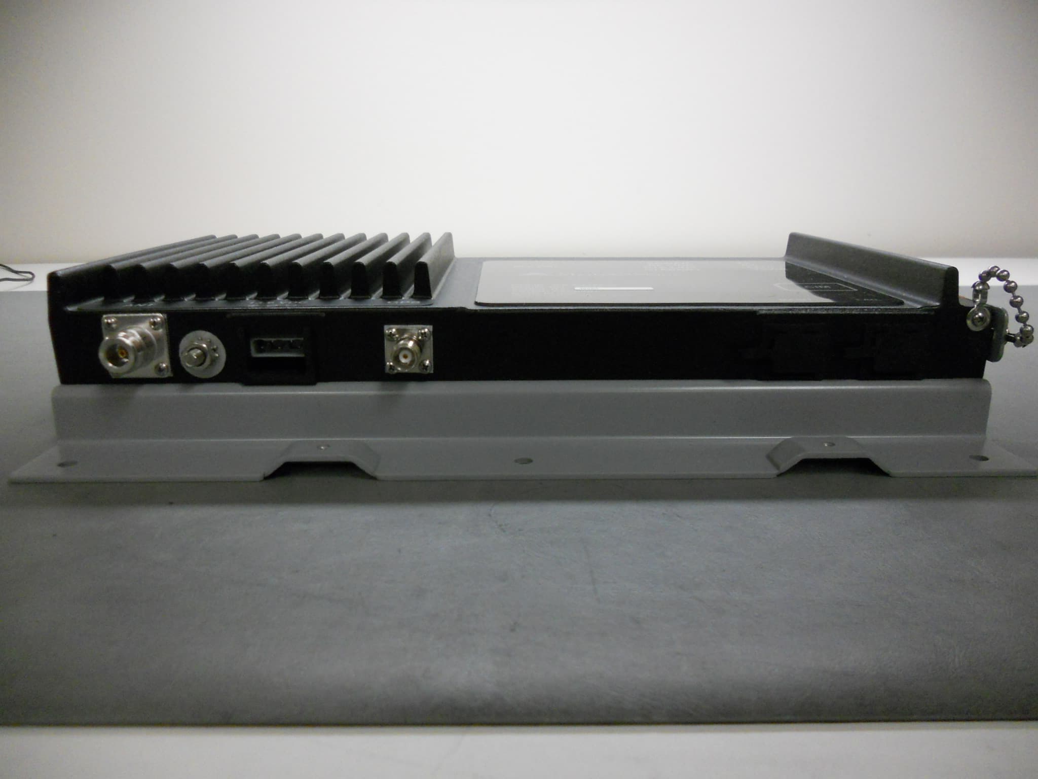
Click to zoom
Application Details
- Equipment Class
- TNB - Licensed Non-Broadcast Station Transmitter
- Date of Grant
- Oct 30, 2011
- Application Purpose
- Original Equipment
- Date of Application
- Oct 30, 2011
- Equipment Note
- Wayside Packet Data Transceiver
- Frequency Range
- 220.01250000 - 221.98750000
- Company
- Meteorcomm LLC
- Country
- United States
Documents & Files
Document Text
Text extracted from the exhibit documents filed with the FCC. Open a document above to read the original.
Users Manual
ITCR Wayside Radio User's Manual and Installation Instructions Applicable Model: 63010 Note: The final version of this manual will include a French translation of the notices to user in Sections 2 and 3. ITCR Wayside Radio User's GuideManual © 2011 Meteorcomm LLC. All Rights Reserved. Proprietary and Confidential ii 10/20/2011 Revision History Revision Date Summary of Changes Contributor 0.1 Initial draft. Jeff Lawrence 0.2 Changes by Jeff Lawrence Jeff Lawrence 0.3 08/29/2011 Added Notices to user, renamed and edited for FCC submission Fred Cleveland 0.4 09/08/2011 Fixed errors and omissions. Fred Cleveland 0.5 10/04/2011 Expanded and edited in response to examiner comments. Fred Cleveland 0.6 10/06/2011 Corrected voltages. Fred Cleveland Tim Blom 0.7 10/20/2011 Revised Section 2.2, 3.3 and 5.4 Fred Cleveland ITCR Wayside Radio User's GuideManual © 2011 Meteorcomm LLC. All Rights Reserved. Proprietary and Confidential 10/20/2011 1 Table of Contents 1. Overview ............................................................................................................................. 3 1.1 Applicable Radio Models and Identifiers ................................................................ 3 1.2 General Description ................................................................................................ 3 1.3 Chassis ..................................................................................................................... 4 1.4 Ports and Ethernet Connectors .............................................................................. 4 1.5 Power Connectors ................................................................................................... 4 1.6 Antenna Connectors ............................................................................................... 4 2. Important Information for the User ................................................................................... 4 2.1 Transmitter Warm‐Up Period. ................................................................................ 4 2.2 Limiting RF Exposure ............................................................................................... 5 2.3 Antenna Guidelines ................................................................................................. 5 2.4 RF Interference to Residential Receivers (Part 15) ................................................. 6 2.5 Equipment Modifications ....................................................................................... 7 3. Wayside Transmitter Operation ......................................................................................... 7 3.1 Wayside Channelization and Frequency Range ...................................................... 7 3.2 Wayside Channel Restrictions ................................................................................ 7 3.3 Wayside Radiated Power Limits ............................................................................. 8 4. Setup and Configuration for the Wayside Radio ................................................................ 9 4.1 Power Supply .......................................................................................................... 9 4.2 Ethernet Connection ............................................................................................. 10 4.3 RF Output Termination ......................................................................................... 10 5. Tuning the Wayside Radio ................................................................................................ 11 5.1 Equipment Required ............................................................................................. 11 5.2 Set up the Radio for Testing.................................................................................. 11 5.3 Measure and Calibrate Reference Crystal Oscillator Frequency .......................... 12 5.4 Measure and Adjust Output Power ...................................................................... 13 5.5 Check and Adjust RF Output Channel ................................................................... 14 6. Operations ........................................................................................................................ 15 6.1 Restore Factory Settings ....................................................................................... 15 ITCR Wayside Radio User's GuideManual © 2011 Meteorcomm LLC. All Rights Reserved. Proprietary and Confidential 2 10/20/2011 6.2 Display Software and Firmware Revision Numbers.............................................. 15 6.3 Display Radio Identification Information .............................................................. 15 ITCR Wayside Radio User's GuideManual © 2011 Meteorcomm LLC. All Rights Reserved. Proprietary and Confidential 10/20/2011 3 1. Overview This document provides information required for the operation and verification of the Meteorcomm Interoperable Train Control Radio Network (ITCR) Wayside radios. 1.1 Applicable Radio Models and Identifiers This document applies to the Wayside radio model listed below along with its regulatory identifiers. Model: 63010 FCC ID: BIB63010 IC: 1300A‐63010 1.2 General Description The Wayside radio is designed to satisfy the industry standard Positive Train Control (PTC) requirements as part of an integrated 220 MHz radio network. The Base radio, Locomotive radio, and Wayside radio form the transportation backbone on which a messaging application provides communication capabilities between railroad assets and their back offices. The ITCR is designed to provide communication in an inter‐ operable fashion enabling messaging to occur across railroad boundaries. When applied as a mobile station, this radio will be mounted in mobile maintenance vehicles such as pickup trucks. It will actively join the ITC network only when maintenance vehicles are driven on the rails. The Wayside radio is normally positio…
Text truncated - open the document above for the full version.
Cover Letter(s)
TÜV SÜD America Inc. Phone: (651) 638-0297 19333 Wild Mountain Road Fax: (651) 638-0298 Taylor Falls, MN 55084 E-mail: [email protected] www.TUVamerica.com Management Service • Product Service • Industry Service TÜV SÜD AMERICA INC 19333 WILD MOUNTAIN ROAD TAYLORS FALLS, MINNESOTA 55084-1786 ENGINEERING STATEMENT For Certification of METEORCOMM LLC Wayside Radio Model No: 63010 FCC ID: BIB63010 FRN: 0021060629 IC: 1300A-63010 I am an Electromagnetic Compatibility Engineer for TÜV SÜD AMERICA INC, Taylors Falls, Minnesota. My education and experience are a matter of record with the Federal Communications Commission. TÜV SÜD AMERICA INC has been authorized by Larry Corvari, Director, Product Development, of METEORCOMM LLC, to make Certification measurements of the above mentioned equipment. I attest that all testing done under my supervision was done in accordance with, and that the EUT fulfills the requirements of, the Federal Communications Commission's CFR 47 Part 90 and Industry Canada's RSS-119 Issue 11. Joel T. Schneider Senior Engineer Minnesota Wild River Lab TÜV SÜD America Product Service Tel: 651 604 4582 Fax: 651 638 0298 [email protected] Dated: 09 September 2011
External Photos
63010 WaysideRadio - External Pictures Front View 63010 WaysideRadio - External Pictures Connector Side View 63010 WaysideRadio - External Pictures Left Side View 63010 WaysideRadio - External Pictures Right Side View 63010 WaysideRadio - External Pictures Top View 63010 WaysideRadio - External Pictures Bottom View 63010 WaysideRadio - External Pictures SD Flash Card View
ID Label/Location Info
MeteorComm Wayside Radio Model: 63010 Label Location
Internal Photos
63010 WaysideRadio - Internal Pictures Chassis Internal View, back cover removed 63010 WaysideRadio - Internal Pictures Chassis Internal View, cables & shields removed 63010 WaysideRadio - Internal Pictures Master Board, Top View 63010 WaysideRadio - Internal Pictures Master Board Bottom View 63010 WaysideRadio - Internal Pictures PA Board, Top View 63010 WaysideRadio - Internal Pictures PA Board, Bottom View 63010 WaysideRadio - Internal Pictures Front-End Board, Top View, RF Coupler cover removed 63010 WaysideRadio - Internal Pictures 63010 WaysideRadio - Internal Pictures Heatsink Chssis 63010 WaysideRadio - Internal Pictures Heatsink Chassis, Exploded View 63010 WaysideRadio - Internal Pictures Wayside Radio, disassembled
RF Exposure Info
MCC PTC Radio RF Energy Exposure Guide 1 v9 10/21/2011 RF Energy Exposure Guide for Meteorcomm PTC Radios Installed in Vehicles or at Fixed Sites IMPORTANT IMPORTANT RF Energy Exposure Awareness and Control Information, and Operational Instructions for FCC/IC Occupational Use Requirements NOTICE: This radio is intended for use in occupational/controlled conditions, where users have full knowledge of their exposure and can exercise control over their exposure to meet FCC/IC limits. This radio device is NOT authorized for general population, consumer, or any other use. This two-way radio uses electromagnetic energy in the radio frequency (RF) spectrum to provide communications between two or more users over a distance. It uses RF energy or radio waves to send and receive messages. RF energy is one form of electromagnetic energy. Other forms include, but are not limited to, sunlight and x-rays. RF energy, however, should not be confused with these other forms of electromagnetic energy, which when used improperly, can cause biological damage. Very high levels of x-rays, for example, can damage tissues and genetic material. Experts in science, engineering, medicine, health, and industry work with organizations to develop standards for safe exposure to RF energy. These standards provide recommended levels of RF exposure for both workers and the general public. These recommended RF exposure levels include substantial margins of protection. All two-way radios marketed in North America are designed, manufactured, and tested to ensure they meet government-established RF exposure levels. In addition, manufacturers also recommend specific operating instructions to users of two-way radios. These instructions are important because they inform users about RF energy exposure and provide simple procedures on how to control it. Please refer to the following Web sites for more information on what RF energy exposure is and how to control your exposure to assure compliance with established RF exposure limits. http://www.fcc.gov/oet/rfsafety/rf-faqs.html BEFORE INSTALLING, MAINTAINING OR USING YOUR RADIO, READ THIS GUIDE WHICH CONTAINS IMPORTANT RF ENERGY AWARENESS AND CONTROL INFORMATION AND OPERATIONAL INSTRUCTIONS TO ENSURE COMPLIANCE WITH FEDERAL COMMUNICATIONS COMMISSION OR INDUSTRY CANADA RF EXPOSURE GUIDELINES. RETAIN THIS GUIDE AT THE LOCATION OF THE RADIO INSTALLATION. MCC PTC Radio RF Energy Exposure Guide 2 v9 10/21/2011 http://www.osha.gov/SLTC/radiofrequencyradiation/index.html FCC/ Industry Canada Regulations The FCC/IC rules require manufacturers to comply with the FCC/IC RF energy exposure limits for mobile two-way radios before they can be marketed in the U.S. or Canada as applicable. When two-way radios are used as a consequence of employment, the FCC/IC requires users to be fully aware of and able to control their exposure to meet occupational requirements. Your MCC user manuals and this RF Energy Exposure Guide include information and operating instructions required to control your RF exposure and to satisfy compliance requirements. Compliance with RF Exposure Standard Your MCC two-way radio is designed and tested to comply with a number of national and international standards and guidelines (listed below) regarding human exposure to radio frequency electromagnetic energy. This radio complies with the IEEE and ICNIRP exposure limits for occupational/controlled RF exposure environment at duty factors as shown in Tables 1 and 2 and is authorized by the FCC/IC for occupational use. In terms of measuring RF energy for compliance with the FCC/IC exposure guidelines, your radio antenna radiates measurable RF energy only while it is transmitting, not when it is receiving or in standby mode. Your MCC two-way radio complies with the following RF energy exposure standards and guidelines as of the date of manufacture: • U. S. Federal Communications Commission, Code of Federal Regulations; 47CFR Part 2 Subpart J • Industry Canada RSS-102 Issue 4. • American National Standards Institute (ANSI) / Institute of Electrical and Electronic Engineers (IEEE) C95. 1-1992 • Institute of Electrical and Electronic Engineers (IEEE) C95.1-1999 Edition MCC PTC Radio RF Energy Exposure Guide 3 v9 10/21/2011 Mobile Installations: RF Exposure Compliance, Control Guidelines and Operating Instructions To control exposure to yourself and others and to ensure compliance with occupational/controlled environment exposure limits, always adhere to the following procedures. 1. Guidelines: These user awareness instructions should accompany the device or vehicle that it is installed in when transferred to other users. Do not use this device if the operational requirements described herein are not met. 2. Operator Instructions: Be aware that a transmitter may operate automatically at any time when functioning as a data radio. People outside of the vehicle must maintain the recommended minimum lateral distance from the antennas at all times. It is the responsibility of the vehicle’s operator to keep bystanders beyond the minimum lateral distance from the antennas in order to comply with the FCC RF exposure limits for an uncontrolled/general population environment. Verify that people outside the vehicle are at least the recommended minimum lateral distance away, as shown in Table 1, from a properly installed externally-mounted antenna. The transmitter power is adjustable to accommodate the various installations of this product. Once the authorized ERP, antenna gain and the losses from feed line, connectors and any inline RF filters are known, the transmitter power must be evaluated and if necessary, set to a value that will ensure that the authorized ERP and RF exposure requirements are met. Refer to the user manual for the particular radio model for additional information regarding power adjustment. Table 1 below lists the recommended lateral distances to be maintained between bystanders and approved, properly installed mo…
Text truncated - open the document above for the full version.
RF Exposure Info
RF Exposure Calculations for ITC Packet Data Transceivers RF Exposure Calculations © 2011 Meteorcomm LLC. All Rights Reserved. Proprietary and Confidential ii 10/21/2011 Revision History Revision Date Summary of Changes Contributor 1 10/5/2011 Original Fred Cleveland Norm Shivley 2 10/6/2011 Clarification edits. Tim Blom 3 10/21/2011 Revise calculations Fred Cleveland Tim Blom RF Exposure Calculations © 2011 Meteorcomm LLC. All Rights Reserved. Proprietary and Confidential 10/21/2011 1 RF Exposure Calculations 1. Determination of Need for Routine Environmental Evaluation for RF Exposure per §2.1091(c) It is the view of Meteorcomm LLC that the ITC Radio models 63010, 63020, 63030-24 and 63030-48 also known respectively as Wayside, Locomotive and Base radios, are not subject to routine environmental evaluation for RF exposure. While these models are intended for use in Part 90 applications, they are not designed for use in the Specialized Mobile Radio Service. 2. RF Exposure Environment Per OET Bulletin 65, there are two environments relevant to RF exposure analysis: Occupational/controlled limits apply in situations in which persons are exposed as a consequence of their employment provided those persons are fully aware of the potential for exposure and can exercise control over their exposure. Limits for occupational/ controlled exposure also apply in situations when an individual is transient through a location where occupational/controlled limits apply provided he or she is made aware of the potential for exposure. General population/uncontrolled exposures apply in situations in which the general public may be exposed, or in which persons that are exposed as a consequence of their employment may not be fully aware of the potential for exposure or cannot exercise control over their exposure. As the Wayside and Locomotive models can be deployed in a mobile/vehicular installation, it is possible for both environments to apply. The radio operator may be considered to be in an occupational/controlled exposure environment if she or he is properly trained to be aware of exposures and to control emissions. Vehicle passengers and bystanders are generally considered to be in a general population/uncontrolled exposure environment. This being the case, vehicular antenna installation must take into account both environments, or, at the least, the RF Exposure Calculations © 2011 Meteorcomm LLC. All Rights Reserved. Proprietary and Confidential 2 10/21/2011 more restrictive requirement, that being the general population/uncontrolled environment. The occupational/controlled exposure limits generally apply to base station applications. 3. RF Exposure Limit Calculations Per Table 1 of OET Bulletin 65, Appendix A, the FCC limits for Maximum Permitted Exposure (MPE) in terms of power density, S, are shown below. For an Occupational/Controlled Exposure environment: S = 1.0mW/cm 2 for the frequency range of 30-300 MHz, For a General Population/Uncontrolled Exposure environment: S = 0.2mW/cm 2 for the frequency range of 30-300 MHz, The minimum separation required between a human and an antenna connected to an active antenna can be determined by use of the power density expression: R PG S 4 Where S = power density in mW/cm 2 P = Average RF power into the antenna in mW G = antenna gain - isotropic (unitless, linear) R = separation/distance between antenna and point of interest in cm Solved for R, the formula becomes: S PG R 4 RF Exposure Calculations © 2011 Meteorcomm LLC. All Rights Reserved. Proprietary and Confidential 10/21/2011 3 Note that the π/4DQPSK modulation emitted by all ITC radio transceivers has amplitude components created by the 0.35 excess bandwidth root raised cosine pre- modulation low pass filter. The peak to average power ratio is known to be 3.0 or more dB. The peak envelope power of the transmitters is converted to average power by applying a 3 dB conversion factor in the calculations below. The charts below show the maximum transmit power levels converted to average, duty cycles, maximum power densities and R, the calculated minimum human separation for each band. Several example antenna types are shown. Antenna gains shown are relative to an isotropic radiator. The gain relative to a dipole (dBd) is 2.15 dB less in each case. Example calculation for first entry in table of Section 4 below: Maximum conducted power condition Rated power = P rated = 30 W PEP. Measured power = P meas = 30.55 W PEP. Apply the 3 dB peak to average power ratio conversion Average power = P ave = 30.55W/(10^(3/10)) = 30.55W/2.0 = 15.28W. Average power reduced to 10% duty ratio, P = 0.1*15.28 = 1.53 W = 1530 mW. Gain factor for 2.15 dBi is 10^(2.15/10) = 1.64 S = 0.2 mW/cm2 (uncontrolled) R = ((1530*1.64)/(4*3.14159*0.2))^0.5 = 31.6 cm. Radiated power calculation. Antenna gain in dBd = 2.15 dBi – 2.15 dBi to dBd conversion = 0 dBd = 1 numeric P radiated = P meas *Antenna Gain (numeric dBd) = 30.55W*1.00 = 30.55 Watts PEP-ERP RF Exposure Calculations © 2011 Meteorcomm LLC. All Rights Reserved. Proprietary and Confidential 4 10/21/2011 Example calculation for second entry in table of Section 4 below: Set power level = P set = 28.77 W PEP. Apply the 3 dB peak to average power ratio conversion: Average power = 28.77W/(10^(3/10)) = 28.77W/2.0 = 14.39W. Average power reduced to 10% duty ratio, P = 0.1*14.39 = 1.439 W = 1439 mW. Gain factor for 4.55 dBi is 10^(4.55/10) = 2.851 S = 0.2 mW/cm2 (uncontrolled) R = ((1439*2.851)/(4*3.14159*0.2))^0.5 = 40.40 cm. Radiated power calculation. Antenna gain in dBd = 4.55 dBi – 2.15 dBi to dBd conversion = 2.40 dBd = 1.7378 numeric P radiated = P set * gain factor (numeric dBd value) = 28.77W * 1.7378 = 50 watts PEP- ERP Note: When the radiated power is adjusted to the maximum allowed ERP of 50 Watts PEP for the wayside and locomotive, calculated MPE distance for uncontrolled population exposure is always 40.4 cm. The following tables are included in our RF Energy Exposure Gu…
Text truncated - open the document above for the full version.
Test Report
FCC Part 90 / IC RSS-119 06 October 2011 TÜV SÜD AMERICA INC19333 Wild Mountain Road Taylors Falls MN USA 55084-1786 Tel: 651 638 0297 Fax: 651 638 0298 TEST REPORT FCC Part 90 FCC Part 15 Subpart B Industry Canada RSS-119, Issue 11 RSS-Gen, Issue 3 MANUFACTURER Meteorcomm LLC 1201 SW 7 th Street Renton WA 98057 MODEL NUMBER(S) 63010 EUT DESCRIPTION Wayside Radio SERIAL NUMBER(S) TESTED 40063 TEST REPORT NUMBER WC1104224.1B Rev C TÜV SÜD America Inc, as an independent testing laboratory, declares that the equipment tested as specified above conforms to the applicable requirements of FCC Part 90, FCC Part 15 Subpart B, and RSS-119, Issue 11 – “Land Mobile and Fixed Radio Transmitters and Receivers Operating in the Frequency Range 27.41-960 MHz”, and RSS- Gen, Issue 3 – “General Requirements and Information for the Certification of Radio Apparatus.” TÜV SÜD America, Inc and its professional staff hold government and professional organization certifications and are members of AAMI, ACIL, AEA, ANSI, IEEE, NARTE, and VCCI. Not Transferable Test Report WC1104224.1B Rev C1 of 86 FCC Part 90 / IC RSS-119 06 October 2011 TÜV SÜD AMERICA INC19333 Wild Mountain Road Taylors Falls MN USA 55084-1786 Tel: 651 638 0297 Fax: 651 638 0298 1.0 TEST RESULT SUMMARY Tables 1 and 2 summarize the results for the tested EUT with respect to the essential requirements defined in FCC Parts 90, 15 and RSS-119, Issue 11 and RSS-Gen, Issue 3. 1.1. Transmitter Table 1: Transmitter results summary FCC Section Test Measured Limit Result §2.1033(c)(5) §90.35, §90.715 Frequency ranges 217-220 MHz – N/A 220-222 MHz Complies §2.1033(c)(6), (7) §2.1046, §90.205 §90.723, §90.729 Power 2 W 217-220 MHz – N/A 500 W 220-221 MHz 50 W 221-222 MHz Complies §2.1033(c)(4) §2.1047, §90.210 Emission types Information only §2.1033(c)(4) §2.1047, §90.210, 90.733(e) Emission mask F – 220-222 MHz B – 217-220 MHz – N/A Complies §2.1049, §90.209 §90.259, 90.733(d) Bandwidth 50/25/12.5/6.25 kHz – 217-220 MHz – N/A 4 kHz – 220-222 MHz 4 Complies §2.1051, §2.1057 §90.210 Spurious emissions Case radiation Mask B - -13 dBm – N/A Mask F - -25 dBm Complies §2.1055, §90.213 Frequency stability 1 ppm – 217-220 MHz – N/A 1.5 ppm – 220-222 MHz Complies §15.109 Receiver emissions Complies RSS-119 Clause Test Measured Limit Result RSS-119 Frequency ranges 217-220 MHz – N/A 220-222 MHz 1 Complies 5.4.4 SRSP-512 Power 5 W 217-218 MHz – N/A 5 W 219-220 MHz – N/A 125 W 220-221 MHz 2 50 W 221-222 MHz Complies 5.5 Table 3 Emission mask D or J – 217-218 MHz 3 – N/A D or J – 219-220 MHz 3 – N/A F – 220-222 MHz Complies 5.5 Table 3 Emission types Information only 5.5 Table 3 Bandwidth 11.25 kHz – 217-218 MHz – N/A 11.25 kHz – 219-220 MHz – N/A 4 kHz – 220-222 MHz Complies 5.8 Spurious emissions Mask D/J - -20 dBm – N/A Mask F - -25 dBm Complies 5.3 Frequency stability 5 ppm – 217-218 MHz – N/A 5 ppm – 219-220 MHz – N/A 1.5 ppm – 220-222 MHz Complies RSS-Gen Issue 3 Receiver emissions Complies 1 RSS-119 limits operation to 217-218 MHz and 219-222 MHz. 2 See SRSP-512 3 D or I if device has audio filter 4 Licensees, except for licensees authorized on Channels 161 through 170 and 181 through 185, may combine any number of their authorized, contiguous channels (including channels derived from multiple authorizations) to form channels wider than 5 kHz. NOTE: Antenna gain = per license. Test Report WC1104224.1B Rev C2 of 86 FCC Part 90 / IC RSS-119 06 October 2011 TÜV SÜD AMERICA INC19333 Wild Mountain Road Taylors Falls MN USA 55084-1786 Tel: 651 638 0297 Fax: 651 638 0298 REVISION RECORD REVISION TOTAL NUMBER OF PAGES DATE DESCRIPTION 84 12 July 2011 Initial Release A 84 12 September 2011 Corrected frequency stability limit. B 84 05 October 2011 Added traceability statement. C 86 06 October 2011 Page 2 - FCC power section from 90.259 to 90.723, allowed power from 250 W to 500 W, added 90.733(e) to emission mask requirements, frequency stability from 0.1 ppm to 1.5 ppm Page 10 – 220-221 MHz limit to fixed, 220-221 MHz limit to mobile, 221-222 MHz limit to fixed and mobile Page 15 – limit to 90.210(f), 90.733(e); RSS-119 5.5, 5.6 and SRSP-512 4.1.5 Inserted pp. 16-17 Test Report WC1104224.1B Rev C3 of 86 FCC Part 90 / IC RSS-119 06 October 2011 TÜV SÜD AMERICA INC19333 Wild Mountain Road Taylors Falls MN USA 55084-1786 Tel: 651 638 0297 Fax: 651 638 0298 List of contents Page 1. Test result summary 2 2. Introduction 5 3. Testing laboratory 5 4. Applicant 6 5. Product and product documentation 6 6. Conclusions, observations and comments 7 7. Environmental conditions in the lab 8 8. Transmitter parameters 9 8.1 Frequency ranges 9 8.2 Power 9 - 14 8.3 Emission mask 15 - 18 8.4 Bandwidth 19 - 20 8.5 Spurious emissions 21 - 54 8.6 Frequency stability 55 - 57 8.7 Receiver emissions 58 - 72 9. Photographs of the EUT test setup 73 - 78 10. EUT information 79- 86 Test Report WC1104224.1B Rev C4 of 86 FCC Part 90 / IC RSS-119 06 October 2011 TÜV SÜD AMERICA INC19333 Wild Mountain Road Taylors Falls MN USA 55084-1786 Tel: 651 638 0297 Fax: 651 638 0298 2. Introduction This testing is intended to verify the Meteorcomm Wayside Radio is performing in accordance with the requirements of FCC Part 90, RSS-Gen and RSS-119. This test report consists of: Test result summary List of contents Introduction and further information Equipment application data Detailed test information List of measurement equipment with calibration validity Photographs and further test results (plots, graphs, etc.) All pages have been numbered consecutively and bear TÜV SÜD America, the test report number, the date, the test specification in its current version as well as the type designation of the EUT. The total number of pages in this report is 84. The tests were carried out on a representative assembly and in accordance with the test methods stated in: ANSI C63.4-2003; ANSI TIA-603-C, 2004. The sample(s) of the product was received on: 09 May 2011 The tests were carried out in the following perio…
Text truncated - open the document above for the full version.
Test Report
FCC Part 90 / IC RSS-119 06 October 2011 TÜV SÜD AMERICA INC19333 Wild Mountain Road Taylors Falls MN USA 55084-1786 Tel: 651 638 0297 Fax: 651 638 0298 FCC Conducted Emissions below 1 GHz Tx port Transmit mode 30 watt peak power Modulation: DQPSK_HALF High channel: 221.9875 MHz Close in emissions Test Report WC1104224.1B Rev C44 of 86 FCC Part 90 / IC RSS-119 06 October 2011 TÜV SÜD AMERICA INC19333 Wild Mountain Road Taylors Falls MN USA 55084-1786 Tel: 651 638 0297 Fax: 651 638 0298 FCC Conducted Emissions below 1 GHz Tx port Transmit mode 7.5 watt peak power Modulation: DQPSK_HALF Low channel: 220.0125 MHz Spectrum Analyzer = EXA Test Report WC1104224.1B Rev C45 of 86 FCC Part 90 / IC RSS-119 06 October 2011 TÜV SÜD AMERICA INC19333 Wild Mountain Road Taylors Falls MN USA 55084-1786 Tel: 651 638 0297 Fax: 651 638 0298 FCC Conducted Emissions below 1 GHz Tx port Transmit mode 7.5 watt peak power Modulation: DQPSK_HALF High channel: 221.9875 MHz Spectrum Analyzer = EXA Test Report WC1104224.1B Rev C46 of 86 FCC Part 90 / IC RSS-119 06 October 2011 TÜV SÜD AMERICA INC19333 Wild Mountain Road Taylors Falls MN USA 55084-1786 Tel: 651 638 0297 Fax: 651 638 0298 FCC Conducted Emissions below 1 GHz Tx port Transmit mode 7.5 watt peak power Modulation: DQPSK_HALF Low channel: 220.0125 MHz Spectrum Analyzer = EXA Test Report WC1104224.1B Rev C47 of 86 FCC Part 90 / IC RSS-119 06 October 2011 TÜV SÜD AMERICA INC19333 Wild Mountain Road Taylors Falls MN USA 55084-1786 Tel: 651 638 0297 Fax: 651 638 0298 FCC Conducted Emissions below 1 GHz Tx port Transmit mode 7.5 watt peak power Modulation: DQPSK_HALF Low channel: 220.0125 MHz Close in emissions Spectrum Analyzer = EXA Test Report WC1104224.1B Rev C48 of 86 FCC Part 90 / IC RSS-119 06 October 2011 TÜV SÜD AMERICA INC19333 Wild Mountain Road Taylors Falls MN USA 55084-1786 Tel: 651 638 0297 Fax: 651 638 0298 FCC Conducted Emissions below 1 GHz Tx port Transmit mode 7.5 watt peak power Modulation: DQPSK_HALF High channel: 221.9875 MHz Spectrum Analyzer = EXA Test Report WC1104224.1B Rev C49 of 86 FCC Part 90 / IC RSS-119 06 October 2011 TÜV SÜD AMERICA INC19333 Wild Mountain Road Taylors Falls MN USA 55084-1786 Tel: 651 638 0297 Fax: 651 638 0298 FCC Conducted Emissions below 1 GHz Tx port Transmit mode 7.5 watt peak power Modulation: DQPSK_HALF High channel: 221.9875 MHz Close in emissions Spectrum Analyzer = EXA Test Report WC1104224.1B Rev C50 of 86 FCC Part 90 / IC RSS-119 06 October 2011 TÜV SÜD AMERICA INC19333 Wild Mountain Road Taylors Falls MN USA 55084-1786 Tel: 651 638 0297 Fax: 651 638 0298 FCC / Industry Canada Conducted Emissions above 1 GHz Tx port Transmit mode 30 watt peak power Modulation: DQPSK_HALF Low channel: 220.0125 MHz Test Report WC1104224.1B Rev C51 of 86 FCC Part 90 / IC RSS-119 06 October 2011 TÜV SÜD AMERICA INC19333 Wild Mountain Road Taylors Falls MN USA 55084-1786 Tel: 651 638 0297 Fax: 651 638 0298 FCC / Industry Canada Conducted Emissions above 1 GHz Tx port Transmit mode 30 watt peak power Modulation: DQPSK_HALF High channel: 221.9875 MHz Test Report WC1104224.1B Rev C52 of 86 FCC Part 90 / IC RSS-119 06 October 2011 TÜV SÜD AMERICA INC19333 Wild Mountain Road Taylors Falls MN USA 55084-1786 Tel: 651 638 0297 Fax: 651 638 0298 FCC / Industry Canada Conducted Emissions above 1 GHz Tx port Transmit mode 7.5 watt peak power Modulation: DQPSK_HALF Low channel: 220.0125 MHz Spectrum Analyzer = EXA Test Report WC1104224.1B Rev C53 of 86 FCC Part 90 / IC RSS-119 06 October 2011 TÜV SÜD AMERICA INC19333 Wild Mountain Road Taylors Falls MN USA 55084-1786 Tel: 651 638 0297 Fax: 651 638 0298 FCC / Industry Canada C…
Text truncated - open the document above for the full version.
Contact Information
Applicant
Dave Herber(VP Engineering)
Technical Contact
TUV SUD America Inc.Joel T Schneider
[email protected]651 638 0297
19333 Wild Mountain Road · Taylors Falls, Minnesota · United States
Non-Technical Contact
TUV SUD America Inc.Susan L Rupp
[email protected]651 604 4585
Test Firm
TUV SUD America, Inc.Stephen Lee
Technical Specifications
| # | Rule Parts | Frequency Range | Power Output | Emission | Tolerance |
|---|---|---|---|---|---|
| 2 | 9 | 220.0125 MHz - 221.9875 MHz | 7.53 W | 8K90DXW | 1.5 ppm |
Other Applications from Meteorcomm LLC

BIB54505003-01
Feb 23, 2012Packet Data Radio Transceiver - Fixed or Mobile
Equipment Class
TNB - Licensed Non-Broadcast Station Transmitter
BIB63020
Nov 10, 2011Locomotive Radio
Equipment Class
TNB - Licensed Non-Broadcast Station Transmitter
BIB63030-24
Oct 03, 2011Packet Data Transceiver - Fixed Use - 24VDC
Equipment Class
TNB - Licensed Non-Broadcast Station Transmitter
BIB63030-48
Sep 22, 2011Packet Data Transceiver - Fixed Use - 48VDC
Equipment Class
TNB - Licensed Non-Broadcast Station Transmitter
BIB61201001
Mar 27, 2007Land Mobile Packet Data Transceiver
Equipment Class
TNB - Licensed Non-Broadcast Station Transmitter