BIB54530001REMOTE EMERGENCY DEVICE
Meteorcomm LLC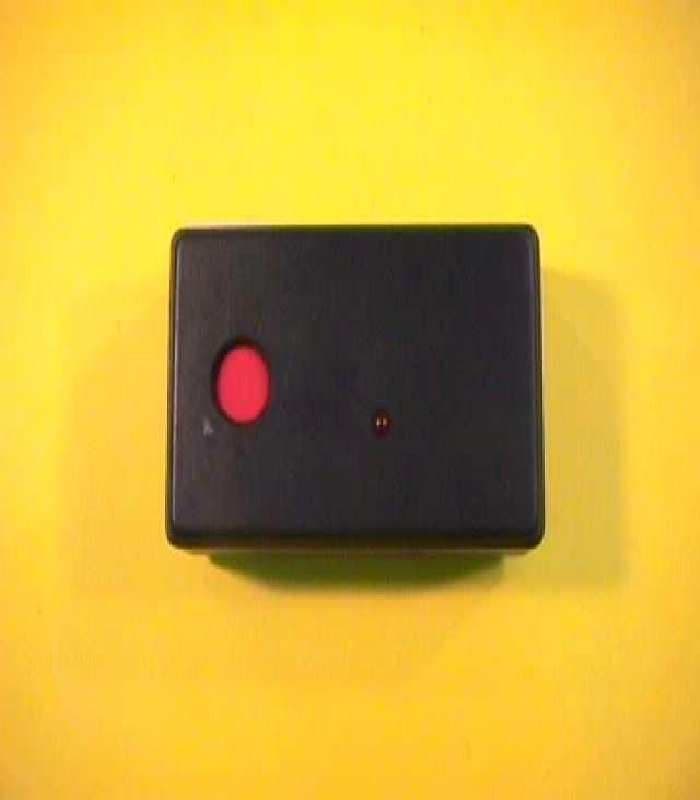
Click to zoom
Application Details
- Equipment Class
- TNT - Licensed Non-Broadcast Transmitter Worn on Body
- Date of Grant
- Apr 04, 1999
- Application Purpose
- Original Equipment
- Date of Application
- Jan 25, 1999
- Equipment Note
- REMOTE EMERGENCY DEVICE
- Frequency Range
- 36.00000000 - 50.00000000
- Company
- Meteorcomm LLC
- Country
- United States
Documents & Files
Document Text
Text extracted from the exhibit documents filed with the FCC. Open a document above to read the original.
Users Manual
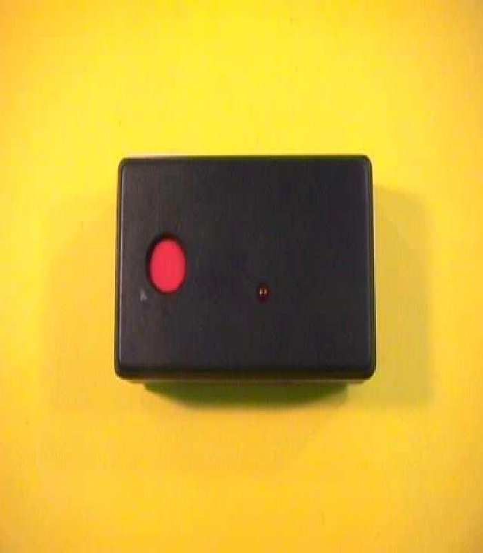
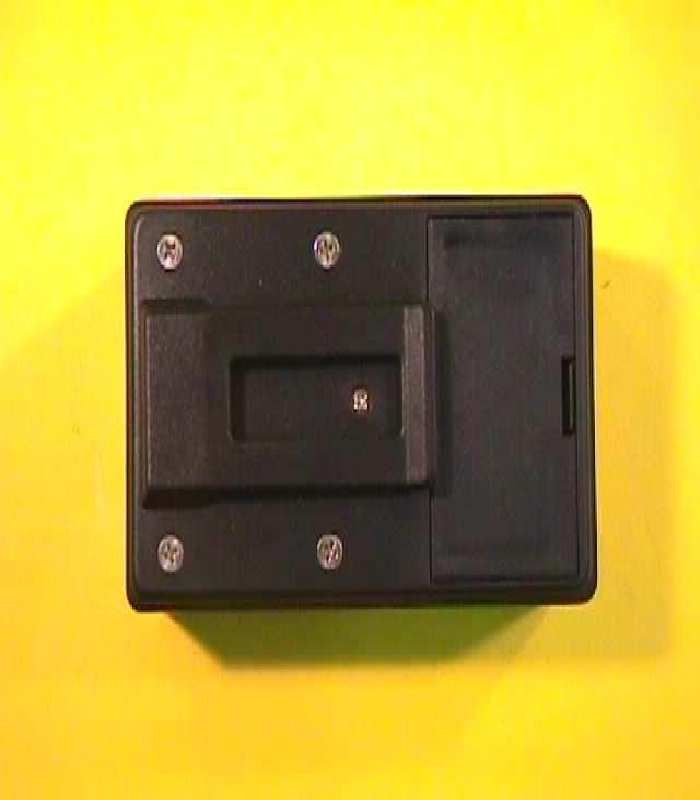
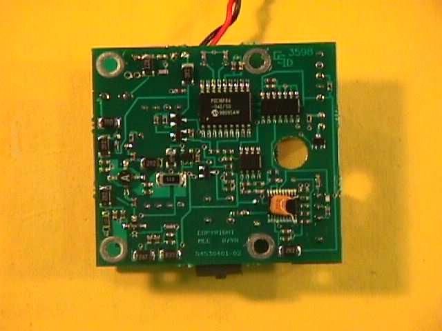
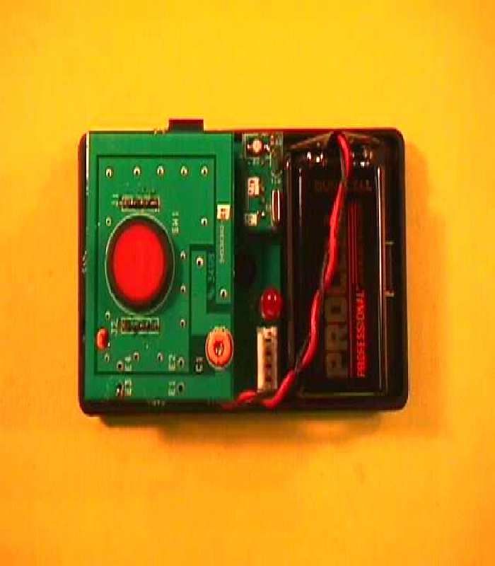
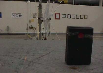
FCC TYPE ACCEPTANCE DOCUMENTATION FOR THE MCC-54530001 REMOTE EMERGENCY DEVICE (RED) December 15, 1998 METEOR COMMUNICATIONS CORPORATION 8631 South 212 th Street Kent, WA. 98031 Tel: 253-872-2521Fax: 253-872-7662 © 1998 by Meteor Communications Corporation all rights reserved 2 TABLE OF CONTENTS INTRODUCTION3 DESCRIPTION3 SPECIFICATIONS3 OPERATION4 THEORY OF OPERATION5 Block Diagram5 Power Switch and Battery Status Indicator6 5 Volt Regulator6 Microcontroller6 Differential Data Encoder6 Data Filter6 Transmit Crystal Oscillator6 Phase Modulator6 RF Power Amplifier7 Harmonic Filter7 Loop Antenna7 TEST PROCEDURE8 APPENDIX A10 Drawings APPENDIX B14 Test Results Form APPENDIX C15 Final Assembly Pictures APPENDIX D16 Printed Circuit Assembly Pictures APPENDIX E17 FCC Identification Label Source Control Drawing 3 INTRODUCTION The Meteor Communications Corporation (MCC) Remote Emergency Device (RED) is a low power, RF transmitter, designed for use with the MCC-545A RF Modem. The unit was developed as a personal emergency-signaling device that provides short-range connectivity between the user and a nearby 545A. DESCRIPTION The RED is a battery operated, handheld device with a minimum operational range of 1,500 feet. In an emergency, the operator presses the red button on the unit to transmit an alert message. There is also a test button and battery indicator to periodically determine the functional status of the unit. When not in use, the unit can be clipped to the user's belt. SPECIFICATIONS Transmitter Frequency Range36-50MHz Frequency Stability+/- 20ppm (-30 to +60 o C) Transmit Power250mW (at 9VDC) Rated Emission16KOG1WWN Spurious and Harmonic Emissions-37dBc ModulationBPSK Data Rate4k bps Transmit Data Sequence Duration300ms Antenna Gain-36 dBd Power Requirements Voltage9VDC Transmit Current250mA Battery Life (Alkaline) Continuous Transmit2 hours Standby5 years Dimensions4.0"L x 2.4"W x 1.4"H Weight5 ounces 4 OPERATION Battery The RED requires a 9-volt alkaline battery to operate. It is installed through an access panel on the back of the unit. A light on the front of the unit provides a visual indication of the battery's status whenever the test button is pressed. It will light as long as the battery voltage is greater than 8VDC. Message Transmission The RED will transmit two types of messages to the 545A, alert or test. Both messages are automatically sent 10 times with each button push for redundancy. In the event of an emergency, press the large, red button on the front of the unit to send an alert message. To test unit functionality, press the small, black button on the side of the unit to send a test message. To ensure message transmission, the buttons must be held down at least 100ms. When the button is released, the unit will complete its transmission cycle and then power down. If the button is held down, the unit will transmit message sequences continuously. Range The operational range of the RED is affected by its distance from the receiver, the type of terrain in between, and the noise floor at the receiver. The RED is specified at 1,500 feet over level terrain, with a noise floor off 0.1uV at the 545A. Any deviation from these conditions will produce variations in the operational range of the unit accordingly. 5 THEORY OF OPERATION The MCC RED is a low-power (250mW) radio transmitter designed for one-way data communications in the low VHF band (36-50 MHz). Information is transmitted in Binary Phase Shift Key (BPSK) form, using a monolithic quadrature modulator. See Appendix A for assembly and schematic drawings. Block Diagram LOOP AN TENN A TR ANSMIT CRYSTAL OSCI LLATO R PHA SE MOD U LATO R RF POWE R AMPLIFIE R H ARMONIC FILTER P ROG RAMMING I /O DATA FILTER 4. 096MH Z CRYSTAL DIFFERENTIAL DATA EN CODER MI CROC ONTR OLLER 9 VOLTS 5 VOL TS V OLTAG E REGU LATOR 9 VO LT B ATTER Y POW ER S WITC H BATTERY STATU S IND ICATOR ALE RT SWITCH TE ST SWITCH 6 Power Switch and Battery Status Indicator Whenever switch SW1 or S2 is pressed, components Q1, Q2, CR1, R2, R3, R5, and R6 switch battery power to all the circuits, except for the final power amplifier stage, which is always connected. The circuits include the 5-volt regulator, and the first and second stages of the power amplifier circuit. Whenever S2 is pressed, power is also routed to the light emitting diode CR2, through components CR3, and R24 as a visual indication of the battery status. The indicator will not light when the battery voltage is below 8 volts. 5 Volt Regulator A linear voltage regulator (U1) provides 5 volts to the microcontroller, differential data encoder, data filter, crystal oscillator, and modulator circuits. Microcontroller An 8-bit, CMOS microcontroller (U3) is used to generate the binary data sequence for transmission. It outputs the appropriate sequence whenever switch SW1 or S2 is pressed. A 4.096MHz crystal (Y2) along with capacitors C15 and C16 determine the operating frequency of the device. The microcontroller also stores the application code and user identification information in internal flash and E 2 PROM memory respectively. Differential Data Encoder A CMOS J-K flip-flop (U6A) is used to differentially encode the binary date prior to entering the data filter. Data Filter An Op-Amp (U5A) based circuit is used to filter the encoded binary data. Capacitors C10, and C13, and resistors R9, R10, and R11 form a second order, low-pass filter with a cut-off frequency of 2 kHz. Resistor R21 reduces the amount of crossover distortion from U5. R15 scales the input to the filter from 0-5VDC to 0-3.2VDC. Transmit Crystal Oscillator A temperature compensated crystal oscillator (Y1) is used to generate the transmitter carrier signal. A trimmer capacitor located on the oscillator allows for fine frequency adjustment of approximately +/- 200Hz. The oscillator's frequency stability is better than +/- 20ppm over a temperature range of –30 o C to +60 o C. Phase Modulator A monolithic quadrature modulator (U4) is used …
Text truncated - open the document above for the full version.
Block Diagram
FCC TYPE ACCEPTANCE DOCUMENTATION FOR THE MCC-54530001 REMOTE EMERGENCY DEVICE (RED) December 15, 1998 METEOR COMMUNICATIONS CORPORATION 8631 South 212 th Street Kent, WA. 98031 Tel: 253-872-2521Fax: 253-872-7662 © 1998 by Meteor Communications Corporation all rights reserved 2 TABLE OF CONTENTS INTRODUCTION3 DESCRIPTION3 SPECIFICATIONS3 OPERATION4 THEORY OF OPERATION5 Block Diagram5 Power Switch and Battery Status Indicator6 5 Volt Regulator6 Microcontroller6 Differential Data Encoder6 Data Filter6 Transmit Crystal Oscillator6 Phase Modulator6 RF Power Amplifier7 Harmonic Filter7 Loop Antenna7 TEST PROCEDURE8 APPENDIX A10 Drawings APPENDIX B14 Test Results Form APPENDIX C15 Final Assembly Pictures APPENDIX D16 Printed Circuit Assembly Pictures APPENDIX E17 FCC Identification Label Source Control Drawing 3 INTRODUCTION The Meteor Communications Corporation (MCC) Remote Emergency Device (RED) is a low power, RF transmitter, designed for use with the MCC-545A RF Modem. The unit was developed as a personal emergency-signaling device that provides short-range connectivity between the user and a nearby 545A. DESCRIPTION The RED is a battery operated, handheld device with a minimum operational range of 1,500 feet. In an emergency, the operator presses the red button on the unit to transmit an alert message. There is also a test button and battery indicator to periodically determine the functional status of the unit. When not in use, the unit can be clipped to the user's belt. SPECIFICATIONS Transmitter Frequency Range36-50MHz Frequency Stability+/- 20ppm (-30 to +60 o C) Transmit Power250mW (at 9VDC) Rated Emission16KOG1WWN Spurious and Harmonic Emissions-37dBc ModulationBPSK Data Rate4k bps Transmit Data Sequence Duration300ms Antenna Gain-36 dBd Power Requirements Voltage9VDC Transmit Current250mA Battery Life (Alkaline) Continuous Transmit2 hours Standby5 years Dimensions4.0"L x 2.4"W x 1.4"H Weight5 ounces 4 OPERATION Battery The RED requires a 9-volt alkaline battery to operate. It is installed through an access panel on the back of the unit. A light on the front of the unit provides a visual indication of the battery's status whenever the test button is pressed. It will light as long as the battery voltage is greater than 8VDC. Message Transmission The RED will transmit two types of messages to the 545A, alert or test. Both messages are automatically sent 10 times with each button push for redundancy. In the event of an emergency, press the large, red button on the front of the unit to send an alert message. To test unit functionality, press the small, black button on the side of the unit to send a test message. To ensure message transmission, the buttons must be held down at least 100ms. When the button is released, the unit will complete its transmission cycle and then power down. If the button is held down, the unit will transmit message sequences continuously. Range The operational range of the RED is affected by its distance from the receiver, the type of terrain in between, and the noise floor at the receiver. The RED is specified at 1,500 feet over level terrain, with a noise floor off 0.1uV at the 545A. Any deviation from these conditions will produce variations in the operational range of the unit accordingly. 5 THEORY OF OPERATION The MCC RED is a low-power (250mW) radio transmitter designed for one-way data communications in the low VHF band (36-50 MHz). Information is transmitted in Binary Phase Shift Key (BPSK) form, using a monolithic quadrature modulator. See Appendix A for assembly and schematic drawings. Block Diagram LOOP AN TENN A TR ANSMIT CRYSTAL OSCI LLATO R PHA SE MOD U LATO R RF POWE R AMPLIFIE R H ARMONIC FILTER P ROG RAMMING I /O DATA FILTER 4. 096MH Z CRYSTAL DIFFERENTIAL DATA EN CODER MI CROC ONTR OLLER 9 VOLTS 5 VOL TS V OLTAG E REGU LATOR 9 VO LT B ATTER Y POW ER S WITC H BATTERY STATU S IND ICATOR ALE RT SWITCH TE ST SWITCH 6 Power Switch and Battery Status Indicator Whenever switch SW1 or S2 is pressed, components Q1, Q2, CR1, R2, R3, R5, and R6 switch battery power to all the circuits, except for the final power amplifier stage, which is always connected. The circuits include the 5-volt regulator, and the first and second stages of the power amplifier circuit. Whenever S2 is pressed, power is also routed to the light emitting diode CR2, through components CR3, and R24 as a visual indication of the battery status. The indicator will not light when the battery voltage is below 8 volts. 5 Volt Regulator A linear voltage regulator (U1) provides 5 volts to the microcontroller, differential data encoder, data filter, crystal oscillator, and modulator circuits. Microcontroller An 8-bit, CMOS microcontroller (U3) is used to generate the binary data sequence for transmission. It outputs the appropriate sequence whenever switch SW1 or S2 is pressed. A 4.096MHz crystal (Y2) along with capacitors C15 and C16 determine the operating frequency of the device. The microcontroller also stores the application code and user identification information in internal flash and E 2 PROM memory respectively. Differential Data Encoder A CMOS J-K flip-flop (U6A) is used to differentially encode the binary date prior to entering the data filter. Data Filter An Op-Amp (U5A) based circuit is used to filter the encoded binary data. Capacitors C10, and C13, and resistors R9, R10, and R11 form a second order, low-pass filter with a cut-off frequency of 2 kHz. Resistor R21 reduces the amount of crossover distortion from U5. R15 scales the input to the filter from 0-5VDC to 0-3.2VDC. Transmit Crystal Oscillator A temperature compensated crystal oscillator (Y1) is used to generate the transmitter carrier signal. A trimmer capacitor located on the oscillator allows for fine frequency adjustment of approximately +/- 200Hz. The oscillator's frequency stability is better than +/- 20ppm over a temperature range of –30 o C to +60 o C. Phase Modulator A monolithic quadrature modulator (U4) is used …
Text truncated - open the document above for the full version.
Cover Letter(s)
December 17, 1998 Federal Communications Commission Authorization and Evaluation Division Laboratory Division 7435 Oakland Mills Road Columbia, MD 21046 Sir/Madam: We the undersigned, hereby authorize Intertek Testing Services to act on our behalf in all matters relating to applications for equipment authorization, including the signing of all documents related to these matters. Any and all acts carried out by Intertek Testing Services on our behalf shall have the same effect as acts of our own. We also hereby certify that no party to the applications authorized hereunder is subject to a denial of benefits, that includes FCC benefits, pursuant to Section 5301 of the Anti-Drug Abuse Act of 1988, 21 U.S.C. 853(a). This agreement expires one year from the current date. Sincerely yours, Tom Donich Vice-President, Engineering
ID Label/Location Info
FCC TYPE ACCEPTANCE DOCUMENTATION FOR THE MCC-54530001 REMOTE EMERGENCY DEVICE (RED) December 15, 1998 METEOR COMMUNICATIONS CORPORATION 8631 South 212 th Street Kent, WA. 98031 Tel: 253-872-2521Fax: 253-872-7662 © 1998 by Meteor Communications Corporation all rights reserved 2 TABLE OF CONTENTS INTRODUCTION3 DESCRIPTION3 SPECIFICATIONS3 OPERATION4 THEORY OF OPERATION5 Block Diagram5 Power Switch and Battery Status Indicator6 5 Volt Regulator6 Microcontroller6 Differential Data Encoder6 Data Filter6 Transmit Crystal Oscillator6 Phase Modulator6 RF Power Amplifier7 Harmonic Filter7 Loop Antenna7 TEST PROCEDURE8 APPENDIX A10 Drawings APPENDIX B14 Test Results Form APPENDIX C15 Final Assembly Pictures APPENDIX D16 Printed Circuit Assembly Pictures APPENDIX E17 FCC Identification Label Source Control Drawing 3 INTRODUCTION The Meteor Communications Corporation (MCC) Remote Emergency Device (RED) is a low power, RF transmitter, designed for use with the MCC-545A RF Modem. The unit was developed as a personal emergency-signaling device that provides short-range connectivity between the user and a nearby 545A. DESCRIPTION The RED is a battery operated, handheld device with a minimum operational range of 1,500 feet. In an emergency, the operator presses the red button on the unit to transmit an alert message. There is also a test button and battery indicator to periodically determine the functional status of the unit. When not in use, the unit can be clipped to the user's belt. SPECIFICATIONS Transmitter Frequency Range36-50MHz Frequency Stability+/- 20ppm (-30 to +60 o C) Transmit Power250mW (at 9VDC) Rated Emission16KOG1WWN Spurious and Harmonic Emissions-37dBc ModulationBPSK Data Rate4k bps Transmit Data Sequence Duration300ms Antenna Gain-36 dBd Power Requirements Voltage9VDC Transmit Current250mA Battery Life (Alkaline) Continuous Transmit2 hours Standby5 years Dimensions4.0"L x 2.4"W x 1.4"H Weight5 ounces 4 OPERATION Battery The RED requires a 9-volt alkaline battery to operate. It is installed through an access panel on the back of the unit. A light on the front of the unit provides a visual indication of the battery's status whenever the test button is pressed. It will light as long as the battery voltage is greater than 8VDC. Message Transmission The RED will transmit two types of messages to the 545A, alert or test. Both messages are automatically sent 10 times with each button push for redundancy. In the event of an emergency, press the large, red button on the front of the unit to send an alert message. To test unit functionality, press the small, black button on the side of the unit to send a test message. To ensure message transmission, the buttons must be held down at least 100ms. When the button is released, the unit will complete its transmission cycle and then power down. If the button is held down, the unit will transmit message sequences continuously. Range The operational range of the RED is affected by its distance from the receiver, the type of terrain in between, and the noise floor at the receiver. The RED is specified at 1,500 feet over level terrain, with a noise floor off 0.1uV at the 545A. Any deviation from these conditions will produce variations in the operational range of the unit accordingly. 5 THEORY OF OPERATION The MCC RED is a low-power (250mW) radio transmitter designed for one-way data communications in the low VHF band (36-50 MHz). Information is transmitted in Binary Phase Shift Key (BPSK) form, using a monolithic quadrature modulator. See Appendix A for assembly and schematic drawings. Block Diagram LOOP AN TENN A TR ANSMIT CRYSTAL OSCI LLATO R PHA SE MOD U LATO R RF POWE R AMPLIFIE R H ARMONIC FILTER P ROG RAMMING I /O DATA FILTER 4. 096MH Z CRYSTAL DIFFERENTIAL DATA EN CODER MI CROC ONTR OLLER 9 VOLTS 5 VOL TS V OLTAG E REGU LATOR 9 VO LT B ATTER Y POW ER S WITC H BATTERY STATU S IND ICATOR ALE RT SWITCH TE ST SWITCH 6 Power Switch and Battery Status Indicator Whenever switch SW1 or S2 is pressed, components Q1, Q2, CR1, R2, R3, R5, and R6 switch battery power to all the circuits, except for the final power amplifier stage, which is always connected. The circuits include the 5-volt regulator, and the first and second stages of the power amplifier circuit. Whenever S2 is pressed, power is also routed to the light emitting diode CR2, through components CR3, and R24 as a visual indication of the battery status. The indicator will not light when the battery voltage is below 8 volts. 5 Volt Regulator A linear voltage regulator (U1) provides 5 volts to the microcontroller, differential data encoder, data filter, crystal oscillator, and modulator circuits. Microcontroller An 8-bit, CMOS microcontroller (U3) is used to generate the binary data sequence for transmission. It outputs the appropriate sequence whenever switch SW1 or S2 is pressed. A 4.096MHz crystal (Y2) along with capacitors C15 and C16 determine the operating frequency of the device. The microcontroller also stores the application code and user identification information in internal flash and E 2 PROM memory respectively. Differential Data Encoder A CMOS J-K flip-flop (U6A) is used to differentially encode the binary date prior to entering the data filter. Data Filter An Op-Amp (U5A) based circuit is used to filter the encoded binary data. Capacitors C10, and C13, and resistors R9, R10, and R11 form a second order, low-pass filter with a cut-off frequency of 2 kHz. Resistor R21 reduces the amount of crossover distortion from U5. R15 scales the input to the filter from 0-5VDC to 0-3.2VDC. Transmit Crystal Oscillator A temperature compensated crystal oscillator (Y1) is used to generate the transmitter carrier signal. A trimmer capacitor located on the oscillator allows for fine frequency adjustment of approximately +/- 200Hz. The oscillator's frequency stability is better than +/- 20ppm over a temperature range of –30 o C to +60 o C. Phase Modulator A monolithic quadrature modulator (U4) is used …
Text truncated - open the document above for the full version.
Operational Description
FCC TYPE ACCEPTANCE DOCUMENTATION FOR THE MCC-54530001 REMOTE EMERGENCY DEVICE (RED) December 15, 1998 METEOR COMMUNICATIONS CORPORATION 8631 South 212 th Street Kent, WA. 98031 Tel: 253-872-2521Fax: 253-872-7662 © 1998 by Meteor Communications Corporation all rights reserved 2 TABLE OF CONTENTS INTRODUCTION3 DESCRIPTION3 SPECIFICATIONS3 OPERATION4 THEORY OF OPERATION5 Block Diagram5 Power Switch and Battery Status Indicator6 5 Volt Regulator6 Microcontroller6 Differential Data Encoder6 Data Filter6 Transmit Crystal Oscillator6 Phase Modulator6 RF Power Amplifier7 Harmonic Filter7 Loop Antenna7 TEST PROCEDURE8 APPENDIX A10 Drawings APPENDIX B14 Test Results Form APPENDIX C15 Final Assembly Pictures APPENDIX D16 Printed Circuit Assembly Pictures APPENDIX E17 FCC Identification Label Source Control Drawing 3 INTRODUCTION The Meteor Communications Corporation (MCC) Remote Emergency Device (RED) is a low power, RF transmitter, designed for use with the MCC-545A RF Modem. The unit was developed as a personal emergency-signaling device that provides short-range connectivity between the user and a nearby 545A. DESCRIPTION The RED is a battery operated, handheld device with a minimum operational range of 1,500 feet. In an emergency, the operator presses the red button on the unit to transmit an alert message. There is also a test button and battery indicator to periodically determine the functional status of the unit. When not in use, the unit can be clipped to the user's belt. SPECIFICATIONS Transmitter Frequency Range36-50MHz Frequency Stability+/- 20ppm (-30 to +60 o C) Transmit Power250mW (at 9VDC) Rated Emission16KOG1WWN Spurious and Harmonic Emissions-37dBc ModulationBPSK Data Rate4k bps Transmit Data Sequence Duration300ms Antenna Gain-36 dBd Power Requirements Voltage9VDC Transmit Current250mA Battery Life (Alkaline) Continuous Transmit2 hours Standby5 years Dimensions4.0"L x 2.4"W x 1.4"H Weight5 ounces 4 OPERATION Battery The RED requires a 9-volt alkaline battery to operate. It is installed through an access panel on the back of the unit. A light on the front of the unit provides a visual indication of the battery's status whenever the test button is pressed. It will light as long as the battery voltage is greater than 8VDC. Message Transmission The RED will transmit two types of messages to the 545A, alert or test. Both messages are automatically sent 10 times with each button push for redundancy. In the event of an emergency, press the large, red button on the front of the unit to send an alert message. To test unit functionality, press the small, black button on the side of the unit to send a test message. To ensure message transmission, the buttons must be held down at least 100ms. When the button is released, the unit will complete its transmission cycle and then power down. If the button is held down, the unit will transmit message sequences continuously. Range The operational range of the RED is affected by its distance from the receiver, the type of terrain in between, and the noise floor at the receiver. The RED is specified at 1,500 feet over level terrain, with a noise floor off 0.1uV at the 545A. Any deviation from these conditions will produce variations in the operational range of the unit accordingly. 5 THEORY OF OPERATION The MCC RED is a low-power (250mW) radio transmitter designed for one-way data communications in the low VHF band (36-50 MHz). Information is transmitted in Binary Phase Shift Key (BPSK) form, using a monolithic quadrature modulator. See Appendix A for assembly and schematic drawings. Block Diagram LOOP AN TENN A TR ANSMIT CRYSTAL OSCI LLATO R PHA SE MOD U LATO R RF POWE R AMPLIFIE R H ARMONIC FILTER P ROG RAMMING I /O DATA FILTER 4. 096MH Z CRYSTAL DIFFERENTIAL DATA EN CODER MI CROC ONTR OLLER 9 VOLTS 5 VOL TS V OLTAG E REGU LATOR 9 VO LT B ATTER Y POW ER S WITC H BATTERY STATU S IND ICATOR ALE RT SWITCH TE ST SWITCH 6 Power Switch and Battery Status Indicator Whenever switch SW1 or S2 is pressed, components Q1, Q2, CR1, R2, R3, R5, and R6 switch battery power to all the circuits, except for the final power amplifier stage, which is always connected. The circuits include the 5-volt regulator, and the first and second stages of the power amplifier circuit. Whenever S2 is pressed, power is also routed to the light emitting diode CR2, through components CR3, and R24 as a visual indication of the battery status. The indicator will not light when the battery voltage is below 8 volts. 5 Volt Regulator A linear voltage regulator (U1) provides 5 volts to the microcontroller, differential data encoder, data filter, crystal oscillator, and modulator circuits. Microcontroller An 8-bit, CMOS microcontroller (U3) is used to generate the binary data sequence for transmission. It outputs the appropriate sequence whenever switch SW1 or S2 is pressed. A 4.096MHz crystal (Y2) along with capacitors C15 and C16 determine the operating frequency of the device. The microcontroller also stores the application code and user identification information in internal flash and E 2 PROM memory respectively. Differential Data Encoder A CMOS J-K flip-flop (U6A) is used to differentially encode the binary date prior to entering the data filter. Data Filter An Op-Amp (U5A) based circuit is used to filter the encoded binary data. Capacitors C10, and C13, and resistors R9, R10, and R11 form a second order, low-pass filter with a cut-off frequency of 2 kHz. Resistor R21 reduces the amount of crossover distortion from U5. R15 scales the input to the filter from 0-5VDC to 0-3.2VDC. Transmit Crystal Oscillator A temperature compensated crystal oscillator (Y1) is used to generate the transmitter carrier signal. A trimmer capacitor located on the oscillator allows for fine frequency adjustment of approximately +/- 200Hz. The oscillator's frequency stability is better than +/- 20ppm over a temperature range of –30 o C to +60 o C. Phase Modulator A monolithic quadrature modulator (U4) is used …
Text truncated - open the document above for the full version.
Operational Description
FCC TYPE ACCEPTANCE DOCUMENTATION FOR THE MCC-54530001 REMOTE EMERGENCY DEVICE (RED) December 15, 1998 METEOR COMMUNICATIONS CORPORATION 8631 South 212 th Street Kent, WA. 98031 Tel: 253-872-2521Fax: 253-872-7662 © 1998 by Meteor Communications Corporation all rights reserved 2 TABLE OF CONTENTS INTRODUCTION3 DESCRIPTION3 SPECIFICATIONS3 OPERATION4 THEORY OF OPERATION5 Block Diagram5 Power Switch and Battery Status Indicator6 5 Volt Regulator6 Microcontroller6 Differential Data Encoder6 Data Filter6 Transmit Crystal Oscillator6 Phase Modulator6 RF Power Amplifier7 Harmonic Filter7 Loop Antenna7 TEST PROCEDURE8 APPENDIX A10 Drawings APPENDIX B14 Test Results Form APPENDIX C15 Final Assembly Pictures APPENDIX D16 Printed Circuit Assembly Pictures APPENDIX E17 FCC Identification Label Source Control Drawing 3 INTRODUCTION The Meteor Communications Corporation (MCC) Remote Emergency Device (RED) is a low power, RF transmitter, designed for use with the MCC-545A RF Modem. The unit was developed as a personal emergency-signaling device that provides short-range connectivity between the user and a nearby 545A. DESCRIPTION The RED is a battery operated, handheld device with a minimum operational range of 1,500 feet. In an emergency, the operator presses the red button on the unit to transmit an alert message. There is also a test button and battery indicator to periodically determine the functional status of the unit. When not in use, the unit can be clipped to the user's belt. SPECIFICATIONS Transmitter Frequency Range36-50MHz Frequency Stability+/- 20ppm (-30 to +60 o C) Transmit Power250mW (at 9VDC) Rated Emission16KOG1WWN Spurious and Harmonic Emissions-37dBc ModulationBPSK Data Rate4k bps Transmit Data Sequence Duration300ms Antenna Gain-36 dBd Power Requirements Voltage9VDC Transmit Current250mA Battery Life (Alkaline) Continuous Transmit2 hours Standby5 years Dimensions4.0"L x 2.4"W x 1.4"H Weight5 ounces 4 OPERATION Battery The RED requires a 9-volt alkaline battery to operate. It is installed through an access panel on the back of the unit. A light on the front of the unit provides a visual indication of the battery's status whenever the test button is pressed. It will light as long as the battery voltage is greater than 8VDC. Message Transmission The RED will transmit two types of messages to the 545A, alert or test. Both messages are automatically sent 10 times with each button push for redundancy. In the event of an emergency, press the large, red button on the front of the unit to send an alert message. To test unit functionality, press the small, black button on the side of the unit to send a test message. To ensure message transmission, the buttons must be held down at least 100ms. When the button is released, the unit will complete its transmission cycle and then power down. If the button is held down, the unit will transmit message sequences continuously. Range The operational range of the RED is affected by its distance from the receiver, the type of terrain in between, and the noise floor at the receiver. The RED is specified at 1,500 feet over level terrain, with a noise floor off 0.1uV at the 545A. Any deviation from these conditions will produce variations in the operational range of the unit accordingly. 5 THEORY OF OPERATION The MCC RED is a low-power (250mW) radio transmitter designed for one-way data communications in the low VHF band (36-50 MHz). Information is transmitted in Binary Phase Shift Key (BPSK) form, using a monolithic quadrature modulator. See Appendix A for assembly and schematic drawings. Block Diagram LOOP AN TENN A TR ANSMIT CRYSTAL OSCI LLATO R PHA SE MOD U LATO R RF POWE R AMPLIFIE R H ARMONIC FILTER P ROG RAMMING I /O DATA FILTER 4. 096MH Z CRYSTAL DIFFERENTIAL DATA EN CODER MI CROC ONTR OLLER 9 VOLTS 5 VOL TS V OLTAG E REGU LATOR 9 VO LT B ATTER Y POW ER S WITC H BATTERY STATU S IND ICATOR ALE RT SWITCH TE ST SWITCH 6 Power Switch and Battery Status Indicator Whenever switch SW1 or S2 is pressed, components Q1, Q2, CR1, R2, R3, R5, and R6 switch battery power to all the circuits, except for the final power amplifier stage, which is always connected. The circuits include the 5-volt regulator, and the first and second stages of the power amplifier circuit. Whenever S2 is pressed, power is also routed to the light emitting diode CR2, through components CR3, and R24 as a visual indication of the battery status. The indicator will not light when the battery voltage is below 8 volts. 5 Volt Regulator A linear voltage regulator (U1) provides 5 volts to the microcontroller, differential data encoder, data filter, crystal oscillator, and modulator circuits. Microcontroller An 8-bit, CMOS microcontroller (U3) is used to generate the binary data sequence for transmission. It outputs the appropriate sequence whenever switch SW1 or S2 is pressed. A 4.096MHz crystal (Y2) along with capacitors C15 and C16 determine the operating frequency of the device. The microcontroller also stores the application code and user identification information in internal flash and E 2 PROM memory respectively. Differential Data Encoder A CMOS J-K flip-flop (U6A) is u…
Text truncated - open the document above for the full version.
Contact Information
Applicant
Dave Herber(VP Engineering)
Technical Contact
INTERTEK TESTING SERVICESDAVID CHERNOMORDIK
(650) 463-2900
1365 ADAMS COURT · MENLO PARK, California · United States
Non-Technical Contact
METEOR COMMUNICATIONS CORPORATIONTOM DONICH
(253) 872-2521
Test Firm
Intertek Testing Services NA Inc.John Quigley
Technical Specifications
| # | Rule Parts | Frequency Range | Power Output | Emission | Tolerance |
|---|---|---|---|---|---|
| 1 | 90 | 36 MHz - 50 MHz | 250.00 mW | 16K0G1W | 20.0000000000 ppm |
Other Applications from Meteorcomm LLC

BIB54505003-01
Feb 23, 2012Packet Data Radio Transceiver - Fixed or Mobile
Equipment Class
TNB - Licensed Non-Broadcast Station Transmitter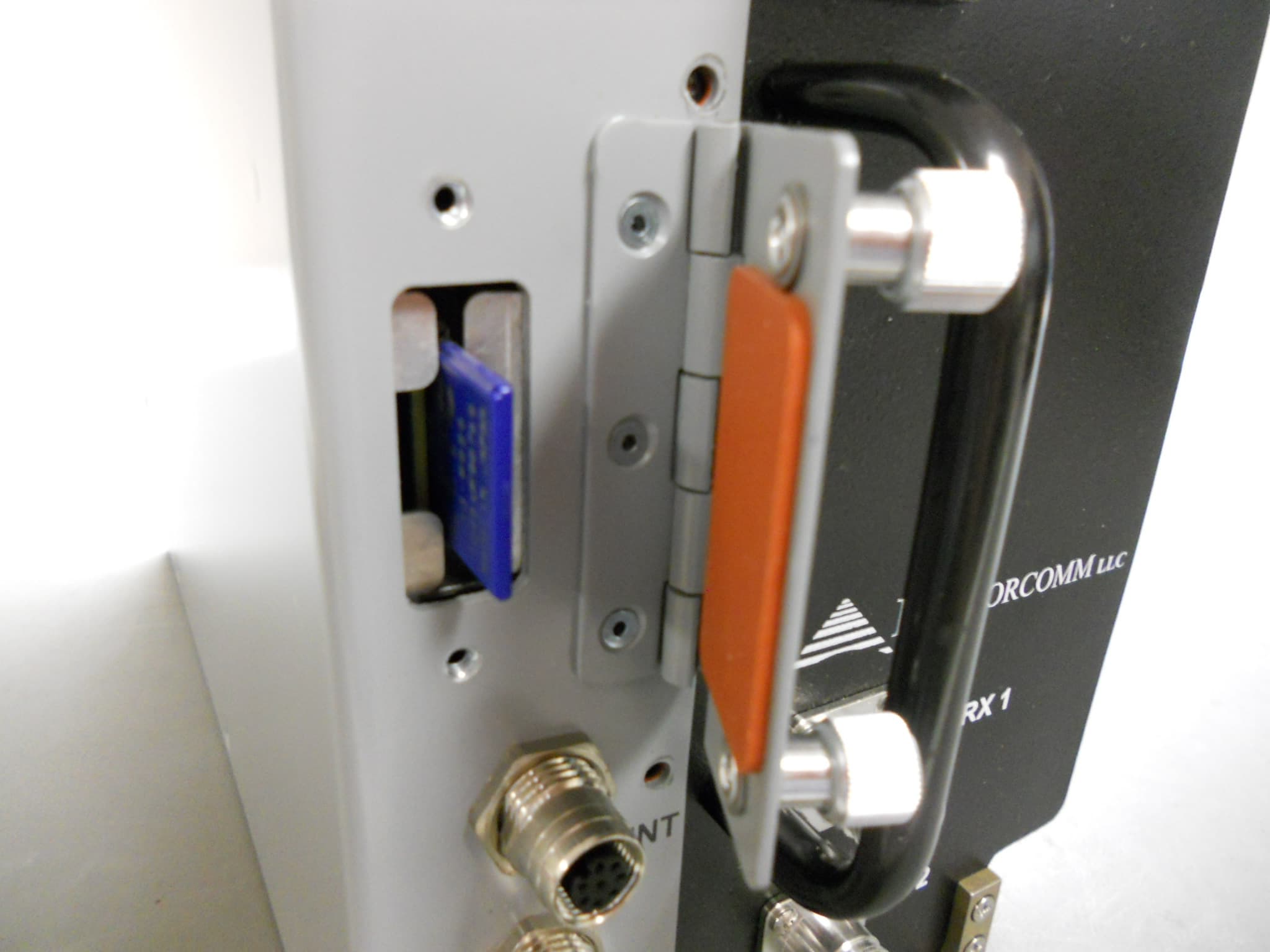
BIB63020
Nov 10, 2011Locomotive Radio
Equipment Class
TNB - Licensed Non-Broadcast Station Transmitter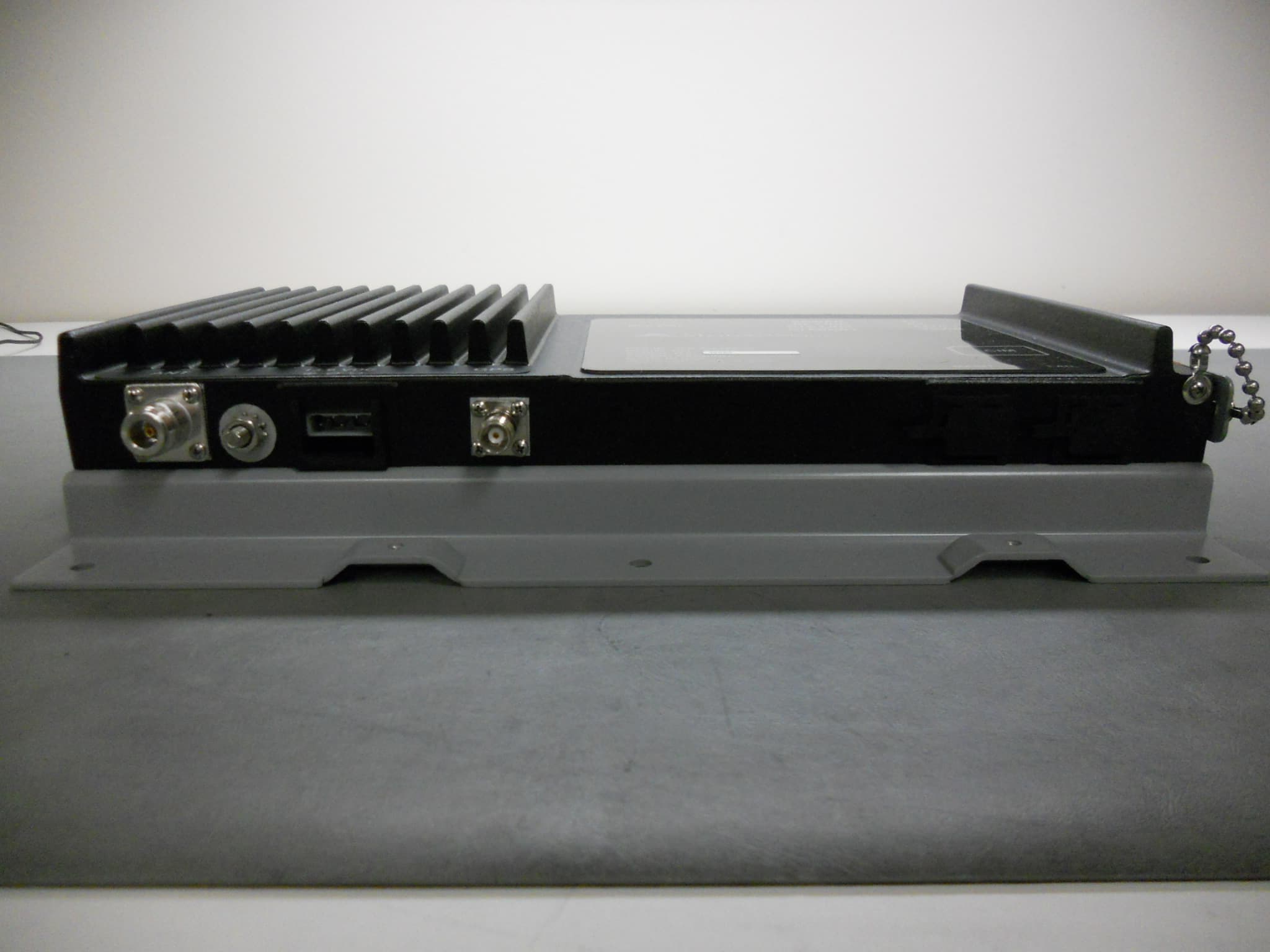
BIB63010
Oct 30, 2011Wayside Packet Data Transceiver
Equipment Class
TNB - Licensed Non-Broadcast Station Transmitter
BIB63030-24
Oct 03, 2011Packet Data Transceiver - Fixed Use - 24VDC
Equipment Class
TNB - Licensed Non-Broadcast Station Transmitter
BIB63030-48
Sep 22, 2011Packet Data Transceiver - Fixed Use - 48VDC
Equipment Class
TNB - Licensed Non-Broadcast Station Transmitter