BIB61201001Land Mobile Packet Data Transceiver
Meteorcomm LLC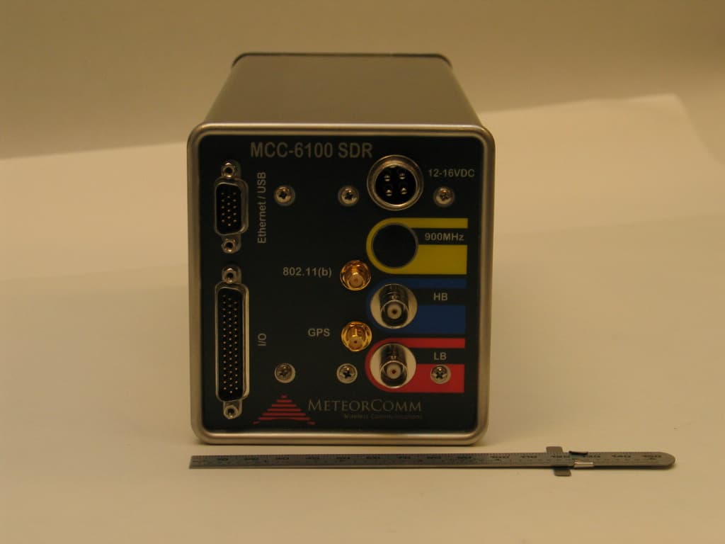
Click to zoom
Application Details
- Equipment Class
- TNB - Licensed Non-Broadcast Station Transmitter
- Date of Grant
- Mar 27, 2007
- Application Purpose
- Original Equipment
- Date of Application
- Dec 04, 2006
- Equipment Note
- Land Mobile Packet Data Transceiver
- Frequency Range
- 151.00000000 - 162.00000000
- Company
- Meteorcomm LLC
- Country
- United States
Documents & Files
Document Text
Text extracted from the exhibit documents filed with the FCC. Open a document above to read the original.
Users Manual
FCC ID: BIB61201001 OPERATION OF THE MCC-6120 SDR PACKET DATA RADIO MAN-OPS-6120 SDR-ARR PRELIMINARY December 1, 2006 Meteor Communications Corporation 22614 66 th Avenue South. Kent, WA 98032 Tel: (253) 872-2521 Fax: (253) 872-7662 E-mail: [email protected] On the Web: www.meteorcomm.com 2006 by Meteor Communications Corporation all rights reserved FCC ID: BIB61201001 GENERAL WARRANTY Meteor Communications Corporation (MCC) warrants that its products conform to the published specifications and are free from manufacturing and material defects for one year after shipment. Warranty-covered equipment that fails during the warranty period will be promptly repaired at MCC’s facility in Kent, Washington. International customers are required to pay shipping costs to the MCC facility, with Seattle as the point of U.S. entry. MCC will pay incoming U.S. duty fees. MCC will pay for shipping costs to return the equipment to the customer, with the customer paying any and all return duty fees. This warranty is contingent upon proper use of the equipment and does not cover equipment that has been modified in any way without MCC’s approval or has been subjected to unusual physical or electrical stress, or on which the original identification marks have been removed or altered. FCC ID: BIB61201001 Important Safety Instructions for Installers and Users RF Exposure Information In order to comply with Federal Communications Commission safety standards for human exposure to radio frequency (RF) energy, the following precautions must be taken: • Mount each antenna connected to the transmitter at a location such that, during transmission, no person or persons can come within the minimum separation distance specified in the chart below. Frequency Band AntennaAntenna type maximum duty cycle cmin 39 - 50 MHz 1/4 wave dipole mounted to roof of vehicle 10.00%4517.7 156 - 162 MHz 1/4 wave dipole mounted to roof of vehicle 50.00%5019.7 896-901MHz/935-940 MHz 1/4 wave dipole mounted to roof of vehicle 50.00%3011.8 896-901MHz/935-940 MHz 5/8 wave over 1/4 wave colinear mounted to roof of vehicle 50.00%4517.7 2412 - 2462 MHz3 dBi100.00%207.9 minimum separation distance • Install all antennas in accordance with manufacturer’s instructions. • Always disable the transmitter when installing or servicing an antenna or transmission line. • Mobile antennas may be installed at the center of a vehicle roof or trunk as long as the minimum separation distance is observed. • Base antennas should be installed on permanent outdoor structures. RF Exposure compliance at such sites must be addressed on a site-by-site basis. When these precautions are taken, an installation with this device satisfies the requirements for an Occupational/Controlled Exposure environment, per OET Bulletin 65. FCC ID: BIB61201001 REVISION PAGE Document Title: Operation of the MCC-6120 SDR Packet Data Radio Document Number: MAN-OM-6120 SDR-ARR Revision # Date Revision Redline 12/1/2006 Redline Release Initial Initial Release A B C D E F G H I PRELIMINARY FCC ID: BIB61201001 PRELIMINARY MCC-6120 SDR Packet Data Radio Network TABLE OF CONTENTS Title Page 1.0 INTRODUCTION .........................................................................................................1-1 1.1 Manual Organization .................................................................................................1-2 1.2 Related Documents ....................................................................................................1-3 2.0 DESCRIPTION..............................................................................................................2-4 2.1 General .......................................................................................................................2-4 2.2 Functionality Overview .............................................................................................2-5 2.3 SDR Modules.............................................................................................................2-9 2.4 Detailed Specifications ..............................................................................................2-9 2.5 Memory Organization ..............................................................................................2-12 3.0 INSTALLATION ..........................................................................................................3-1 3.1 Site Selection .............................................................................................................3-1 3.1.1 External Noise/Interference ..................................................................................3-1 3.1.2 DC Power Source..................................................................................................3-2 3.1.3 Antenna Selection .................................................................................................3-3 3.1.4 Antenna Height .....................................................................................................3-3 3.2 Equipment Installation ...............................................................................................3-5 3.2.1 Mobile Installations ..............................................................................................3-5 3.2.2 Cable Connections ................................................................................................3-5 3.2.2.1 DC Power Input..................................................................................................................... 3-6 3.2.2.2 LB/HB Connectors ................................................................................................................ 3-7 3.2.2.3 GPS Antenna ......................................................................................................................... 3-7 3.2.2.4 802.11(b) ............................................................................................................................... 3-7 3.2.2.5 …
Text truncated - open the document above for the full version.
Users Manual
RF Energy Exposure Guide for MeteorComm Two-Way Radios Installed in Vehicles or at Fixed Sites IMPORTANT BEFORE USING YOUR MOBILE 2-WAY RADIO, READ THIS GUIDE WHICH CONTAINS IMPORTANT RF ENERGY AWARENESS AND CONTROL INFORMATION AND OPERATIONAL INSTRUCTIONS TO ENSURE COMPLIANCE WITH THE FCC’S RF EXPOSURE GUIDELINES. IMPORTANT RETAIN THIS GUIDE AT THE LOCATION OF THE RADIO INSTALLATION. RF Energy Exposure Awareness and Control Information, and Operational Instructions for FCC Occupational Use Requirements NOTICE: This radio is intended for use in occupational/controlled conditions, where users have full knowledge of their exposure and can exercise control over their exposure to meet FCC limits. This radio device is NOT authorized for general population, consumer, or any other use. This 2-way radio uses electromagnetic energy in the radio frequency (RF) spectrum to provide communications between two or more users over a distance. It uses RF energy or radio waves to send and receive calls. RF energy is one form of electromagnetic energy. Other forms include, but are not limited to, sunlight and x-rays. RF energy, however, should not be confused with these other forms of electromagnetic energy, which when used improperly, can cause biological damage. Very high levels of x-rays, for example, can damage tissues and genetic material. Experts in science, engineering, medicine, health, and industry work with organizations to develop standards for safe exposure to RF energy. These standards provide recommended levels of RF exposure for both workers and the general public. These recommended RF exposure levels include substantial margins of protection. All 2-way radios marketed in North America are designed, manufactured, and tested to ensure they meet government-established RF exposure levels. In addition, manufacturers also recommend specific operating instructions to users of 2-way radios. These instructions are important because they inform users about RF energy exposure and provide simple procedures on how to control it. Please refer to the following Web sites for more information on what RF energy exposure is and how to control your exposure to assure compliance with established RF exposure limits. http://www.fcc.gov/oet/rfsafety/rf-faqs.html http://www.osha.gov/SLTC/radiofrequencyradiation/index.html MCC RF Energy Exposure Guide 1 2/14/2007 Federal Communication Commission Regulations The FCC rules require manufacturers to comply with the FCC RF energy exposure limits for mobile 2-way radios before they can be marketed in the U.S. When 2-way radios are used as a consequence of employment, the FCC requires users to be fully aware of and able to control their exposure to meet occupational requirements. Exposure awareness can be facilitated by the use of a label directing users to specific user awareness information. Your MeteorComm (MCC) 2-way radio has an RF exposure product label. Also, your MCC user manual, as well as this RF Energy Exposure Guide guide, includes information and operating instructions required to control your RF exposure and to satisfy compliance requirements. Compliance with RF Exposure Standard Your MCC two-way radio is designed and tested to comply with a number of national and international standards and guidelines (listed below) regarding human exposure to radio frequency electromagnetic energy. This radio complies with the IEEE and ICNIRP exposure limits for occupational/controlled RF exposure environment at duty factors of up to 50% talk-50% listen and is authorized by the FCC for occupational use. In terms of measuring RF energy for compliance with the FCC exposure guidelines, your radio antenna radiates measurable RF energy only while it is transmitting (during talking), not when it is receiving (listening) or in standby mode. Your MCC two-way radio complies with the following RF energy exposure standards and guidelines: • United States Federal Communications Commission, Code of Federal Regulations; 47CFR part 2 sub-part J • American National Standards Institute (ANSI) / Institute of Electrical and Electronic Engineers (IEEE) C95. 1-1992 • Institute of Electrical and Electronic Engineers (IEEE) C95.1-1999 Edition MCC RF Energy Exposure Guide 2 2/14/2007 RF Exposure Compliance and Control Guidelines and Operating Instructions for Vehicular Installations To control exposure to yourself and others and to ensure compliance with occupational/controlled environment exposure limits, always adhere to the following procedures. 1. Guidelines: • These user awareness instructions should accompany the device or vehicle that it is installed in when transferred to other users. • Do not use this device if the operational requirements described herein are not met. 2. Operator Instructions: • For voice operation, transmit no more than the rated duty factor of 50% of the time. To transmit (talk), push the Push-To-Talk (PTT) button. To receive calls, release the PTT button. Transmitting 50% of the time, or less, is important because this radio generates measurable RF energy exposure only when transmitting (in terms of measuring for standards compliance). • Be aware that a transmitter may operate automatically at any time when functioning as a data radio. People outside of the vehicle must maintain the recommended minimum lateral distance from the antennas at all times. It is the responsibility of the vehicle’s operator to keep bystanders beyond the minimum lateral distance from the antennas in order to comply with the FCC RF exposure limits for an uncontrolled/general population environment. • Transmit only when people outside the vehicle are at least the recommended minimum lateral distance away, as shown in Table 1, from a properly installed externally-mounted antenna. NOTE: Table 1 below lists the recommended lateral distances to be maintained between bystanders and approved, properly installed transmitting antennas (e.g., monopoles over a ground plane, or dipoles) in an uncontrolled…
Text truncated - open the document above for the full version.
Users Manual
FCC ID: BIB61201001 OPERATION OF THE MCC-6120 SDR PACKET DATA RADIO MAN-OPS-6120 SDR-ARR PRELIMINARY January 30, 2007 Meteor Communications Corporation 22614 66 th Avenue South. Kent, WA 98032 Tel: (253) 872-2521 Fax: (253) 872-7662 E-mail: [email protected] On the Web: www.meteorcomm.com 2007 by Meteor Communications Corporation all rights reserved FCC ID: BIB61201001 GENERAL WARRANTY Meteor Communications Corporation (MCC) warrants that its products conform to the published specifications and are free from manufacturing and material defects for one year after shipment. Warranty-covered equipment that fails during the warranty period will be promptly repaired at MCC’s facility in Kent, Washington. International customers are required to pay shipping costs to the MCC facility, with Seattle as the point of U.S. entry. MCC will pay incoming U.S. duty fees. MCC will pay for shipping costs to return the equipment to the customer, with the customer paying any and all return duty fees. This warranty is contingent upon proper use of the equipment and does not cover equipment that has been modified in any way without MCC’s approval or has been subjected to unusual physical or electrical stress, or on which the original identification marks have been removed or altered. FCC ID: BIB61201001 Important Safety Instructions for Installers and Users RF Exposure Compliance CAUTION Before installation and use of your mobile 2-way radio, read the MeteorComm RF Energy Exposure Guide which contains important RF energy awareness and control information and operational instructions to ensure compliance with the FCC’s RF exposure guidelines. IMPORTANT This radio is restricted to occupational use to satisfy FCC RF exposure limits. See the accompanying RF Energy Exposure Guide for installation and operating requirements. FCC ID: BIB61201001 REVISION PAGE Document Title: Operation of the MCC-6120 SDR Packet Data Radio Document Number: MAN-OM-6120 SDR-ARR Revision # Date Revision Redline 1/30/2007 Redline Release (with RF Energy Exposure Guide references) Initial Initial Release A B C D E F G H I PRELIMINARY FCC ID: BIB61201001 PRELIMINARY MCC-6120 SDR Packet Data Radio Network TABLE OF CONTENTS Title Page 1.0 INTRODUCTION .........................................................................................................1-1 1.1 Manual Organization .................................................................................................1-2 1.2 Related Documents ....................................................................................................1-3 2.0 DESCRIPTION..............................................................................................................2-4 2.1 General .......................................................................................................................2-4 2.2 Functionality Overview .............................................................................................2-5 2.3 SDR Modules.............................................................................................................2-9 2.4 Detailed Specifications ..............................................................................................2-9 2.5 Memory Organization ..............................................................................................2-12 3.0 INSTALLATION ..........................................................................................................3-1 3.1 Site Selection .............................................................................................................3-1 3.1.1 External Noise/Interference ..................................................................................3-1 3.1.2 DC Power Source..................................................................................................3-2 3.1.3 Antenna Selection .................................................................................................3-3 3.1.4 Antenna Height .....................................................................................................3-3 3.2 Equipment Installation ...............................................................................................3-5 3.2.1 Mobile Installations ..............................................................................................3-5 3.2.2 Cable Connections ................................................................................................3-5 3.2.2.1 DC Power Input..................................................................................................................... 3-6 3.2.2.2 LB/HB Connectors ................................................................................................................ 3-7 3.2.2.3 GPS Antenna ......................................................................................................................... 3-7 3.2.2.4 802.11(b) ............................................................................................................................... 3-7 3.2.2.5 I/O Port.................................................................................................................................. 3-7 3.2.2.6 Ethernet/USB Connector ..................................................................................................... 3-11 3.3 Power-Up Sequence.................................................................................................3-13 3.3.1 Connect Operator Terminal ................................................................................3-13 3.3.2 Power Connection ...............................................................................................3-13 3.3.3 Initialization Procedures .....................................................................................3-14 3.3.3.1 Verify Device Type ............................................................................................................. 3-14 3.3.3.2 Ver…
Text truncated - open the document above for the full version.
Attestation Statements
Meteor Communications Corporation FCC ID: BIB61201001 Exhibit 4 General Information General Information for Non-Broadcast Transmitter (Part 90) Device, §2.1033(c)(10) (1) Manufacturer/Applicant: Meteor Communications Corporation 22614 66 th Avenue South Kent, WA 98032 (2) FCC ID: BIB61201001 Equipment Class: Licensed Non-Broadcast Transmitter (3) Installation and Instruction Manuals: See Exhibit 14. (4) Types of Emission: see below (5) Frequency Ranges: see below (6) Operating Power Levels: see below Item FCC Rule part Frequency range (MHz) Output (W) Frequency Tolerance Emission Designator Waveform/ Channel Sp 190 39-50 MHz100 20 ppm20K0F1D 19.2 GMSK 25kHz 290 39-50 MHz100 20 ppm14K4F1D 9.6 GMSK 25kHz 390 39-50 MHz100 20 ppm8K00G1D 4k BPSK 25kHz 490 151-162 MHz33 2.5 ppm20K0F1D 19.2 GMSK 25kHz 590 151-162 MHz33 2.5 ppm14K4F1D 9.6 GMSK 25kHz 690.210 151-162 MHz33 2.5 ppm11K0F1D 9.6 GMSK 12.5kHz 790 151-162 MHz33 2.5 ppm16K0F3E Voice 25kHz 890.210 151-162 MHz33 2.5 ppm11K0F3E Voice 12.5kHz 990 151-162 MHz33 2.5 ppm6K50F1D 4.8 GFSK 12.5kHz Orange = line items on Grant Yellow = emissions that are covered under a wider BW emission designator. 4-1 Meteor Communications Corporation FCC ID: BIB61201001 (7) Maximum power ratings for each band: 39-50 MHz 300W 151-162 MHz 500W (8) DC voltages applied and current into final RF amplifier: see Test reports for respective bands, Exhibits 8LB and 8HB. (9) Tune-up Procedure: See Exhibit 11. (10) Schematic diagrams: See Exhibit 6B. Description of circuits: See Exhibit 12 (11) Photograph of FCC label: see Exhibit 1. (12) External and internal photographs: See Exhibit 5. (13) Description of Digital modulation techniques: see discussion below Digital Modulation Techniques. (14) Data required by §§2.1046 through 2.1057: See Test Report, Exhibit 8. (18) Software Defined Radio: See Exhibit 3. Additional Information Production Plans, per §2.1033: Quantity production is planned. Application References, per §2.1061: CKC Laboratories, Inc. 22116 23rd Drive S.E. Bothell, WA 98021 . Data submittal procedure: per 47CFR2, Subpart J 4-2 Meteor Communications Corporation FCC ID: BIB61201001 Necessary Bandwidth Calculations for Applicable Emission Designators Necessary Bandwidth and Emission Designators, Digital Modulation TypesFrom 47CFR2.202 4000 bps CE-BPSK 4800 bps 0.5 GFSK 4800 bps 0.5 GFSK 9600 bps .30 GMSK 9600 bps .33 GMSK 9600 bps 1.0 GMSK 19200 bps .22 GMSK Channel spacing >> 20/25/ 30 kHz12.5kHz12.5kHz12.5kHz12.5kHz25kHz20/25/ 30kHz Mask C160:Mask DMask J160:Mask D 900:Mask JMask CMask C Digital information rateR40004800480096009600960019200 Peak DeviationD170017002400240024004800 Signaling StatesS2222222 ConstantK10.50.50.30.3310.22 Formula 2RK/log2( S)R/log2(S)+2DK R/log2(S)+2DK R/log2(S)+ 2DK R/log2(S)+ 2DK R/log2(S)+2D KR/log2(S)+2DK Necessary BWBn80006500650011040111841440021312 Applicable Bands39-50151-162,UHF151-162,UHF151-162,UHFUHF39-50,151-162 39-50,151-162 max authorized BW20kHz20kHz, 13.6kHz 20kHz, 13.6kH z20kHz, 13.6kHz13.6kHz20kHz20kHz Emission Designator8K00G1D6K50F1D6K50F1D11K0F1D11K2F1D14K4F1D20K0F1D Necessary Bandwidths and Emission Designators, Voice Analog FMAnalog FM Channel spacing25kHz12.5kHz Modulation BW, Hzfm30003000 Max Deviation, HzD50002500 ConstantK11 Formula2fm+2DK2fm+2DK Necessary BW, HzBn1600011000 Applicable Bands151-162151-162, UHF Max Authorized BW20kHz20kHz, 13.6kHz Emission Designator16K0F3E11K0F3E Digital Modulation Techniques per §2.1033 (13) The basis of the transmitter carrier generator and modulator is a direct digital synthesis (DDS) integrated circuit. The DDS contains a numerically controlled oscillator (NCO) that accumulates (integrates) carrier phase at a 230.4 MHz sample rate with a modulus of two Pi. The fixed part of the phase increment for the accumulator sets the carrier frequency of the NCO and a modulation increment added or subtracted from the fixed increment, at 384k samples per second, modulates the carrier phase relative to the fixed phase increment to produce phase shift keying (PSK) or frequency shift keying (FSK). The instantaneous phase samples output from the NCO are applied to a ROM look up table that outputs sinusoidal values. Finally, these values are applied to a 230.4 M sample/sec digital to analog converter (DAC). Analog filters farther along in the signal path remove DAC harmonic distortion and other spurii. 4-3 Meteor Communications Corporation FCC ID: BIB61201001 For the 39-50 MHz transmitter band, the DDS DAC output signal is generated directly on the assigned carrier frequency. For the 151-162 MHz transmitter band, the DDS outputs an intermediate frequency (I.F.) band from 61 to 68 MHz. With one exception, the MCC-6101 digital data modulation waveforms are all Gaussian- filtered frequency shift keying (GFSK). The modulation pre-filters have Gaussian spectral characteristics with linear phase response. They are designed according to the selected bit rate, peak deviation and the spectral limits imposed by the FCC masks. When the peak-to-peak frequency deviation equals half the bit rate, the modulation is called Gaussian Minimum Shift Keying (GMSK). For GFSK, the incoming data bits are converted to bipolar rectangular pulses with amplitude +1 or -1. These are then low pass filtered, amplitude scaled and interpolated to the modulation sample rate by the Gaussian filter. The result is added to the NCO carrier phase increment. One additional data modulation waveform is constant envelope binary phase shift keying (CEBPSK). In this case, the original data bits are converted to bipolar impulses rather than rectangular pulses. When applied to the NCO at a prescribed amplitude, in the same manner previously described, the NCO integrates the impulses to linearly advance or retard the carrier phase exactly 180 degrees over the duration of the bit. Voice modulation begins by digitizing the amplified microphone voice waveform. The samples are then passed through a digital pre-emphasis filter followed …
Text truncated - open the document above for the full version.
External Photos
Meteor Communications Corporation FCC ID: BIB61201001 Exhibit 5 Equipment Photos Exhibit 5A – External Views Exhibit 5B – Internal Views and Board Details 5-1 Meteor Communications Corporation FCC ID: BIB61201001 Exhibit 5A- External Views 5-2
ID Label/Location Info
Meteor Communications Corporation FCC ID: BIB61201001 Exhibit 1 FCC Label and Location Information Figure 1.1 FCC Label Label Material: Silver Matte Mylar #7222 Clear Matte Imprintable Mylar Overlay #PM-200-CM/T Adhesive: Permanent, pressure activated Process: Hot Stamp Thickness: 4mils total Color: Black Lettering Actions: Laminate, die cut, strip, waste 1-1 Meteor Communications Corporation FCC ID: BIB61201001 Figure 1.2 FCC Label location Figure 1.3 FCC Label location 1-2
ID Label/Location Info
Meteor Communications Corporation FCC ID: BIB61201001 Exhibit 1 (Amended) FCC Label and RF Exposure Label Location Information Figure 1.1 FCC Label Label Material: Silver Matte Mylar #7222 Clear Matte Imprintable Mylar Overlay #PM-200-CM/T Adhesive: Permanent, pressure activated Process: Hot Stamp Thickness: 4mils total Color: Black Lettering Actions: Laminate, die cut, strip, waste 1-1 Meteor Communications Corporation FCC ID: BIB61201001 Figure 1.2 RF Exposure Label Label Material: Silver Matte Mylar #7222 Clear Matte Imprintable Mylar Overlay #PM-200-CM/T Adhesive: Permanent, pressure activated Process: Hot Stamp Thickness: 4mils total Color: Black Lettering Actions: Laminate, die cut, strip, waste 1-2 Meteor Communications Corporation FCC ID: BIB61201001 Figure 1.3 FCC and RF Label locations– Radio Unit Figure 1.4 FCC and RF Label locations – Radio Unit 1-3 Meteor Communications Corporation FCC ID: BIB61201001 Figure 1. RF Label location – Microphone 1-4
Internal Photos
Meteor Communications Corporation FCC ID: BIB61201001 Exhibit 5B - Photos - Internal Views Figure 5B-1 Front side view with cover removed Figure 5B-2 Front side view with cover removed 5B-1 Meteor Communications Corporation FCC ID: BIB61201001 Figure 5B-3 Top side view with cover removed Figure 5B-4 Rear side view with cover removed 5B-2
Internal Photos
Meteor Communications Corporation FCC ID: BIB61201001 Exhibit 5C- Internal Views (cont) Internal Equipment Photos - CMU Figure 5C-1 CMU Board, top, with 802.11(b) and GPS modules installed 5C-1 Meteor Communications Corporation FCC ID: BIB61201001 Figure 5C-2 CMU Board, top, with 802.11(b) and GPS modules removed Figure 5C-3 CMU Board, bottom 5C-2
Internal Photos
Meteor Communications Corporation FCC ID: BIB61201001 Exhibit 5D- Internal Views (cont) Internal Equipment Photos – Low Band Transmitter Figure 5D-1 Low Band Board, top, with shield removed Figure 5D-2 Low Band Board, bottom 5D-1 Meteor Communications Corporation FCC ID: BIB61201001 Figure 5D-4 Low Band Assembly, top, with shield installed Figure 5D-2 Low Band Assembly, top, with cover installed 5D-2
Internal Photos
Meteor Communications Corporation FCC ID: BIB61201001 Exhibit 5E- Internal Views (cont) Internal Equipment Photos – High Band Transmitter Figure 5E-1 High Band Board, top, with shields uninstalled Figure 5E-2 High Band Assembly, top, with shields installed 5E-1 Meteor Communications Corporation FCC ID: BIB61201001 Figure 5E-3 High Band Board, bottom Figure 5E-4 High Band Assembly, top, with shields installed 5E-2 Meteor Communications Corporation FCC ID: BIB61201001 Figure 5E-5 High Band Assembly, rear, (RF power amp visible) Figure 5E-6 High Band Assembly, rear 5E-3
Internal Photos
Meteor Communications Corporation FCC ID: BIB61201001 Exhibit 5F- Internal Views Internal Equipment Photos – 802.11(b) Transceiver Figure 5F-1 DPAC 802.11(b) Board, top Figure 5F-2 DPAC 802.11(b) Board, bottom 5F-1
RF Exposure Info
Meteor Communications Corporation FCC ID: BIB61201001 Exhibit 13 RF Exposure 13.1 Determination of Need for Routine Environmental Evaluation for RF Exposure per §2.1091(c) It is the view of MCC that the MCC-61201001 is not subject to routine environmental evaluation for RF exposure. While it is intended for use in Part 90 applications, it is not designed for use in the Specialized Mobile Radio Service. 13.2 RF Exposure Calculations The MCC-61201001 transmitter operates in three (3) frequency bands: 39-50 MHz, 151- 162 MHz, and 2412-2462 MHz. Per Figure 1 of OET Bulletin 65, the FCC limit for Maximum Permitted Exposure (MPE) in an Occupational/Controlled Exposure environment to the power densities, S: S = 1mW/cm 2 for the frequency range of 30-300 MHz, S = f/300 mW/cm 2 for the frequency range of 300-1500 MHz, S = 5mW/cm 2 for the frequency range of 1500-3000 MHz, where f is expressed in MHz. The FCC power density limits for each of the subject transmit bands are expressed below. Frequency Band (MHz) MPE Power Density Limit (mW/cm^2) 39 - 50 1.0 151 - 1621.0 896 - 9013.0 935 - 9403.1 2412 - 24625.0 Note: A discussion of this subject as pertains to 896-901MHz and 935-940MHz is included here as the RF Exposure Information page from the Operators Manual will be common to all MCC-6100 variants and some versions of the 6100 family include these bands. The minimum separation required between a human and an antenna connected to an active antenna can be determined by use of the power density expression: R PG S π4 = 13-1 Meteor Communications Corporation FCC ID: BIB61201001 Where: S = power density in mW/cm 2 P = RF power into the antenna in mW G = antenna gain (unitless, linear) R = separation/distance between antenna and point of interest in cm Solved for R, the formula becomes: S PG R π4 = The charts below shows the maximum transmit power levels, duty cycles, maximum power densities and R, the calculated minimum human separation for each band. Several example antenna types are shown. Antenna gains shown are relative to an isotropic radiator. For 39-50MHz mWdBmmWdBmmWdBm Transmitter power 100000501000005010000050 120% of peak transmit power 120000120000120000 max duty cycle 10.00%10.00%10.00% Time averaged max peak power P120001200012000 antenna gain (lin/dB) G1.642.1510.00103.315.2 max power density, mW/cm2, limit per Fig 1 OET65 S1.001.001.00 R=sqrt(P*G/4*pi*S), cm 39.5897.7256.23 39.6 cm97.…
Text truncated - open the document above for the full version.
Contact Information
Applicant
Dave Herber(VP Engineering)
Technical Contact
MeteorCommNorm Shivley
[email protected](253) 872-2521
22612 66th Avenue South · Kent, Washington · United States
Non-Technical Contact
MeteorCommNorm Shivley
[email protected](253) 872-2521
Technical Specifications
| # | Rule Parts | Frequency Range | Power Output | Emission | Tolerance |
|---|---|---|---|---|---|
| 6 | 9 | 151 MHz - 162 MHz | 33 W | 11K0F3E | 2.5 ppm |
Other Applications from Meteorcomm LLC

BIB54505003-01
Feb 23, 2012Packet Data Radio Transceiver - Fixed or Mobile
Equipment Class
TNB - Licensed Non-Broadcast Station Transmitter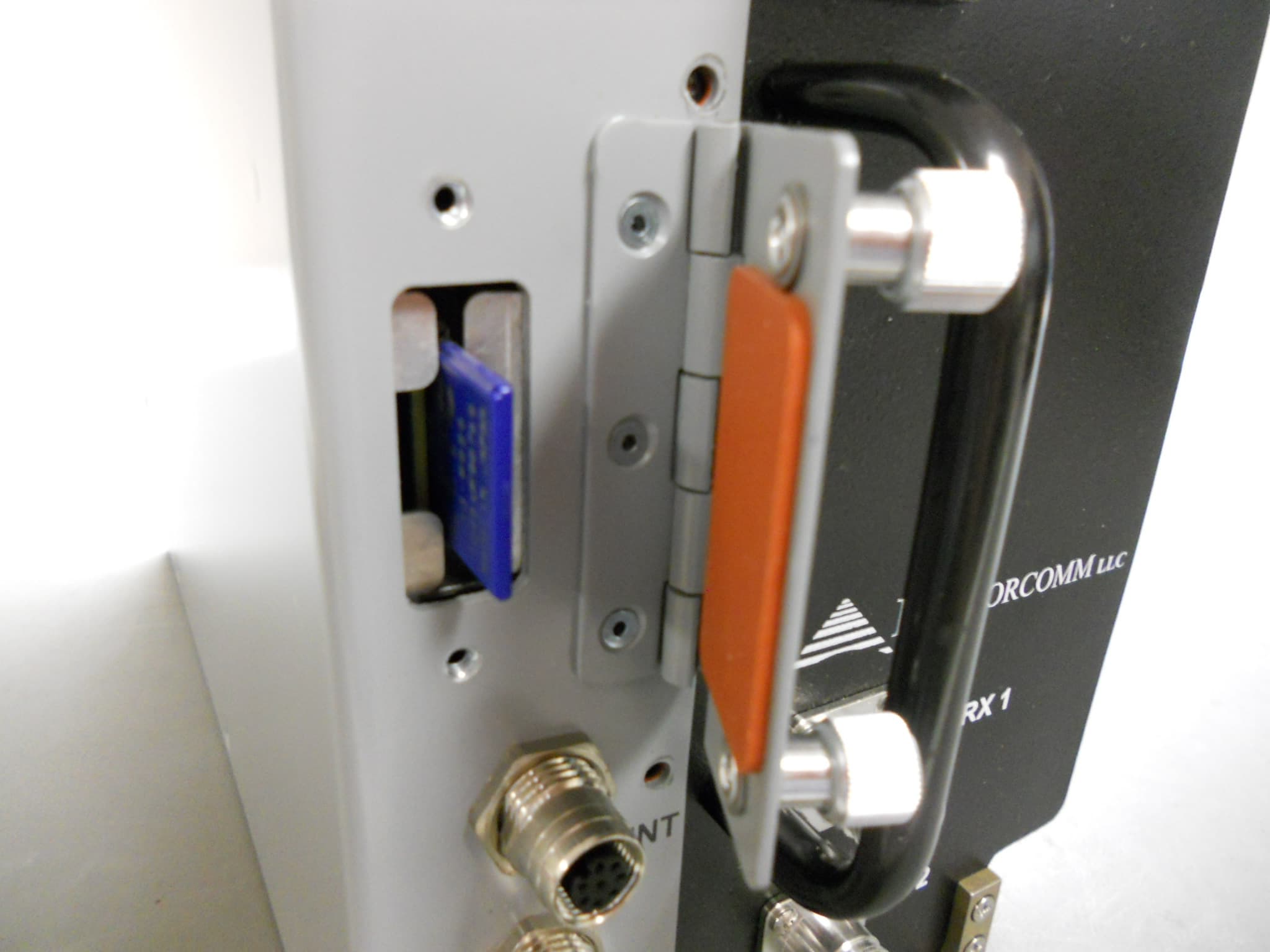
BIB63020
Nov 10, 2011Locomotive Radio
Equipment Class
TNB - Licensed Non-Broadcast Station Transmitter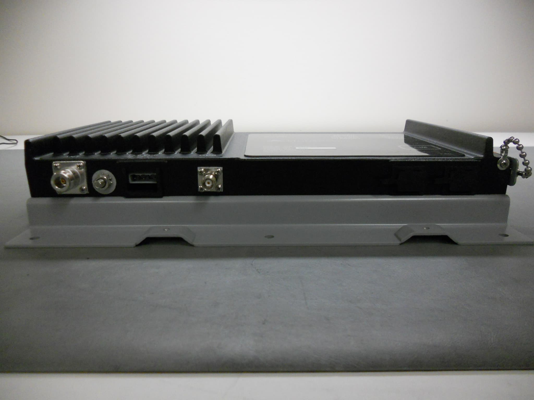
BIB63010
Oct 30, 2011Wayside Packet Data Transceiver
Equipment Class
TNB - Licensed Non-Broadcast Station Transmitter
BIB63030-24
Oct 03, 2011Packet Data Transceiver - Fixed Use - 24VDC
Equipment Class
TNB - Licensed Non-Broadcast Station Transmitter
BIB63030-48
Sep 22, 2011Packet Data Transceiver - Fixed Use - 48VDC
Equipment Class
TNB - Licensed Non-Broadcast Station Transmitter