BJ4-400TX400TX Door Chime Transmitter
HeathCo LLC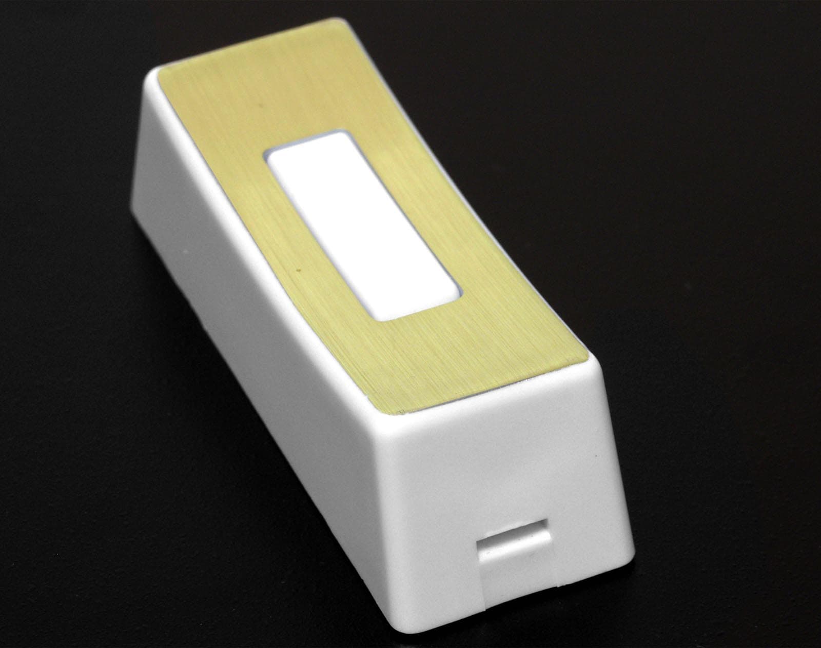
Click to zoom
Application Details
- Equipment Class
- DSC - Part 15 Security/Remote Control Transmitter
- Date of Grant
- Aug 10, 2004
- Application Purpose
- Original Equipment
- Date of Application
- Aug 10, 2004
- Equipment Note
- 400TX Door Chime Transmitter
- Frequency Range
- 315.00000000 - 315.00000000
- Company
- HeathCo LLC
- Country
- United States
Documents & Files
Document Text
Text extracted from the exhibit documents filed with the FCC. Open a document above to read the original.
Users Manual
© 2004 DESA Specialty Products TM 598-1186-01 FEATURES Selectable Channels Up to 8 channels reduces the possibility of interference from other wireless devices. Volume Control To adjust the sound output to the desired level. On-Off Switch Shuts off all but auxiliary outlet. Long-Range Operation Up to 100 feet (operating range may be affected by material and construction of home). Auxiliary Outlet 120 VAC, 5 AMP. (MAX.) INSTALLATION INSTRUCTIONS FOR WIRELESS STROBE CHIME 34-B&LE-34manual-072704.indd 17/27/04 11:44:13 AM 598-1186-01 CHANNEL SETTING Your new TRINE wireless door chime uses a digital coding system to create eight selectable channels. It is not necessary to change the set- ting, since the wireless door chime is factory pre-set. However, if interference from other devices occurs or if you wish to match to other TRINE wireless door chimes, the channel must have the same settings to operate properly. On the back of the chime you will fi nd connectors numbered one through three. These are for your channel selections. Simply remove one or more connectors to set a new channel. To change the push button security code, remove one or more of the connectors (1 through 3) on the push button. You must also remove the corresponding connectors on the chime receiver (also 1 through 3). If your chime receiver has more connectors (1 through 6), use only the fi rst 3 (1 through 3). It does not matter which connector(s) you remove on the push button. Just be sure they have the same corresponding numbers as the connector(s) that you will remove from the receiver. If connector numbers do not match, your system will not work. SUGGESTION: Begin by removing just one push button connec- tor and one matching chime connector. Test to see if this eliminated the false triggering problem. If false triggering still occurs, repeat process. 321 1 2 3 ON/OFF CONNECTORS VOLUME CONTROL AUX. OUTLET -2- The push button enclosed is an eight (8) note Westminster push button which will give you 8 fl ashes combined with an 8-note Westminster melody. 34-B&LE-34manual-072704.indd 27/27/04 11:44:15 AM OPERATION On the side of the chime you will fi nd an on/off switch. Slide switch to ON position. The volume control is also located on the side of the chime. To adjust volume, simply slide to desired volume setting. There is an electric receptacle on the opposite side of the chime, providing additional convenience. INSTALLING THE CHIME(S) Place the chime or chimes in logical location (that will afford the great- est usefulness). You need merely plug in to an electrical outlet. Do not place chimes near metal objects such as refrigerators, cabinets or washing machines. Doing so may prevent signal from being clearly received. MOUNTING THE PUSH BUTTON(S) Select an appropriate location near the entrance door. Using a fl at head screwdriver, press the tab on the bottom of the push button, lift the back plate and use it as a template to mark the mounting hole locations. Drill two 3/16” diameter holes, align the back with the holes. Using the screws provided, attach the push button to the surface. Snap the push button housing in place over the mounted back. 598-1186-01 -3- INSTALLING BATTERIES INTO PUSH BUTTON(S) Your new Strobe Chime push button uses a 12 volt battery (Trine A-23). Simply insert into battery compartment by lifting back lid, inserting and closing. 34-B&LE-34manual-072704.indd 37/27/04 11:44:16 AM MAINTENANCE Always replace old or weak battery In push button. Keep chime dry. If wet, dry immediately. Do not use cleaning solvents on electronic products. Solvents contain chemicals that can damage circuitry. Use damp towel or rag to clean. Dry immediately. Regulatory Information This device (H8A34RX or BJ4-400SERIESTX) complies with Part 15 of the FCC Rules and RSS-210 of Industry Canada. Operation is subject to the following two conditions: (1) this device may not cause harmful interference, and (2) this device must accept any interference received, including interference that may cause undesired operation. The user is cautioned that changes or modifi cations not expressly approved by the party responsible for regulatory compliance could void the user’s authority to operate the equipment. Technical Service (Do Not Send Products) If you experience a problem, follow this guide. You may also want to visit our Website at: www.desatech.com. If the problem persists, call* for assistance at 1-800-858-8501, 7:30 AM to 4:30 PM CST (M-F). You may also write* to: DESA Specialty Products TM P.O. Box 90004, Bowling Green, KY 42102-9004 ATTN: Technical Service Specialty Products * If contacting Technical Service, please have the following information available: Model Number, Date of Purchase, and Place of Purchase. No Service Parts Available for this Product 598-1186-01 -4- 34-B&LE-34manual-072704.indd 47/27/04 11:44:17 AM 598-1186-01 -5- DESA Specialty Products TM reserves the right to discontinue and to change specifi cations at any time without notice without incurring any obligation to incorporate new features in previously sold products. ONE YEAR LIMITED WARRANTY This is a “Limited Warranty” which gives you specifi c legal rights. You may also have other rights which vary from state to state or province to province. For a period of one year from the date of purchase, any malfunction caused by factory defective parts or workmanship will be corrected at no charge to you. Batteries are not covered. To obtain a refund or a replacement, return the product to the place of purchase. Not Covered - Repair service, adjustment and calibration due to mis- use, abuse or negligence, light bulbs and other expendable items are not covered by this warranty. Unauthorized service or modifi cation of the product or of any furnished component will void this warranty in its entirety. This warranty does not include reimbursement for inconve- nience, installation, setup time, loss of use, or unauthorized service. This warranty covers only DESA Special…
Text truncated - open the document above for the full version.
Block Diagram
REF. No: BJ4-64WDB42TX & BJ4-64WDB43TX Transmitter Circuit Block Diagram Power Supply (Two CR1220 Batteries - 6VDC) ENCODER IC (120kHz) Oscillator (315MHz) Antenna (Helical, Internal) 1/14/20036443 & 6442 Block Diagram.xls
ID Label/Location Info
P/N: 390-0034XX-TX1A REV: A SCALE: 2 : 1 FINISH SIZE: 26mm (W) X 17mm (H) BACKGROUND: WHITE LETTER: BLACK MATERIAL: PAPER WITH WATER-PROOF REMARK: ROUND CORNER R=0.5 MM DATE: JULY 29, 2004 26 mm 17 mm FCC ID: BJ4-400TX CAN: 3984A-400TX This device complies with Part 15 of the FCC Rules. Operation is subject to the following two conditions: (1) this device may not cause harmful interference, and (2) this device must accept any interfer- ence received, including interference that may cause undesired operation. DESA Specialty Products MADE IN CHINA Bowling Green, KY 390-0034XX-TX1A 400TX TM
Operational Description
8/11/2004 400TX 400TX Wireless Transmitter Model Number: 400TX Specifications: • Input: 12 volt battery, type A23 • Circuit voltage: ~5.0 volts DC. Battery output is regulated by a series regulator power supply circuit (transistor & zener diode). • Radio Frequency: 315 MHz • User-selectable address codes: 8 Theory of Operation: The remote is normally off with the RF transmission starting when the pushbutton is depressed momentarily. When the normally open pushbutton is depressed, it connects the circuit the battery, thereby completing the circuit. When circuit is completed, the encoder outputs a 3 KHz 12-bit transmission to the RF tank circuit transmitting the information on a 315 MHz carrier frequency. The encoder continues to transmit as long as the pushbutton is depressed. The 12-bit output consists of an 8-bit address and 4 bits of data. The user-selectable address is set with header jumpers 1, 2, and 3. The other address lines are permanently set low. The 400TX utilizes the same size printed circuit board, similar power supply circuit, similar encoder IC, and RF tank circuit as the WB-94A-TX. The circuitry and component values are exactly the same.
Parts List/Tune Up Info
400TX LIST QTY 012-P001BATTERY ALKALINE 12V A231 204-1307BATTERY CONTACT (+)1 204-1309BATTERY CONTACT (-)1 006-0563-12RES. C.F. 56K OHM 0.25W 5%1 006-MGR0115F-ABDRES. SMD 0603 1.1M 1% 0.8x1.61 006-MGR0153J-ABDRES SMD 0603 15K 5% 0.8X1.61 006-MGR0220J-ABDRES. SMD 0603 22R 5% 0.8x1.61 006-MGR0273J-ABDRES. SMD0603 27K OHM 5% 1/16W1 021-C0200J-050BDCER. CAP. 20PF SMD0603 NPO2 021-C02R2C-050BDCAP 0603 2.2P NPO +/-0.25 50V1 021-C0470J-050BDCER. CAP. 47PF SMD0603 NPO1 021-C04R7C-050BDCTC COG 4.7PF SMD0603 NPO1 021-C05R6C-050BDCTC COG 5.6PF SMD0603 NPO1 021-Y5103M-025BDC.CAP.Y5V 0.01UF 20% 25V 06031 031-P001-01TRIMMER CAP. 2.0-5pf DIA:5mm1 045-P006-01CHOKE COIL 1.5uH AXIAL 6.0mm1 056-6V2-E-SC-CGZENER 6.2V SMD 5% 0.5W1 064-0665-B130TACT SWITCH 6X6X5 130G SMD1 344-P072ANTENNA WIRE 16 SOLID WITHOU T1 389-P064-01XXPARTS REFER 388-P064-01XX1 417-BTH10LT1-0SANPN-MMBTH10LT1 SMD1 417-MMBT3904-0SATR MMBT3904 NPN SOT-231 432-P002-01JUMPER PLUG 2P CLOSE TYPE3 432-P027PIN HEADER 3 PINx2 DUAL ST1 446-P001DIE VD5012/HT12E1 092-2331-2W12TOP CABINET 400/405 WHITE1 092-2332-2W11REAR CABINET 400/405 WHITE1 092-2333-2W11PUSH BUTTON 405 WHITE1 092-2334-2W11SCREW CAP 400/405 WHITE1 810-P076SCREW M2.6X6 PA SELF TAPPING1 Heath Company Ltd. 8/11/200434-B 1
Test Report
Master:PT15-Sub-C-15231 Date: November 12, 2001 Test Report: 4W27178.1 Applicant: Desa Specialty LLC P.O. Box 90004, 2901 Industrial Avenue, Bowling Green, KY. 42102, USA Equipment Under Test: 400TX Door Chime Transmitter (EUT) FCC ID: BJ4-400TX In Accordance With: FCC Part 15, Subpart C, 15.231 Tested By: Nemko Canada Inc. 303 River Road, R.R. 5 Ottawa, Ontario K1V 1H2 Authorized By: Kevin Carr, EMC/EMI/Wireless Specialist Date: 30 July 2004 Total Number of Pages: 16 Nemko Canada Inc. FCC PART 15, SUBPART C, 15.231 PROJECT NO.: 4W27178.1 EQUIPMENT: 400TX Door Chime Transmitter Page 2 of 16 Table of Contents Section 1. Summary of Test Results ...................................................................................3 Section 2. Equipment Under Test .......................................................................................5 Section 3. Transmission Requirements ..............................................................................6 Section 4. Radiated Emissions .............................................................................................8 Section 5. Occupied Bandwidth ........................................................................................13 Section 6. Block Diagram...................................................................................................15 Section 7. Test Equipment List ..........................................................................................16 Nemko Canada Inc. FCC PART 15, SUBPART C, 15.231 PROJECT NO.: 4W27178.1 EQUIPMENT: 400TX Door Chime Transmitter Page 3 of 16 Section 1. Summary of Test Results General All measurements are traceable to national standards. These tests were conducted on a sample of the equipment for the purpose of demonstrating compliance with Part 15, Subpart C. All tests were conducted using measurement procedure ANSI C63.4-1992. Radiated emissions are made on an open area test site. A description of the test facility is on file with the FCC. THIS TEST REPORT RELATES ONLY TO THE ITEM(S) TESTED. THE FOLLOWING DEVIATIONS FROM, ADDITIONS TO, OR EXCLUSIONS FROM THE TEST SPECIFICATIONS HAVE BEEN MADE. See “ Summary of Test Data”. TESTED BY: ______________________________ DATE: 30 July 2004 Chris Maidens, EMC Specialist Nemko Canada Inc. authorizes the above named company to reproduce this report provided it is reproduced in its entirety and for use by the company’s employees only. Any use which a third party makes of this report, or any reliance on or decisions to be made based on it, are the responsibility of such third parties. Nemko Canada Inc. accepts no responsibility for damages, if any, suffered by any third party as a result of decisions made or actions based on this report. This report applies only to the items tested. This report shall not be reproduced except in full without the written approval of the testing laboratory. Nemko Canada Inc., a testing laboratory, is accredited by the Standards Council of Canada. The tests included in this report are within the scope of this accreditation. Nemko Canada Inc. FCC PART 15, SUBPART C, 15.231 PROJECT NO.: 4W27178.1 EQUIPMENT: 400TX Door Chime Transmitter Page 4 of 16 Summary Of Test Data Name of Test Para. Number Results Transmission Requirements 15.231(a) Complied Radiated Emissions 15.231(b) Complied Occupied Bandwidth 15.231(c) Complied Frequency Tolerance 15.231(d) N/A (1) Periodic Alternate Field Strength Requirements 15.231(e) N/A (2) Power line Conducted Emissions 15.207 N/A (3) Justification of N/A’s (1) The EUT does not operate in the frequency range of 40.66 – 40.70 MHz. (2) The EUT does not periodically transmit at predetermined intervals. (3) The EUT is battery powered. Test Conditions: Indoor Temperature: 24° C Humidity: 48 % Outdoor Temperature: 27° C Humidity: 58% Nemko Canada Inc. FCC PART 15, SUBPART C, 15.231 PROJECT NO.: 4W27178.1 EQUIPMENT: 400TX Door Chime Transmitter Page 5 of 16 Section 2. Equipment Under Test General Equipment Information Manufacturer: Desa Specialty LLC Company Number: 3984A Model No.: 400TX Serial No.: None Date Received In Laboratory: July 28, 2004 Nemko Identification No.: Item no. 1 Test Voltage 12V (single battery powered) Frequency Range (or fixed frequency): 315 MHz, Fixed Field Strength (distance): 67.7dBuV/m @ 3m Occupied Bandwidth (99% BW): 22.3kHz Type of Modulation: PCM Emission Designator (TRC-43:) 22K3L1D Nemko Canada Inc. FCC PART 15, SUBPART C, 15.231 PROJECT NO.: 4W27178.1 EQUIPMENT: 400TX Door Chime Transmitter Page 6 of 16 Section 3. Transmission Requirements Para. No.: 15.231(a) Test Performed By: Chris Maidens Date of Test: July 29, 2004 Minimum Standard: 15.231(a) Continuous transmissions such as voice, video or data transmissions are not permitted. 15.231(a)(1) A manually operated transmitter shall employ a switch that will automatically deactivate the transmitter within not more than 5 seconds after being released. 15.231(a)(2) A transmitter activated automatically shall cease transmission within 5 seconds of activation. 15.231(a)(3) Periodic transmissions at regular pre-determined intervals are not permitted. However polling or supervisory transmissions to determine system integrity of transmitters used in security or safety applications are allowed if the periodic rate of transmission does not exceed one transmission of not more than one second duration per hour for each transmitter. 15.231(a)(4) Intentional radiators, which are employed for radio control purposes during emergencies involving fire, security of goods, and safety of life, when activated to signal an alarm, may operate during the pendency of the alarm. Test Results: Complied Test Data: Compliance was determined by verification of technical specifications and a functional test on the equipment. Nemko Canada Inc. FCC PART 15, SUBPART C, 15.231 PROJECT NO.: 4W27178.1 EQUIPMENT: 400TX Door Chime Transmitter Page 7 of 16 Rationale for Compliance with Transmission Requirements 15.231(a) N/…
Text truncated - open the document above for the full version.
Contact Information
Applicant
Jeff Bessinger(Associate Regulatory Engineer)
Technical Contact
Non-Technical Contact
Nemko Canada Inc.Ruby Dulmage
[email protected]613-737-9680
Test Firm
Nemko Canada Inc. (Ottawa)Charles Neal
Technical Specifications
| # | Rule Parts | Frequency Range | Power Output |
|---|---|---|---|
| 1 | 15.231 | 315 MHz - 315 MHz | - |
Other Applications from HeathCo LLC

BJ4-9309
Apr 01, 2020Connected LED video security motion light
Equipment Class
DTS - Digital Transmission System
BJ4-9000
Mar 25, 2020Connected Wired Decorative Motion Light
Equipment Class
DTS - Digital Transmission System
BJ4-WLTRX9600
Jan 05, 2020Video Doorbell with 2.4GHz wifi
Equipment Class
DTS - Digital Transmission System
BJ4-WLTX204
Jul 19, 2015Wireless Doorbell extender Kit
Equipment Class
DSC - Part 15 Security/Remote Control Transmitter
BJ4-WLTX208
Jul 06, 2015Wireless Door Chime Transmitter
Equipment Class
DSC - Part 15 Security/Remote Control Transmitter