BJ4-60WCP07TXWireless Control Panel
HeathCo LLC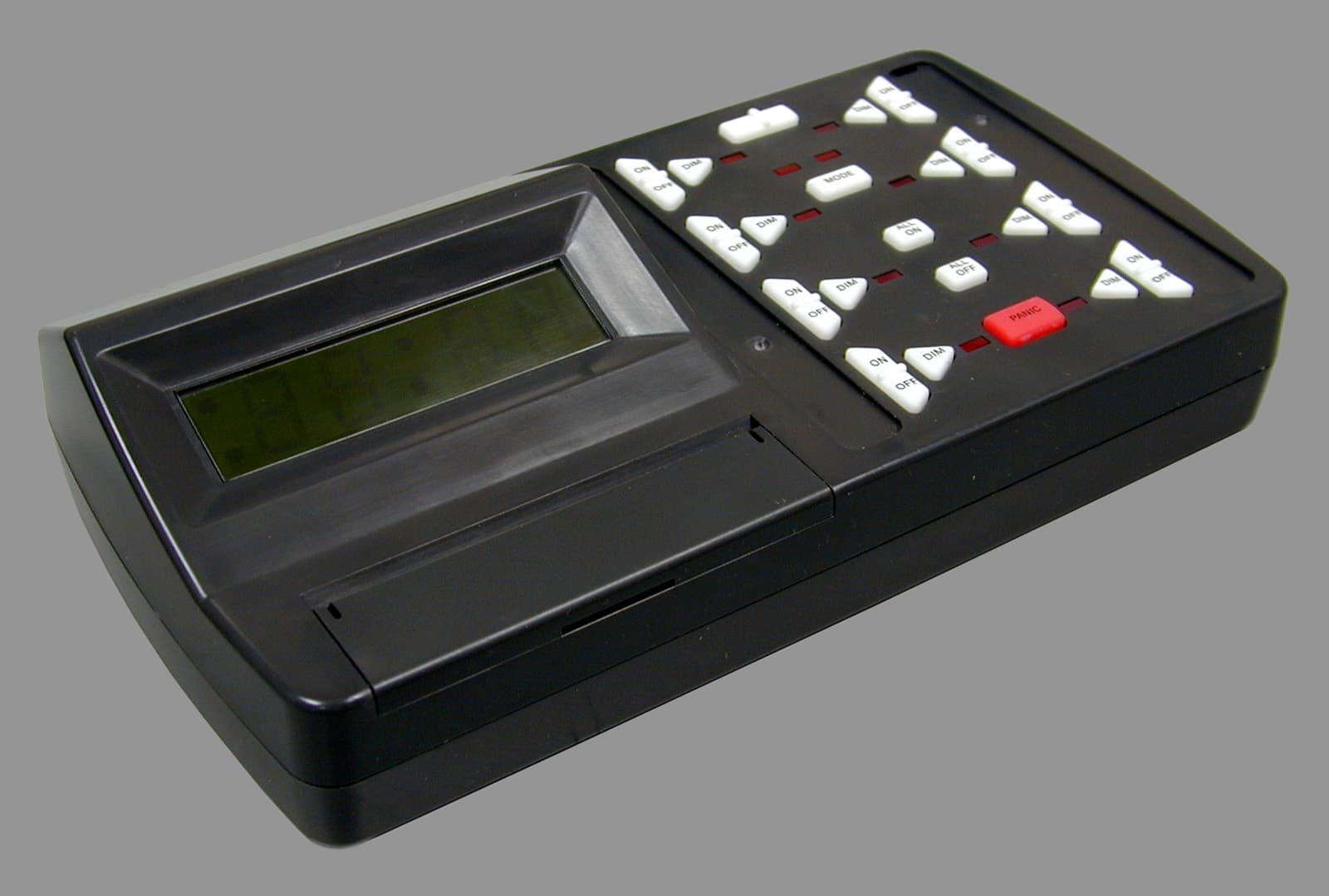
Click to zoom
Application Details
- Equipment Class
- DSC - Part 15 Security/Remote Control Transmitter
- Date of Grant
- Oct 27, 2002
- Application Purpose
- Original Equipment
- Date of Application
- Oct 27, 2002
- Equipment Note
- Wireless Control Panel
- Frequency Range
- 315.00000000 - 315.00000000
- Company
- HeathCo LLC
- Country
- United States
Documents & Files
Document Text
Text extracted from the exhibit documents filed with the FCC. Open a document above to read the original.
Users Manual
DRAFT COPY © 2002 DESA International598-1136-00 Plug-In Control Panel Model SL-6007 Features •Operational range of up to 100 feet. •Controls all Heath ® /Zenith Remote Home™ line of products. •Adds programmable ON/OFF function for up to 16 channels of remote controlled products. •UL/cUL listed power supply. •FCC/IC tested and approved. •12/24 Hour Digital Clock Display. •9V battery backup to prevent program loss. •Flash control on compatible receivers when using the Panic feature. Battery Installation and Battery Backup The SL-6007 is designed for 120VAC operation using the included DC power converter, but has the added feature of an onboard battery backup to prevent program memory loss. To install rechargeable battery: 1. Remove battery cover on rear of hous- ing by sliding cover down. 2.Install rechargeable 9V battery accord- ing to polarity markings. 3. Close battery compartment by revers- ing the previous instructions. Upon power failure, the battery backup will automatically shut down all non-essential functions. The display and keypad will not work. The battery backup will last in excess of 5 hours. When power is restored, the unit will restart the display and set all channels to the OFF position. All programming will be main- tained unless the back up reserve is de- pleted. If the battery is depleted, reprogram- ming of the time and automated functions will again be required. ON O FF DIM GRO UP A B 1 2 MO D E ALL ON ALL O FF PA N I C ON O FF DIM O N O FF DIM ON OFF DIM ON OFF DIM ON O FF DIM ON O FF DIM ON OFF DIM • • • AM A PM 9V Battery Battery Cover DC Power Connector 9 Volt Battery 9 Volt Battery Connector Installing 9 Volt Rechargable Battery and DC Power Connector 2598-1136-00 DRAFT COPY AB ON OFF ON OFF DIM GROUP MODE ALL ON ALL OFF PANIC DIM ON OFF ON OFF DIMDIM ON OFF ON OFF DIMDIM ON OFF ON OFF DIMDIM 1 2 (Dip Switch 4 in DOWN position) (Dip Switch 4 in UP position) 1 2 3 1 2 3 1 2 3 1 2 3 1 2 3 1 2 3 1 2 3 1 2 3 Setting Receiver(s) Dip Switches The Control Panel transmitter has preprogrammed dip switch settings for each channel. In order for the Control Panel to communicate with a receiver, the dip switches on the receiver must correspond with the preprogrammed dip switch settings of the channel you wish to use. Note: There are no dip switches on the Control Panel that re- quire setting. 1. Determine which receiver(s) will be op- erated by which channel. 2. Set receiver(s) dip switches 1, 2, and 3 to match the dip switch settings for the channel you wish to operate the receiver(s). Preprogrammed Dip Switch Settings Channel (Includes ON, OFF, DIM) Setting The Time The following buttons (located under the front cover) are used to set the time: TIME SET, SELECT, and the – (LEFT) and + (RIGHT) arrow buttons. 1. Press the TIME SET button. The hour will highlight. 2.Press the LEFT or RIGHT arrow buttons to adjust the hour (Hint: Holding the arrow button down will scroll through the num- bers. Release the arrow button when the desired hour is displayed). Note: When in 12-hour mode the AM and PM indicators will light indicating which part of the day is currently selected. 3. Press the SELECT button. The minute will highlight. 4.Press the LEFT or RIGHT arrow but- tons to adjust the minute(Hint: Holding the arrow button down will scroll through the numbers. Release the arrow button when the desired hour is displayed). 5. Press the SELECT button. The 12/24-hour mode becomes adjustable. 6.Press the LEFT or RIGHT arrow buttons to toggle between 12-hour and 24-hour display mode. Note: The AM or PM indicator will light when the 12-hour mode is selected. If neither AM nor PM indicator is lit, the 24-hour mode is selected. Note: If a mistake is made, return to the hour, minute, or 12/24-hour indicator at any time by using the SELECT key to scroll to the desired position. When the desired selections are completed, press the TIME SET button. AM PMA –SelectTime Set Program+ – (Left) Arrow Setting the Time AM/PM/24-Hour Indicators Select Button Time Set Button + (Right) Arrow 3598-1136-00 DRAFT COPY AM PMA AB 12 ON OFF ON OFF DIM GROUP MODE ALL ON ALL OFF PANIC DIM ON OFF ON OFF DIMDIM ON OFF ON OFF DIMDIM ON OFF ON OFF DIM DIM –SelectTime Set Program+ AM PMA AB ON OFF ON OFF DIM GROUP MODE ALL ON ALL OFF PANIC DIM ON OFF ON OFF DIMDIM ON OFF ON OFF DIMDIM ON OFF ON OFF DIM DIM –SelectTime Set Program+ 12 Group A Selected Group Selection Group Selection Indicator ON Group B Selected Group Selection Indicator OFF Control Descriptions GROUP: Allows each channel to be used for 2 different groups of receivers (for a total of 16 channels). It also allows for the programming of 2 separate groups of 8 channels, for a total of 16 programmable (ON/OFF) combinations. To choose Group A, press the left side of the switch (the Group Indicator will be on). To choose Group B, press the right side of the switch (the Group Indicator will be off). ALL ON: Turns ON all light fixtures programmed for either Group A or Group B. Each channel LED indicator will light in sequential order as units are turned on. To perform this function, select either Group A or Group B then press ALL ON. If lights are off or dimmed (where applicable) they will be turned on full power. ALL OFF: Turns OFF all light fixtures programmed for either Group A or Group B. Each channel LED indicator will light in sequential order as units are turned on. To perform this function, select either Group A or Group B then press ALL OFF. If lights are on or dimmed (where applicable) they will be turned off. PANIC: Turns ON all light fixtures programmed for either Group A or Group B. Light fixtures within the selected group that have Flash capability will FLASH when this command is received. Each channel LED indicator will alternately light in sequential order. ALL OFF will turn off all channels within the selected group and reset all light fixtures to normal operating mode. Channel ON: Turns ON all light fixtures that are configured to work with a …
Text truncated - open the document above for the full version.
Block Diagram
REF. No: RH-6007-TX BJ4-60WCP07TX Products: 6007 Controller Circuit Block Diagram Power Supply (120VAC/12 VDC converter) 9V Battery charging circuit 5V Regulator ENCODER IC (3kHz) Oscillator (315MHz) Antenna 9V Battery (rechargable) Latch for Transmit Data Keyboard Interface Bus Display Microcontroller Chip 9/27/20026007 Block Diagram.xls
Cover Letter(s)
Barry Quinlan From: "Ruby Dulmage" <[email protected]> To: "Jon D. Curtis - Curtis-Straus" <[email protected]> Sent: Thursday, October 24, 2002 10:50 AM Attach: TCB Response 2W6525 sec. 15.31(e).doc; 390-6007XX-TX1A1NEW.pd f Subject: Anwers - Re: BJ4-60WCP07TX Page 1 of 2 10/28/2002 Hi Jon: In response to your issues: 1. Attached is a revised label without the FCC logo. 2. The label material - polyester coated with permanent adhesive on the back. 3. Attached is the data for 15.31(e). I trust this information will enable you to grant this approval. Thanks, Ruby Ruby Dulmage Submissions Specialist Nemko Canada Inc. 303 River Road, R.R. 5 Ottawa, ON K1V 1H2 Tel: 613-737-9680 ext 232 Fax: 613-737-9691 Email: [email protected] > >>----- Original Message ----- > >>From: "Jon Curtis" <jdc@curtis -straus.com> > >>To: <[email protected]> > >>Sent: Wednesday, October 23, 2002 3:16 PM > >>Subject: BJ4-60WCP07TX > >> > >> > >>> Ruby, > >>> > >>> Thanks for your business. Please address the following issues so that > >>> we may grant your most recent submission. > >>> > >>> 1. The FCC is no longer allowing the logo to be used on certified > >>> products. It is only for products subject to declaration of conformity. > >>> Please submit a new label format without the FCC logo. > >>> > >>> 2. Please tell us the material of the label and the nature of the > >>> adhesive (temporary or permanent). > >>> > >>> 3. Please provide data responsive to 15.31(e) power line variations > >>> requirements. > >>> > >>> -- > >>> Jon D. Curtis, P.E. > >>> > >>> Director of Engineering > >>> Curtis-Straus LLC NRTL TCB > >>> > >>> One Stop Laboratory for NEBS, EMC, > >>> Product Safety, and Telecom Testing. > >>> 527 Great Road > >>> Littleton, MA 01460 USA > >>> Voice 978-486-8880 Fax 978-486-8828 > >>> email: jcurtis@curtis -straus.com > >>> WWW.CURTIS -STRAUS.COM > >>> > >>> > >>> > >> > >> > > > Page 2 of 2 10/28/2002
ID Label/Location Info
DRAFT COPY AB ON OFF ON OFF DIM GROUP MODE ALL ON ALL OFF PANIC DIM ON OFF ON OFF DIMDIM ON OFF ON OFF DIMDIM ON OFF ON OFF DIMDIM 12 (Dip Switch 4 in DOWN position) (Dip Switch 4 in UP position) 1 2 3 1 2 3 1 2 3 1 2 3 1 2 3 1 2 3 1 2 3 1 2 3 For Indoor Use Only This device complies with part 15 of the FCC Rules. Operation is subject to the following two conditions: (1) this device may not cause harmful interference, and (2) this device must accept any interference received, including interference that may cause un- desired operation. Made in China 390-6007XX-TX1A DESA International, Bowling Green, KY INPUT: 12V DC Model RH-6007-TX FCC ID: BJ4-60WCP07TX IC: 3984A-6007 Preprogrammed Dip Switch Settings
Operational Description
DESA International 9/27/2002 Confidential 6014-TX Wireless Wall Switch Wireless Control Panel Model Number: 6007-TX General Description: The 6007-TX Wireless Control panel is a base transmitter unit used for remotely controlling multiple receivers (up to 16) from a single location. The device is capable of transmitting four separate commands, which are used to turn room lights ON, OFF or to several different levels of DIM. The fourth command is a FLASH command that can be used to put the lights in a flashing mode. The FLASH command is associated with the panic button on the controller. The housing and pushbuttons are made from non-metallic materials in order to improve transmission range and omni directionality. The electrical circuitry is comprised of a 12VDC power supply, a microprocessor unit, 2 soft touch keyboards that electrically connect traces on the board when pushed, two data storage latches, a LED type clock display, a CMOS 12-bit encoder IC, a 315 MHz RF oscillator circuit, and complementary passive components. The circuitry is soldered to a double-sided, 94V-0 rated printed circuit board. The circuit is powered by a 12VDC power converter from a standard 120VAC, 60 Hz wall outlet and also has a battery backup system which is run from a 9 Volt rechargeable battery. Specifications: • Input: 12VDC • Circuit voltage: +5.0 volts DC. A common regulator and power supply circuit regulate battery output. • Radio Frequency: 315 MHz • User-selectable address codes: 8, unused in current devices. 16 codes are selected from the keypad, by pushing the appropriate buttons.
Schematics
keypad_circuit_B6006/7 Remote Keypad W. Raper Custom Sept. 26, 2002 0001 B 11 Title:Designed by:Checked by:Approved by: Size DateDocument N Revision Sheet of 0 0 11 22 33 44 55 66 77 88 99 1010 1111 1212 1313 1414 1515 1616 1717 1818 1919 A A B B C C D D E E F F G G H H I I J J K K L L M M N N O O /MCLR/Vpp RA0/AN0RA1/AN1RA2/AN2 RA3/AN3/Vref RA4/T0CK1 RA5//SS/AN4 RE0//RD/AN5 RE1//WR/AN6 RE2//CS/AN7 Vdd Vss OSC1/CLKIN OSC2/CLKOUT RC0/T1OSO/T1CKI RC1/T1OSI/CCP2 RC2/CCP1 RC3/SCK/SCL RD0/PSP0 RD1/PSP1 RD2/PSP2RD3/PSP3 RC4/SDI/SDA RC5/SDO RC6/TX/CKRC7/RX/DT RD4/PSP4 RD5/PSP5 RD6/PSP6 RD7/PSP7 Vss1 Vdd1 RB0/INT RB1RB2RB3RB4RB5RB6RB7 U4 40pinDIPPIC16C65B HT-12E Bus Bus V1 9V AC InputWall adapterprovides DC 12V U2 LEDDISPLAY AMPM_GND AM_IND PM_IND SEGMENTA GND_L2 GND_L1 SEGMENTE SEGMENTD COLON_GND COLON_BTM COLON_TOP SEGMENTC GND_L3 GND_L4 SEGMENTG SEGMENTB SEGMENTF XLED_GND XLED_PWR OFF1DIM1ON2 Key = Space OFF2 Key = Space DIM2 Key = Space ON3 Key = Space OFF3 Key = Space DIM3 Key = Space ON4 Key = Space OFF4 Key = Space DIM4 Key = Space UP Key = Space ENTER Key = Space DOWN Key = Space ALL_OFF Key = Space ALL_ON Key = Space PROGRAM Key = Space MODE Key = Space PANIC Key = Space TIME_SET Key = Space ON5 Key = Space OFF5 Key = Space DIM5 Key = Space ON6 Key = Space OFF6 Key = Space DIM6 Key = Space ON7 Key = Space OFF7 Key = Space DIM7 Key = Space ON8 Key = Space OFF8 Key = Space DIM8 Key = Space R2 220Ohm_5% R3 220Ohm_5% R4 220Ohm_5% R5 220Ohm_5% R6 220Ohm_5% Q1 2N3904 Q2 2N3904 Q3 2N3904 Q4 2N3904 R11 220Ohm_5% U1 NET_18 J21HDR2X3 1D 3 2D 4 3D 7 4D 8 5D 13 6D 14 7D 17 8D 18 ~OC 1 ENG 11 1Q 2 2Q 5 3Q 6 4Q 9 5Q 12 6Q 15 7Q 16 8Q 19 U7 74LS373N LED3 LED4 LED5 LED6 LED7 LED8 LED9 LED10 1D 3 2D 4 3D 7 4D 8 5D 13 6D 14 7D 17 8D 18 ~OC 1 ENG 11 1Q 2 2Q 5 3Q 6 4Q 9 5Q 12 6Q 15 7Q 16 8Q 19 U9 74LS373N MODE1 MODE2 R16 220Ohm_5% R17 220Ohm_5% R1 2.2kOhm_5% R7 2.2kOhm_5% R8 2.2kOhm_5% R10 2.2kOhm_5% C1 33pF C2 33pF C3 27pF C4 27pF R15 100kOhm_1% R27 220Ohm_5% R28 220Ohm_5% R29 220Ohm_5% R30 220Ohm_5% R31 220Ohm_5% R33 220Ohm_5% R32 220Ohm_5% X1 HC-49/US_7MHz X2 R38-32.768kHz R25 6.8kOhm_5% R35 4.7kOhm_5% R36 1.0kOhm_5% D1 1N4003 D21N4003 Vreg U3 MC7805CT IN OUT C5 220uF 12V VDD BatteryBackup,Rechargable 5V VCC C6 10nF C7 10nF C8 22uF C9 10nF Q5 2N3904 R34 10kOhm_5% Must heatsink 7805 8MHz RD0RD1RD2RD3RD4RD5RD6RD7 RD0 RD1 RD2 RD3 RD4 RD5 5V Vee Q6 2N3906 Q7 2N3904 R46 10kOhm_5% 5V Vee Use Vee Power Source RD0RD1RD2RD3RD4RD5RD6RD7 32.768kHz R13 330Ohm_5% R38 330Ohm_5% R39 330Ohm_5% R40 330Ohm_5% R41 330Ohm_5% R42 330Ohm_5% R43 330Ohm_5% R44 330Ohm_5% RD1RD2RD3RD4RD5RD6RD7 L1 1.5uH TC1 45% 2-5pF C10 5.6pF C11 3.0pF C12 4.7pF Q8 C1923Y C13 47pF C14 20pF C15 20pF 5V Vee R51 100kOhm_5% LED1 R52 220Ohm_5% R53 270Ohm_5% R45 10kOhm_5% R49 56kOhm_5% R48 27kOhm_5% R50 1.0MOhm_5% DEVICE_GROUP_A Key = Space DEVICE_GROUP_B Key = Space Rev A. Eliminate U8, R12, R18 - R24. Release to production. R9 470Ohm_5% R26 1.0kOhm_5% R14 1.0kOhm_5% R37 1.0kOhm_5% R47 220Ohm_5% Rev B. R4 8 was 22 Ohm; R9, R14, R26, R37 was 220 Ohm.
Test Report
Master:PT15-Sub-C-15231 Date: November 12, 2001 Test Report:2W06525 Applicant:DESA International 2901 Industrial Drive Bowling Green, KY 42102 Equipment Under Test:6007TX (EUT) FCC ID:BJ4-60WCP07TX In Accordance With:FCC Part 15, Subpart C, 15.231 Tested By:Nemko Canada Inc. 303 River Road, R.R. 5 Ottawa, Ontario K1V 1H2 Authorized By: G. Westwell, Wireless Technologist Date:17 October 2002 Total Number of Pages:28 Nemko Canada Inc.FCC PART 15, SUBPART C, 15.231 PROJECT NO.:2W06535 EQUIPMENT: 6007TX Page 2 of 28 Table of Contents Section 1. Summary of Test Results......................................................................................3 Section 2. Equipment Under Test.........................................................................................5 Section 3. Transmission Requirements...............................................................................15 Section 4. Radiated Emissions.............................................................................................17 Section 5. Occupied Bandwidth..........................................................................................21 Section 6. Powerline Conducted Emissions........................................................................23 Section 7. Block Diagrams...................................................................................................27 Section 8. Test Equipment List...........................................................................................28 Nemko Canada Inc.FCC PART 15, SUBPART C, 15.231 PROJECT NO.:2W06535 EQUIPMENT: 6007TX Page 3 of 28 Section 1.Summary of Test Results General All measurements are traceable to national standards. These tests were conducted on a sample of the equipment for the purpose of demonstrating compliance with Part 15, Subpart C. All tests were conducted using measurement procedure ANSI C63.4-1992. Radiated emissions are made on an open area test site. A description of the test facility is on file with the FCC. THIS TEST REPORT RELATES ONLY TO THE ITEM(S) TESTED. THE FOLLOWING DEVIATIONS FROM, ADDITIONS TO, OR EXCLUSIONS FROM THE TEST SPECIFICATIONS HAVE BEEN MADE. NONE See “ Summary of Test Data”. TESTED BY: ______________________________DATE: 17 October 2002 Kevin Carr, EMC Specialist Nemko Canada Inc. authorizes the above named company to reproduce this report provided it is reproduced in its entirety and for use by the company’s employees only. Any use which a third party makes of this report, or any reliance on or decisions to be made based on it, are the responsibility of such third parties. Nemko Canada Inc. accepts no responsibility for damages, if any, suffered by any third party as a result of decisions made or actions based on this report. This report applies only to the items tested. Nemko Canada Inc.FCC PART 15, SUBPART C, 15.231 PROJECT NO.:2W06535 EQUIPMENT: 6007TX Page 4 of 28 Summary Of Test Data Name of TestPara. NumberResults Transmission Requirements15.231(a)Complied Radiated Emissions15.231(b)Complied Occupied Bandwidth15.231(c)Complied Frequency Tolerance15.231(d)N/A Periodic Alternate Field Strength Requirements15.231(e)N/A Powerline Conducted Emissions15.207Complied Test Conditions: IndoorTemperature:21?C Humidity:40% OutdoorTemperature:17?C Humidity:65% Please note that fresh batteries were used for testing. Nemko Canada Inc.FCC PART 15, SUBPART C, 15.231 PROJECT NO.:2W06535 EQUIPMENT: 6007TX Page 5 of 28 Section 2.Equipment Under Test General Equipment Information Manufacturer: Desa International Model No.: 6007TX Serial No.: N/A Date Received In Laboratory: 10 Oct. 2002 Nemko Identification No.: 2 Frequency Range (or fixed frequency): 315MHz, fixed RF Power in Watts: 0.00000105W Field Strength (distance): 74.4dBuV Occupied Bandwidth (99% BW): 147.5kHz Type of Modulation: PCM Emission Designator: 147k5L1D Primary Power: 120VAC, 60Hz Duty Cycle Calculations: 20 Log {5X((4X0.288)+(9X0.592))/100}=-9.8dB Nemko Canada Inc.FCC PART 15, SUBPART C, 15.231 PROJECT NO.:2W06535 EQUIPMENT: 6007TX Page 6 of 28 Duty Cycle Calculations Plots: Nemko Canada Inc.FCC PART 15, SUBPART C, 15.231 PROJECT NO.:2W06535 EQUIPMENT: 6007TX Page 7 of 28 Nemko Canada Inc.FCC PART 15, SUBPART C, 15.231 PROJECT NO.:2W06535 EQUIPMENT: 6007TX Page 8 of 28 Nemko Canada Inc.FCC PART 15, SUBPART C, 15.231 PROJECT NO.:2W06535 EQUIPMENT: 6007TX Page 9 of 28 Nemko Canada Inc.FCC PART 15, SUBPART C, 15.231 PROJECT NO.:2W06535 EQUIPMENT: 6007TX Page 10 of 28 Nemko Canada Inc.FCC PART 15, SUBPART C, 15.231 PROJECT NO.:2W06535 EQUIPMENT: 6007TX Page 11 of 28 Nemko Canada Inc.FCC PART 15, SUBPART C, 15.231 PROJECT NO.:2W06535 EQUIPMENT: 6007TX Page 12 of 28 Nemko Canada Inc.FCC PART 15, SUBPART C, 15.231 PROJECT NO.:2W06535 EQUIPMENT: 6007TX Page 13 of 28 Nemko Canada Inc.FCC PART 15, SUBPART C, 15.231 PROJECT NO.:2W06535 EQUIPMENT: 6007TX Page 14 of 28 99% Occupied Bandwidth Nemko Canada Inc.FCC PART 15, SUBPART C, 15.231 PROJECT NO.:2W06535 EQUIPMENT: 6007TX Page 15 of 28 Section 3.Transmission Requirements Para. No.: 15.231(a) Test Performed By: Kevin CarrDate of Test: 10 Oct. 2002 Minimum Standard:15.231(a) Continuous transmissions such as voice, video or data transmissions are not permitted. 15.231(a)(1) A manually operated transmitter shall employ a switch that will automatically deactivate the transmitter within not more than 5 seconds after being released. 15.231(a)(2) A transmitter activated automatically shall cease transmission within 5 seconds of activation. 15.231(a)(3) Periodic transmissions at regular pre-determined intervals are not permitted. However polling or supervisory transmissions to determine system integrity of transmitters used in security or safety applications are allowed if the periodic rate of transmission does not exceed one transmission of not more than one second duration per hour for each transmitter. 15.231(a)(4) Intentional radiators which are employed for radio control purposes during emergencies inv…
Text truncated - open the document above for the full version.
Test Report
2W6525 Sec. 15.31(e) Power Line Variations Power Line Fundamental, Amplitude Variations wrt 115VAC, 60Hz Level 85% (dB) Vert. 0.4 Horz. -0.1 115% Vert. -0.7 Horz. 0.4
Test Setup Photos
Nemko Canada Inc.FCC PART 15, SUBPART C, 15.231 PROJECT NO.:2W06535 EQUIPMENT: 6007TX Page 26 of 28 Setup Photos Front Side Nemko Canada Inc.FCC PART 15, SUBPART C, 15.231 PROJECT NO.:2W06535 EQUIPMENT: 6007TX Page 20 of 28 OATS Set-up Photos Front Rear
Contact Information
Applicant
Jeff Bessinger(Associate Regulatory Engineer)
Test Firm
Nemko Canada Inc.Stuart Beck
Technical Specifications
| # | Rule Parts | Frequency Range | Power Output |
|---|---|---|---|
| 1 | 15.231 | 315 MHz - 315 MHz | - |
Other Applications from HeathCo LLC

BJ4-9309
Apr 01, 2020Connected LED video security motion light
Equipment Class
DTS - Digital Transmission System
BJ4-9000
Mar 25, 2020Connected Wired Decorative Motion Light
Equipment Class
DTS - Digital Transmission System
BJ4-WLTRX9600
Jan 05, 2020Video Doorbell with 2.4GHz wifi
Equipment Class
DTS - Digital Transmission System
BJ4-WLTX204
Jul 19, 2015Wireless Doorbell extender Kit
Equipment Class
DSC - Part 15 Security/Remote Control Transmitter
BJ4-WLTX208
Jul 06, 2015Wireless Door Chime Transmitter
Equipment Class
DSC - Part 15 Security/Remote Control Transmitter