BJ4-60WRC02TX6002TX Remote Control Transmitter
HeathCo LLC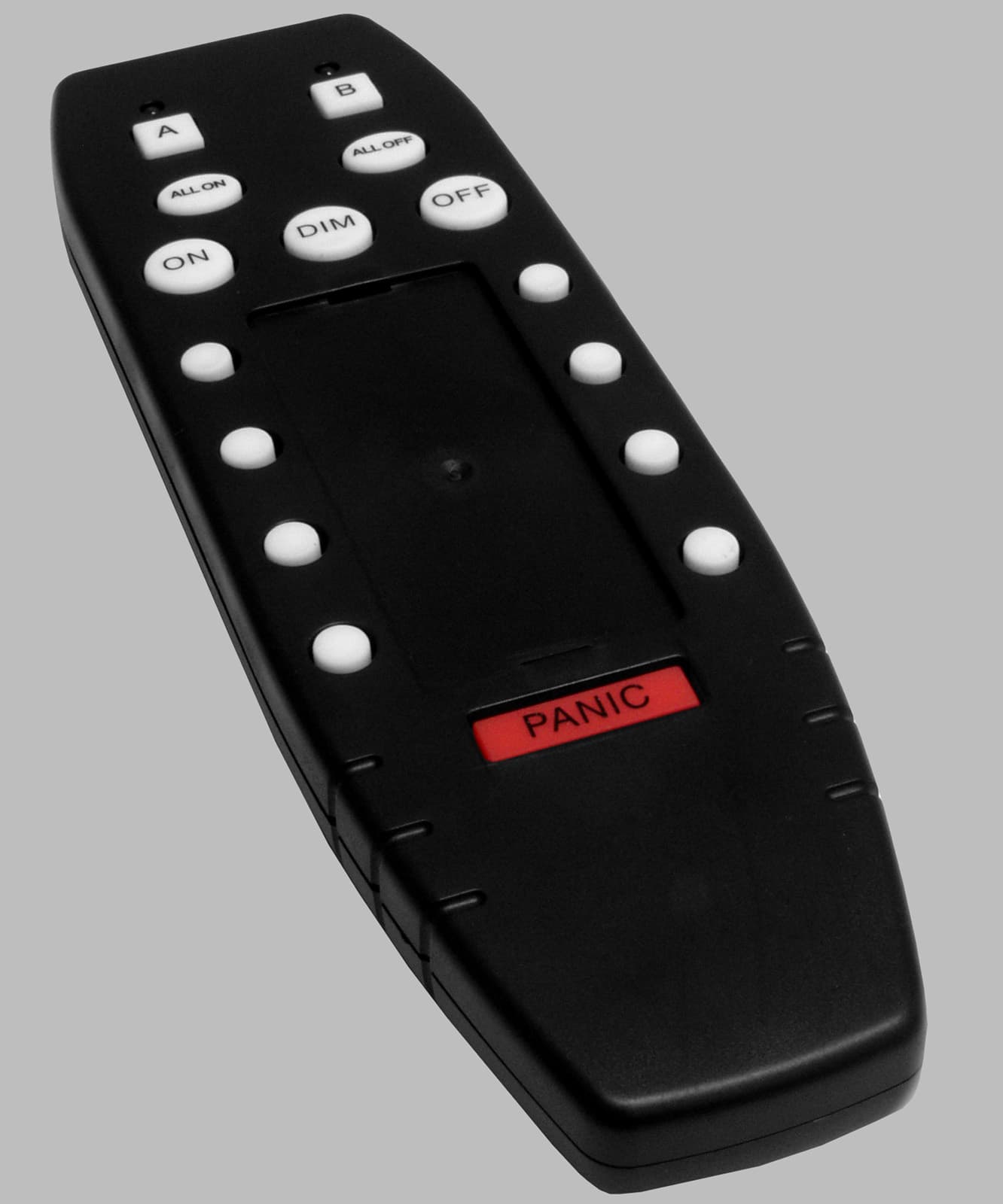
Click to zoom
Application Details
- Equipment Class
- DSC - Part 15 Security/Remote Control Transmitter
- Date of Grant
- Jul 01, 2003
- Application Purpose
- Original Equipment
- Date of Application
- Jul 01, 2003
- Equipment Note
- 6002TX Remote Control Transmitter
- Frequency Range
- 315.00000000 - 315.00000000
- Company
- HeathCo LLC
- Country
- United States
Documents & Files
Document Text
Text extracted from the exhibit documents filed with the FCC. Open a document above to read the original.
Users Manual
DRAFT COPY © 2003 DESA Specialty Products™598-1145-00 Multi-Channel Remote Control Features •Operational range of up to 100 feet. •Controls all Heath ® /Zenith Remote Home™ products. •FCC/IC tested and approved. •Flash control on compatible receivers when using the Panic feature. Battery Cover Two AAA Batteries (Not Included) Installing 2-AAA Batteries A L L O N A L L O F F O FF DIM PA N IC A B ON GROUP (Dip Switch 4 in DOWN position) (Dip Switch 4 in UP position) 1 2 3 1 2 3 1 2 3 1 2 3 1 2 3 1 2 3 1 2 3 1 2 3 AB Setting Receiver(s) Dip Switches The Control Panel transmitter has preprogrammed dip switch settings for each channel. In order for the Control Panel to communicate with a receiver, the dip switches on the receiver must correspond with the preprogrammed dip switch settings of the channel you wish to use. Note: There are no dip switches on the Control Panel that require setting. 1. Determine which receiver(s) will be operated by which channel. 2. Set receiver(s) dip switches 1, 2, and 3 to match the dip switch settings for the channel you wish to operate the receiver(s). 3. Determine whether the receiver(s) will be in Group A or B. 4. Set dip switch 4 on the receiver to the same setting as Group A or B. Preprogrammed Dip Switch Settings for Remote Control (Included on Back of Product as a Reference) Battery Installation The Multi-Channel Remote Control is de- signed for 3 Volt operation: 1. Remove battery cover on rear of hous- ing by pushing clip and lifting up. 2.Install 2-AAA batteries (not included) according to polarity markings. 2598-1145-00 DRAFT COPY Control Descriptions A or B GROUP: Allows each channel to be used for 2 dif- ferent groups of receivers (for a total of 16 channels). To choose Group A, press the “A” button (the Group “A” in- dicator will be on). To choose Group B, press the “B” but- ton (the Group “B” indicator will be on). Label Channels: Remove clear plastic film from chan- nel label guide by placing two fingers on the plastic and “pinching” the plastic. Re- move card. Use the decals (included) or write on the card to label each channel. Re- place card and plastic film. ALL ON: Turns ON all light fixtures programmed for ei- ther Group A or Group B. Either Group A or Group B LED indicator will light as units are turned on. To perform this function, select either Group A or Group B then press ALL ON. If lights are off or dimmed (where applicable) they will be turned on full power. ALL OFF: Turns OFF all light fixtures programmed for either Group A or Group B. Either Group A or Group B LED indicator will light as units are turned off. To perform this function, select either Group A or Group B then press ALL OFF. If lights are on or dimmed (where applicable) they will be turned off. PANIC: Turns ON all light fixtures programmed for either Group A or Group B. Light fixtures within the selected group that have Flash capability will FLASH when this command is received. Either Group A or Group B LED indicator will light. ALL OFF will turn off all channels within the selected group and reset all light fixtures to normal operating mode. Channel ON: Turns ON all light fixtures that are configured to work with a particular channel. To perform this function, press the ON button after selecting the channel number desired (between 1 and 8). When ON is pressed, the A or B LED will momentarily light. Channel OFF: Turns OFF all light fixtures that are configured to work with a particular channel. To perform this function, press the OFF button after selecting the channel number desired (between 1 and 8). When OFF is pressed, the A or B LED will momentarily light. ON ALL ONALL OFF DIM PANIC AB OFF Channel Label Guide ALL OFF ALL ON Group Selection Buttons Group Selection LED Indicators Group Selection 3598-1145-00 DRAFT COPY Channel DIM: Dims all light fixtures that are equipped with the dimming feature that are configured to work with a particular channel. To perform this function, press the DIM button located by the channel number desired (between 1 and 8). Pressing DIM repeatedly will toggle thru the different dim levels if the light fixture is capable of more than one level of dim. Each time the DIM button is pressed, the channel LED will momentarily light. The receiver saves the last dim setting used. To recall the last dim setting, press the DIM channel once. Note: The receiver must be capable of dimming for the DIM button to work properly. Specifications Range .......................................................................... Up to 100 feet (30.5 m) Rated Voltage (2-AAA Batteries) .......................................................... 3 VDC POSSIBLE CAUSE 1. Batteries installed incor- rectly. 2. Batteries are dead. 1. Dip switch settings on re- ceiver do not match con- troller. 2. Wrong group or channel is selected. 3. Signals from controller are being blocked, or transmit- ter is out of range. 4. Batteries are weak. Troubleshooting Guide SYMPTOM Remote con- trol does not come on. Remote con- trol will not op- erate receiver. Technical Service (Do Not Send Products) If you experience a problem, follow this guide. You may also want to visit our Web site at: www.desatech.com. If the problem persists, call* for assistance at 1-800- 858-8501, 7:30 AM to 4:30 PM CST (M-F). You may also write* to: DESA Specialty Products™ P.O. Box 90004, Bowling Green, KY 42102-9004 ATTN: Technical Service Specialty Products * If contacting Technical Service, please have the following information avail- able: Model Number, Date of Purchase, and Place of Purchase. No Service Parts Available for this Product SOLUTION 1. Install batteries according to polarity markings inside remote control. 2. Replace batteries. 1. Check dip switch settings on receiver. 2. Verify correct group and channel are selected. 3.Check for metal objects that could block the signal, or reposition the transmitter. 4. Replace batteries. 4598-1145-00 DRAFT COPY TWO YEAR LIMITED WARRANTY This is a “Limited War…
Text truncated - open the document above for the full version.
Block Diagram
REF. No: 6002 TX 3V Battery Power Circuit power control switch (transistor) SAW (315MHz) Micro Controller Transmitter Circuit (315 MHz) Transmitter Circuit Block Diagram 6/12/2003Block Diagram of 6002-TX.xls Antenna (Coiled Wire, Internal) 6/12/2003Block Diagram of 6002-TX.xls
Cover Letter(s)
Response to TCB Findings 1. The label exhibit file "390-6002XX-TX1A.pdf" has an incorrect grantee code on it. Please supply corrected sample as well as label location pictures with better resolution Response: The exhibit corrected. See new label exhibit and label location documents. 2. Please specify the label material. Response: The label material is (adhesive backed paper with a polyester coating)
ID Label/Location Info
DRAFT COPY FCC ID: BJ4-60WRC02TX CANADA: 3984A-6002TX This device complies with part 15 of the FCC Rules. Operation is subject to the following conditions: (1) this device may not cause harmful interference, and (2) this device must accept any interference received, including interference that may cause undesired operation. DESA Specialty Products™, Bowling Green, KY 6002-TXMade in China 390-6002XX-TX1A
ID Label/Location Info
Page 1 of 1 7/2/03file://\\Certification2\d\TCB\Trans%20applications%20(in%20process)\BJ4-60WRC02TX\FC...
Operational Description
6002 REMOTE CONTROL TX Heath®/Zenith Model number: XX-6002 (XX prefix changes for different brands) FCC Model designation 6002TX FCC ID#: BJ4-60WRC02TX IC#: Canada: 3984A-6002TX 6002 Description Two AAA batteries power this unit. The input power is connected to the micro controller, which switches power on and off to the remainder of the circuit. When a key is pressed, the micro controller switches power on to the transmitter section. The micro controller also supplies a digital code to the RF section of the circuit, which is transmitted by the RF circuit. The dipswitch controls the coding of the digital code. The A or B control selection, the number pressed (1 through 8), and the command button pressed (ON, OFF, or DIM) also determine the code. The ALL ON, ALL OFF, and PANIC selection transmits to all the codes in order to issue that command to each receiver device in use. This process takes about 4.8 seconds. Two LEDS indicate when the transmitter is active and which control selection (A or B) is in use. The transmitter does not transmit when the numbers 1 through 8, or the A or B button is pressed. These are configuration buttons. The output of the encoder chip goes through the oscillator/modulator stage. A SAW locks the frequency, which is tuned for 315M Hz. The encoded signal is then sent through the “helical” antenna mounted on the front of the PCB and the RF output is transmitted into the air.
Schematics
12 1 RA2/AIN2/VREF 16 RA7/OSC1/CLKI 11 RB5 8 RB2 14 VDD 2 RA3/AIN3/CMP1 4 RA5/M C L R /THV 17 RA0/AIN0 18 RA1/AIN1 6 RB0/INT 7 RB1 9 RB3 10 RB4 12 RB6 5 VSS 13 RB7 3 RA4/T0CKI/CMP1 15 RA6/OSC2/CLKO
Test Report
Master:PT15-Sub-C-15231 Date: November 12, 2001 Test Report: 3W07236 Applicant: Desa International PO Box 90004 2901 Industrial Ave Bowling Green KY 42102 Equipment Under Test: 6002TX Remote Control Transmitter (EUT) FCC ID: BJ4-60WRC02TX In Accordance With: FCC Part 15, Subpart C, 15.231 Tested By: Nemko Canada Inc. 303 River Road, R.R. 5 Ottawa, Ontario K1V 1H Authorized By: Kevin Carr, EMC Specialist Date: 27 June 2003 Total Number of Pages: 17 Nemko Canada Inc. FCC PART 15, SUBPART C, 15.231 PROJECT NO.: 3W07236 EQUIPMENT: 6002TX Page 2 of 17 Table of Contents Section 1. Summary of Test Results ...................................................................................... 3 Section 2. Equipment Under Test .......................................................................................... 5 Section 3. Transmission Requirements ................................................................................. 9 Section 4. Radiated Emissions .............................................................................................. 11 Section 5. Occupied Bandwidth ........................................................................................... 14 Section 6. Block Diagrams .................................................................................................... 16 Section 7. Test Equipment List ............................................................................................. 17 Nemko Canada Inc. FCC PART 15, SUBPART C, 15.231 PROJECT NO.: 3W07236 EQUIPMENT: 6002TX Page 3 of 17 Section 1. Summary of Test Results General All measurements are traceable to national standards. These tests were conducted on a sample of the equipment for the purpose of demonstrating compliance with Part 15, Subpart C. All tests were conducted using measurement procedure ANSI C63.4-1992. Radiated emissions are made on an open area test site. A description of the test facility is on file with the FCC. THIS TEST REPORT RELATES ONLY TO THE ITEM(S) TESTED. THE FOLLOWING DEVIATIONS FROM, ADDITIONS TO, OR EXCLUSIONS FROM THE TEST SPECIFICATIONS HAVE BEEN MADE. See “ Summary of Test Data”. TESTED BY: _______________________________ DATE: 27 June 2003 Glen Westwell, Wireless Technologist Nemko Canada Inc. authorizes the above named company to reproduce this report provided it is reproduced in its entirety and for use by the company’s employees only. Any use which a third party makes of this report, or any reliance on or decisions to be made based on it, are the responsibility of such third parties. Nemko Canada Inc. accepts no responsibility for damages, if any, suffered by any third party as a result of decisions made or actions based on this report. This report applies only to the items tested. Nemko Canada Inc. FCC PART 15, SUBPART C, 15.231 PROJECT NO.: 3W07236 EQUIPMENT: 6002TX Page 4 of 17 Summary Of Test Data Name of Test Para. Number Results Transmission Requirements 15.231(a) Complies Radiated Emissions 15.231(b) Complies Occupied Bandwidth 15.231(c) Complies Frequency Tolerance 15.231(d) NA Periodic Alternate Field Strength Requirements 15.231(e) NA Powerline Conducted Emissions 15.207 NA Note: This device is powered by two 1.5Vdc AAA cells. Test Conditions: Indoor Temperature: 23°C Humidity: 51% Outdoor Temperature: 30°C Humidity: 51% Nemko Canada Inc. FCC PART 15, SUBPART C, 15.231 PROJECT NO.: 3W07236 EQUIPMENT: 6002TX Page 5 of 17 Section 2. Equipment Under Test General Equipment Information Manufacturer: Desa International Equipment 315 MHz Wireless Remote Control Transmitter Model No.: 6002TX Serial No.: None Date Received In Laboratory: 17 June 2003 Nemko Identification No.: #2 Transmit Frequency: 315MHz Fixed Modulation: Pulse Carrier On Off (PCM) Emission Designator: 19K8L1D Nemko Canada Inc. FCC PART 15, SUBPART C, 15.231 PROJECT NO.: 3W07236 EQUIPMENT: 6002TX Page 6 of 17 Nemko Canada Inc. FCC PART 15, SUBPART C, 15.231 PROJECT NO.: 3W07236 EQUIPMENT: 6002TX Page 7 of 17 Nemko Canada Inc. FCC PART 15, SUBPART C, 15.231 PROJECT NO.: 3W07236 EQUIPMENT: 6002TX Page 8 of 17 Nemko Canada Inc. FCC PART 15, SUBPART C, 15.231 PROJECT NO.: 3W07236 EQUIPMENT: 6002TX Page 9 of 17 Section 3. Transmission Requirements Para. No.: 15.231(a) Test Performed By: Glen Westwell & Desa S.P. Date of Test: 20 June 2003 Minimum Standard: 15.231(a) Continuous transmissions such as voice, video or data transmissions are not permitted. 15.231(a)(1) A manually operated transmitter shall employ a switch that will automatically deactivate the transmitter within not more than 5 seconds after being released. 15.231(a)(2) A transmitter activated automatically shall cease transmission within 5 seconds of activation. 15.231(a)(3) Periodic transmissions at regular pre-determined intervals are not permitted. However polling or supervisory transmissions to determine system integrity of transmitters used in security or safety applications are allowed if the periodic rate of transmission does not exceed one transmission of not more than one second duration per hour for each transmitter. 15.231(a)(4) Intentional radiators which are employed for radio control purposes during emergencies involving fire, security, and safety of life, when activated to signal an alarm, may operate during the pendency of the alarm. Test Results: Complies Test Data: Compliance was determined by verification of technical specifications and a functional test on the equipment. Nemko Canada Inc. FCC PART 15, SUBPART C, 15.231 PROJECT NO.: 3W07236 EQUIPMENT: 6002TX Page 10 of 17 Rationale for Compliance with Transmission Requirements 15.231(a)(1) : The transmitter is deactivated 4.5 seconds upon releasing the push button switch (worst case, see plot below). 15.231(a)(2) : No automatic activation. 15.231(a)(3) : No periodic, polling, or supervision transmissions. 15.231(a)(4) : NA Nemko Canada Inc. FCC PART 15, SUBPART C, 15.231 PROJECT NO.: 3W07236 EQUIPMENT: 6002TX Page 11 of 17 Section 4. Radiated Emissions Para. N…
Text truncated - open the document above for the full version.
Test Setup Photos
OATS Set Up
Contact Information
Applicant
Jeff Bessinger(Associate Regulatory Engineer)
Test Firm
Nemko Canada Inc.Stuart Beck
Technical Specifications
| # | Rule Parts | Frequency Range | Power Output |
|---|---|---|---|
| 1 | 15.231 | 315 MHz - 315 MHz | - |
Other Applications from HeathCo LLC

BJ4-9309
Apr 01, 2020Connected LED video security motion light
Equipment Class
DTS - Digital Transmission System
BJ4-9000
Mar 25, 2020Connected Wired Decorative Motion Light
Equipment Class
DTS - Digital Transmission System
BJ4-WLTRX9600
Jan 05, 2020Video Doorbell with 2.4GHz wifi
Equipment Class
DTS - Digital Transmission System
BJ4-WLTX204
Jul 19, 2015Wireless Doorbell extender Kit
Equipment Class
DSC - Part 15 Security/Remote Control Transmitter
BJ4-WLTX208
Jul 06, 2015Wireless Door Chime Transmitter
Equipment Class
DSC - Part 15 Security/Remote Control Transmitter