BJ4-60WRC16TX6016TX Remote Control
HeathCo LLC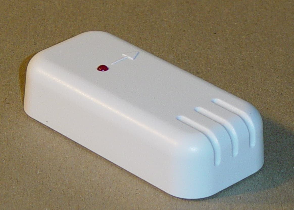
Click to zoom
Application Details
- Equipment Class
- DSC - Part 15 Security/Remote Control Transmitter
- Date of Grant
- Aug 25, 2003
- Application Purpose
- Original Equipment
- Date of Application
- Aug 25, 2003
- Equipment Note
- 6016TX Remote Control
- Frequency Range
- 315.00000000 - 315.00000000
- Company
- HeathCo LLC
- Country
- United States
Documents & Files
Document Text
Text extracted from the exhibit documents filed with the FCC. Open a document above to read the original.
Users Manual
FEATURES •Products are UL/cUL and/or FCC/IC tested and approved. •Operational range of up to 100 feet. Heath ® /Zenith wireless lighting controls are designed to work together. Simply determine which transmitter(s) you would like to have control which receiver(s) and set the code setting to match. •Transmitters –Remote Control –Add-A-Switch –Entry Switch –Wireless Motion Sensor Remote Controlled Products This manual includes operating instructions for a variety of remote controlled products. All products work on the same principle and use the same code setting information. Please read all instructional information and note any specific information pertaining to your particular product. WARNINGS: • FOR USE ONLY with 120 volt incandescent or halogen bulbs. •DO NOT USE with fluorescent bulbs, appliances, power supplies, low voltage lighting, or any other electrical devices. CODE SETTINGS Note: Most single system installations will not require any change to the code setting. Transmitter(s) and receiver(s) must have the same code and group setting to work to- gether. Switches 1 through 3 set the code. Switch 4 sets the Group (A or B). See page 2 for switch locations. DIM AB ON OFF ON OFF DIM Receiver(s) Code Receiver(s) Code Group A Group B Remote Motion Sensor Code Group A Example 1 - Code Switch Settings, System 1 (Factory Setting) Controls Group “A” Receiver(s) and Transmitter(s) Controls Group “B” Receiver(s) and Transmitter(s) Note: When operating more than one system independently of each other, set each system to a different code. There are 8 codes available by changing the settings of switches 1 through 3. Example 2 - Code Switch Settings, System 2 Receiver(s) Code Receiver(s) Code Group AGroup B Remote Control Code When using a single group transmitter (i.e. Door Transmitter, Add- A-Switch, Remote Motion Sensor) the code and group settings must match receiver(s) for the system to function properly. •Receivers –Indoor Plug-In Converter –Floodlight –Lamp Socket Converter This manual applies to the following products: Group Switch Not Used on Remote Note: The channel can also be changed to reduce interference problems from other wireless products (i.e. wireless phones, garage door openers, etc.). See Troubleshooting Guide for more information. Receiver(s) Code Group A Remote Control Code Group Switch Not Used On Remote Example 3 - Code Switch Settings with Single Transmitter Note: This setting will work independently of examples 1 and 2 because the code setting is different. (– Indicates Position of Switch) © 2003 DESA Specialty Products598-1116-04 ENGLISH 2598-1116-04 Remote Control Indoor Plug-In Converter CODE SWITCH LOCATIONS ON 1 2 3 4 Code Switches Battery Cover O N 1 2 3 4 Code Switches 1 2 3 4 ON 2032 3 V L i t h i u m B a t t e r y DIM Add-A-Switch Access Door 1 2 3 4 ON h i u m B Entry Switch Floodlight Lamp Socket Converter 1 2 3 4 Code Switches Screw Cover Code Switches Wireless Motion Sensor Code Switches DETECT CODES 1234 DAY NIGHT NIGHT ONL Y Code Switches ON 1 2 3 4 Close-Up of Typical Code Switch (Factory Default Setting is Off) Note: The “X” has been placed on the switches to help clarify the code settings on the previous page. 1 2 3 4 ON CR2032 3 VOLTS Code Switches 3598-1116-04 ENGLISH Note: One remote control is able to independently operate two receiver units set on the same channel. If more than two receiver units, operating independently, are desired, additional remote controls will need to be purchased. 1. Remove Tab from Battery Chamber. Remove cover from back of transmitter. Gently pull tab out of battery chamber. Slide cover onto transmitter. REMOTE CONTROL 2. Remote Control Functions. The three buttons on the left side of the remote will operate one or more receiver units with matching addresses. The three buttons on the right side of the remote will operate a second set of one or more receiver units. •Device A/B ON: Turns on any receiver unit set to the same channel as this remote control. •Device A/B OFF: Turns off any receiver unit set to the same channel as this remote control. •Device A/B DIM: Activates the DIM feature for any receiver unit set to the same channel as this remote control. Note: Pressing the DIM button steps through five brightness levels. Note: To independently operate a second receiver unit using a single remote control, make sure the 4th dip switch on each receiver is set to a different setting (see Code Settings section). •Device A - Slide dip switch 4 to the OFF position on each receiver to be operated by these buttons. •Device B - Slide dip switch 4 to the ON position on each receiver to be operated by these buttons. Rear View of Remote Control Function Controls ON 1 2 3 4 Battery Chamber (Type A23) Battery Cover Tab Device A DIM Device A ON Device A OFF Device B DIM Device B ON Device B OFF 4543 1232 Important: Wait 1 to 2 seconds after you press a transmitter button before you press it again to allow the transmission to be completed. Note: If light does not turn on or intermittently turns on and off when transmitter buttons are pushed, see Troubleshooting Guide. Optional Car Visor Clip (Included) The remote control includes an optional car visor clip for added convenience that may be installed. 1. To attach car visor clip to remote control (if desired) push it into slot on rear of remote unit until it snaps into place. 2. To remove car visor clip, insert a small, flat-head screwdriver into slot on back of remote. Gently push down on portion of visor clip inside slot with screwdriver while pulling clip out of remote from top. Removing Visor Clip - Rear View Flat-Head Screwdriver Optional Visor Clip 4598-1116-04 ADD-A-SWITCH Installation 1. Remove Tab from Battery Chamber. Remove cover from front of Add-A-Switch transmitter. Gently pull tab out of battery chamber. Slide cover onto Add-A- Switch transmitter. DIM Add-A-Switch Add-A-Switch ON/OFF Button DIM Button Access Door D I M Removing Battery Tab 1 2 ON 2032 3 V L i t h i u m B a…
Text truncated - open the document above for the full version.
Block Diagram
DESA International Confidential Sheet1Page 1 DESA International Wireless Entry Transmitter Model #: 6016-TX Description: 315 MHz Wireless Entry RF Transmitter FCC ID (proposed): BJ4-60WRC16TX Transmitter Circuit Block Diagram SPDT Reed Switch12-Bit Power Supply& CMOS HexEnconder ICRF Oscillator (3-Volt Lithium Battery)Inverter (3 KHz)(315 MHz) File: 6016-TX Block Diagram.xls
Cover Letter(s)
Response to TCB Findings 1.The Equipment product code on Form 731 and the label does not match. Please provide new Form 731. Supplied. 2. On page 11 of the test report for duty cycle calculation, was it intended to include 8 x 0.417 instead of 4 x 0.417 pulses? This was a typo. The Equation should read: 20Log{((8X0.417)+(5X0.75)X4)/100}= -11.0 dB See attached revised report containing the corrected page 11. 3. The operational description discusses around 2 seconds of transmission duration, but test report states immediate deactivation once the push button is released. Please clarify. We would like to see a plot demonstrating the worst case duration. See attached plot of the "on time" for the 6016TX 4. Please specify the label material. Label material is adhesive backed paper with a polypropylene coating - permanently affixed (80Y-PP material).
ID Label/Location Info
FCC ID: BJ4-60WRC16TX CANADA: 3984A-6016TX This device complies with part 15 of the FCC rules. Operation is subject to the following two conditions: (1) This device may not cause harmful interference, and (2) this device must accept any interfer- ence received, including interference that may cause undesired operation. Use CR2032, 3V lithium battery. Model 6016-TX DESA International 390-6016XX-TX1AMade In China Heath ® /Zenith Wireless Entry Alert
Operational Description
DESA International 8/20/2003 Wireless RF Entry Transmitter Model Number: 6016-TX General Description: The 6016-TX wireless entry transmitter is a transmitting device used for signaling entry through a window or door or remotely controlling room lights by utilizing RF transmission technology and a compatible RF receiving device. The device is capable of transmitting two separate commands, which are used to turn the room lights ON or OFF. The transmitter and magnet housings are made of ABS-757 plastic and are designed for mounting to a door/window and frame of door/window. The electrical circuitry is comprised of a 3-volt battery power supply, one single-pole, double throw reed switch, one 4-position dipswitch, a CMOS hex inverter IC, a CMOS 12-bit encoder IC, a 315 MHz RF oscillator circuit, and complementary passive components. The circuitry is soldered to a double-sided, 94V-0 rated printed circuit board. The circuit is powered by replaceable 3-volt lithium, 20 mm coin cell battery, type CR2032. Specifications: • Input: 3 volt battery, type CR2032 lithium • Circuit voltage: ~3.0 volts DC. • Radio Frequency: 315 MHz • User-selectable address codes: 16 Theory of Operation: The entry transmitter is normally off with the RF transmission starting when the magnet is moved away from the reed switch. When the magnet and magnetic field are moved away from the reed switch, the switch contact moves to the “door open” contact. At this time the power supply transistor is biased on and applies power to the rest of the circuit. With power applied, the encoder outputs a 3 KHz 12-bit transmission to the RF oscillator circuit transmitting the information at a carrier frequency of 315 MHz. The “ON” code is transmitted for approximately 2 seconds and then stops. When the battery and magnetic field return, the reed switch contact moves back to the “door closed” contact and an “OFF” code is sent in the same manner for approximately 2 seconds. The 12-bit output consists of an 8-bit address and 4 bits of data. The user-selectable address is set with a four-position dipswitch. The other 4 address lines are permanently set. The receiving unit to be controlled is set to the same address as the wireless switch. Confidential 6016-TX Wireless Entry Transmitter DESA International 8/20/2003 Theory of Operation: (Continued) A red LED is located on the transmitter front cover. The purpose of the LED is to serve as a visual indicator to let the operator know that the unit is transmitting a command. The LED remains in the “on” state until the transmission is complete. Product Pictorials: 6016-TX Wireless Entry Alert & Magnet Assembled View Confidential 6016-TX Wireless Entry Transmitter DESA International 8/20/2003 6016-TX Wireless Entry Transmitter Exploded View 6016-TX Magnet Assembly Exploded View Confidential 6016-TX Wireless Entry Transmitter
Schematics
DESA International Confidential 8/6/2003Page 1 DESA International 6016-TX Wireless Entry Transmitter Bill of Materials Qty.Comp. NameRef DesPattern NameValueDescription 12N3906_SMDQ1SOT-232N3906PNP General Purpose Amplifier 1C0603C6R060347pFCapacitor 1C0603C7R06031nFCapacitor 1C0603C8R06035.6pFCapacitor 1C0603C9R060312pFCapacitor 1C0603C10R06031pFCapacitor 1C0603C11R06032pFCapacitor 1C0805C1CAP0805100nFCapacitor 1C0805C2CAP0805100nFCapacitor 1C0805C3CAP0805100nFCapacitor 1C0805C4CAP0805100nFCapacitor 1C0805ELECTC5CAP08051nFRadial Polarized Capacitor 1HT-12EBONDU2HT-12EBONDHT-12EHoltec Encoder 1LEDLED1LED100TX_LEDLight Emitting Diode 1MMBTH10LQ2SOT-23MMBTH10LNPN Bipolar Transistor 1PCIND500L3PCIND500WIRE LOOPAntenna 1L0602L1L06021uHInductor 1L0602L2L060256nHInductor 1R0603R2R06031K5Resistor 1R0603R9R06031MResistor 1R0603R3R06035.1MegResistor 1R0603R4R06035.1MegResistor 1R0603R1R060310KResistor 1R0603R10R060327KResistor 1R0603R11R060322Resistor 1R0603R12R060347Resistor 1R0603R5R06031000Resistor 1SAWX1SAW315MhzSAW Resonator 1SMDDIODE2D1MLL341N4148SMD Diode 1SMDDIODE2D2MLL341N4148SMD Diode 1SMDDIPSWITCH6JP1SMDDIPSWITCH44-POSITION DIPDip switch 1SN74LV14DU1SO-G14/G3.374LVX14MTCXHex Schmitt-Trigger Inverter 1SWITCHSPDTS1SPDT Reed SwitchSwitch, Single Pole, Double Throw 1TXBATB1TXBATCR2032Lithium Battery 3V
Schematics
10 11 3 4 12 13 1 2 8 95 6
Test Report
Master:PT15-Sub-C-15231 Date: November 12, 2001 Test Report: 3W07020 Applicant: DESA Specialty Products 2901 Industrial Drive Bowling Green, KY 42102 Equipment Under Test: Model 6016-TX Wireless Entry Transmitter (EUT) FCC ID: In Accordance With: FCC Part 15, Subpart C, 15.231 Tested By: Nemko Canada Inc. 303 River Road, R.R. 5 Ottawa, Ontario K1V 1H2 Authorized By: G. Westwell, Wireless Technologist Date: August 19, 2003 Total Number of Pages: 15 Nemko Canada Inc. FCC PART 15, SUBPART C, 15.231 PROJECT NO.:3W07020 EQUIPMENT: Model 6016-TX Wireless Entry Transmitter Page 2 of 15 Table of Contents Section 1. Summary of Test Results ...................................................................................3 Section 2. Equipment Under Test .......................................................................................5 Section 3. Transmission Requirements ..............................................................................6 Section 4. Radiated Emissions .............................................................................................8 Section 5. Occupied Bandwidth ........................................................................................12 Section 7. Block Diagrams .................................................................................................14 Section 8. Test Equipment List ..........................................................................................15 Nemko Canada Inc. FCC PART 15, SUBPART C, 15.231 PROJECT NO.:3W07020 EQUIPMENT: Model 6016-TX Wireless Entry Transmitter Page 3 of 15 Section 1. Summary of Test Results General All measurements are traceable to national standards. These tests were conducted on a sample of the equipment for the purpose of demonstrating compliance with Part 15, Subpart C. All tests were conducted using measurement procedure ANSI C63.4-1992. Radiated emissions are made on an open area test site. A description of the test facility is on file with the FCC. THIS TEST REPORT RELATES ONLY TO THE ITEM(S) TESTED. THE FOLLOWING DEVIATIONS FROM, ADDITIONS TO, OR EXCLUSIONS FROM THE TEST SPECIFICATIONS HAVE BEEN MADE. NONE See “ Summary of Test Data”. TESTED BY: ______________________________ DATE: August 19, 2003 Kevin Carr, EMC Specialist Nemko Canada Inc. authorizes the above named company to reproduce this report provided it is reproduced in its entirety and for use by the company’s employees only. Any use which a third party makes of this report, or any reliance on or decisions to be made based on it, are the responsibility of such third parties. Nemko Canada Inc. accepts no responsibility for damages, if any, suffered by any third party as a result of decisions made or actions based on this report. This report applies only to the items tested. Nemko Canada Inc. FCC PART 15, SUBPART C, 15.231 PROJECT NO.:3W07020 EQUIPMENT: Model 6016-TX Wireless Entry Transmitter Page 4 of 15 Summary Of Test Data Name of Test Para. Number Results Transmission Requirements 15.231(a) Compiles Radiated Emissions 15.231(b) Compiles Occupied Bandwidth 15.231(c) Compiles Frequency Tolerance 15.231(d) N/A Periodic Alternate Field Strength Requirements 15.231(e) N/A Powerline Conducted Emissions 15.207 N/A Test Conditions: Indoor Temperature: 22°C Humidity: 45% Outdoor Temperature: 28°C Humidity: 67% Nemko Canada Inc. FCC PART 15, SUBPART C, 15.231 PROJECT NO.:3W07020 EQUIPMENT: Model 6016-TX Wireless Entry Transmitter Page 5 of 15 Section 2. Equipment Under Test General Equipment Information Manufacturer: DESA Specialty Products Model No.: 6016-Tx Serial No.: None Date Received In Laboratory: 14 Aug. 2003 Frequency Range (or fixed frequency): 315 MHz, Fixed Occupied Bandwidth (99% BW): 68kHz Type of Modulation: Pulse Carrier On Off Emission Designator (TRC-43:) 68K0L1D Nemko Canada Inc. FCC PART 15, SUBPART C, 15.231 PROJECT NO.:3W07020 EQUIPMENT: Model 6016-TX Wireless Entry Transmitter Page 6 of 15 Section 3. Transmission Requirements Para. No.: 15.231(a) Test Performed By: Kevin Carr Date of Test: 14 Aug.2003 Minimum Standard: 15.231(a) Continuous transmissions such as voice, video or data transmissions are not permitted. 15.231(a)(1) A manually operated transmitter shall employ a switch that will automatically deactivate the transmitter within not more than 5 seconds after being released. 15.231(a)(2) A transmitter activated automatically shall cease transmission within 5 seconds of activation. 15.231(a)(3) Periodic transmissions at regular pre-determined intervals are not permitted. However polling or supervisory transmissions to determine system integrity of transmitters used in security or safety applications are allowed if the periodic rate of transmission does not exceed one transmission of not more than one second duration per hour for each transmitter. 15.231(a)(4) Intentional radiators which are employed for radio control purposes during emergencies involving fire, security, and safety of life, when activated to signal an alarm, may operate during the pendency of the alarm. Test Results: Complies Test Data: Compliance was determined by verification of technical specifications and a functional test on the equipment. Nemko Canada Inc. FCC PART 15, SUBPART C, 15.231 PROJECT NO.:3W07020 EQUIPMENT: Model 6016-TX Wireless Entry Transmitter Page 7 of 15 Rationale for Compliance with Transmission Requirements 15.231(a)(1) : The transmitter is deactivated immediately upon releasing the push button switch. 15.231(a)(2) : No automatic activation. 15.231(a)(3) : No periodic, polling, or supervision transmissions. 15.231(a)(4) : NA Nemko Canada Inc. FCC PART 15, SUBPART C, 15.231 PROJECT NO.:3W07020 EQUIPMENT: Model 6016-TX Wireless Entry Transmitter Page 8 of 15 Section 4. Radiated Emissions Para. No.: 15.231(b) Test Performed By: Kevin Carr Date of Test: 14 Aug 2003 Minimum Standard: Fundamental Frequency (MHz) Field Strength of Fundamental (μV/m @ 3m) Field Strength of Spurious Emissions (μV/m @ 3m) 40.6…
Text truncated - open the document above for the full version.
Contact Information
Applicant
Jeff Bessinger(Associate Regulatory Engineer)
Test Firm
Nemko Canada Inc.Stuart Beck
Technical Specifications
| # | Rule Parts | Frequency Range | Power Output |
|---|---|---|---|
| 1 | 15.231 | 315 MHz - 315 MHz | - |
Other Applications from HeathCo LLC

BJ4-9309
Apr 01, 2020Connected LED video security motion light
Equipment Class
DTS - Digital Transmission System
BJ4-9000
Mar 25, 2020Connected Wired Decorative Motion Light
Equipment Class
DTS - Digital Transmission System
BJ4-WLTRX9600
Jan 05, 2020Video Doorbell with 2.4GHz wifi
Equipment Class
DTS - Digital Transmission System
BJ4-WLTX204
Jul 19, 2015Wireless Doorbell extender Kit
Equipment Class
DSC - Part 15 Security/Remote Control Transmitter
BJ4-WLTX208
Jul 06, 2015Wireless Door Chime Transmitter
Equipment Class
DSC - Part 15 Security/Remote Control Transmitter