BJ4-60WRC23TX6023TX Wall Switch Transmitter
HeathCo LLC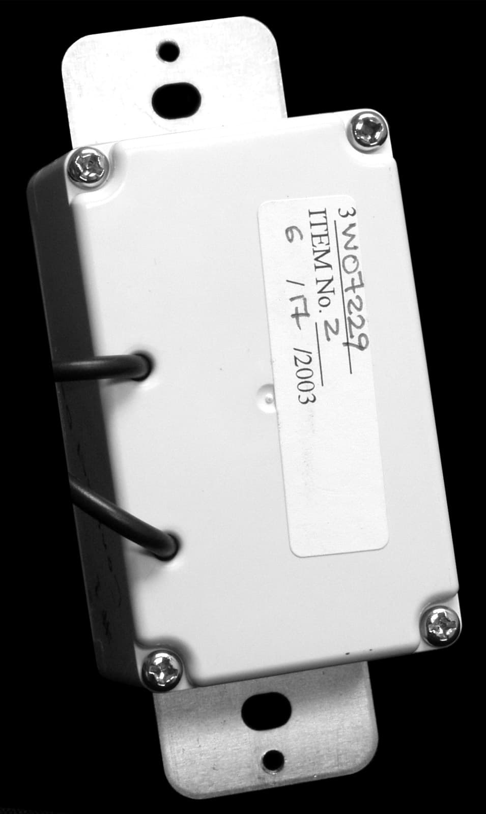
Click to zoom
Application Details
- Equipment Class
- DSC - Part 15 Security/Remote Control Transmitter
- Date of Grant
- Jul 01, 2003
- Application Purpose
- Original Equipment
- Date of Application
- Jul 01, 2003
- Equipment Note
- 6023TX Wall Switch Transmitter
- Frequency Range
- 315.00000000 - 315.00000000
- Company
- HeathCo LLC
- Country
- United States
Documents & Files
Document Text
Text extracted from the exhibit documents filed with the FCC. Open a document above to read the original.
Users Manual
DRAFT COPY 3-WAY WALL SWITCH TRANSMITTER DIM DIM Important: This product should be used in conjunction with the Wall Switch Receiver. 3-way circuit wiring is required to install and use this product. Note: If you are not familiar with electrical wiring, consult an electrician about installation. In addition, some local building codes may require installation by a qualified electrician. Installation 1. Select light switch to be replaced by 3-way wall switch transmitter. 2.Turn off the power to the light switch circuit before you proceed. Do this at your circuit breaker or fuse box. 3. Remove the existing wall plate and switch. Label the wires on the existing switch according to the diagram in Figure 1. Note: Typical 3-way wiring is shown. Actual wiring may vary. WHITE FROM POWER SOURCE WHITE (Neutral)WHITE 1 BLACK (Hot) GREEN (Ground) 2 RED 4 BLACK 3 BLACK Figure 1 (Typical 3-Way Wiring Shown) 4. Disconnect the two power wires and the ground wire. 5. Connect the wires of the 3-way wall switch transmit- ter and wall switch receiver to the wires in the junction box as shown in Figure 2. Use the supplied wire connectors to secure the wires (see Figure 2). Note: Either black wire on the transmitter and receiver can be used to connect to the hot wire. 6. Connect the green ground wire from transmitter to the ground wire removed from old switch. Use one of the supplied wire connectors to secure the wires (see Figure 3). 7. Check wire connections to make sure they are se- cure and that no bare wires are exposed. 8. Position the wall switch transmitter in the junction box with the DIM button located to the right. Use the two wall switch screws (long) supplied to mount the receiver to the junction box (see Figure 3). Push excess wiring into junction box while you do this, bending the wires to fit if necessary. GREEN (Ground) WHITE FROM POWER SOURCE 1 BLACK (Hot) WHITE (Neutral) SL-6017 WHITE SL-6023 DIM 2 RED 3 BLACK 4 BLACK Figure 2 Figure 3 Wall Switch Screw Junction Box Wall Switch ON/OFF Button DIM Button Wall Power Disconnect Switch Cover Plate Cover Plate Screw 9. Mount the wall plate to the wall switch transmitter with the screws (short) provided. 10. Turn on the power to the light switch circuit. Do this at your circuit breaker or fuse box. DRAFT COPY Operation 1. Verify the power disconnect switch on the transmitter and receiver is in the ON (right side) position. 2. Push the ON (top) button and release. The light should turn on full bright. Note: If you are controlling a lamp, make sure it is connected to the switched outlet and the lamp is switched on. 3. Push the OFF (bottom) button and release. The light should turn off. 4.Push the DIM button and release. The light should turn on at 50% brightness (or last setting). Note: Receiver remembers the last DIM setting used. To recall last DIM setting, push and release the DIM button. 5. Continue to press the DIM button until the desired dim level is reached. Note: There are 5 DIM settings ranging from 15% to 90% brightness. Note: The DIM setting defaults to 50% in the event of a power failure. Important: Wait 1 to 2 seconds after you press a trans- mitter button before you press it again to allow the transmission to be completed. Note: If light does not turn on or intermittently turns on and off when transmitter buttons are pushed, see Trouble- shooting Guide. Bulb Replacement Move the power disconnect switch on the transmitter and receiver to the OFF (left side) position. Replace bulb(s). Note: The power disconnect switch on the transmitter prevents the unit from sending any signals to the re- ceiver. The power disconnect switch on the receiver prevents it from applying power to the load that it controls. REGULATORY INFORMATION This device complies with Part 15 of the FCC Rules and RSS-210 of Industry Canada. Operation is subject to the following two conditions: (1) this device may not cause harmful interference, and (2) this device must accept any interference received, including interference that may cause undesired operation. The term "IC:" before the radio certification number only signifies that Industry Canada technical specifications were met. The user is cautioned that changes or modifications not expressly approved by the party responsible for regula- tory compliance could void the user’s authority to operate the equipment.
Block Diagram
DESA Specialty Products Confidential 6/12/2003 DESA Specialty Products Wireless Wall Switch Transmitter Model #: 6023-TXDescription: 315 MHz Wireless Wall Switch TransmitterFCC ID (proposed): BJ4-60WRC23TX Transmitter Circuit Block Diagram Power Supply N/O Momentary Tact Switch 12-Bit (5-Volt DC from & 8 to 3-line Binary Priority Enconder IC RF Oscillator 120 VAC Source) Enconder IC (3 KHz Data Rate) (315 MHz) & 4-Position Dipswitch File: 6023-TX Block Diagram
ID Label/Location Info
DRAFT COPY DESA Specialty Products™ Bowling Green, KY Model 6023-TX WIRELESS WALL SWITCH INPUT: 120 VAC 60 Hz Made in China390-6023XX-TX1A For Indoor Use Only This device complies with part 15 of the FCC Rules. Operation is sub- ject to the following two conditions: (1) this device may not cause harm- ful interference, and (2) this device must accept any interference re- ceived, including interference that may cause undesired operation. U.S. Patent 5,818,128 ® CUS LISTED FCC ID: BJ4-60WRC23TX IC: 3984A-6023TX
Operational Description
DESA International 6/4/2003 Confidential 6023-TX AC Wireless Wall Transmitter AC Wireless Wall Transmitter Model Number: 6023-TX General Description: The 6023-TX AC Wireless Wall Transmitter is a transmitting device used for remotely controlling room lights by utilizing RF transmission technology and a compatible RF receiving device. The device is capable of transmitting three separate commands, which are used by the compatible receiver to turn the room lights ON or OFF or to dim the lights. The housing, front cover, and pushbuttons are made of an ABS plastic (PA765A) and the mounting plate is made of 16 gauge sheet metal. The assembly is designed to mount to a standard single-gang junction box. The electrical circuitry is comprised of a 5-Volt DC power supply, 3 tact switches, one 4- position dipswitch, a CMOS 12-bit encoder IC, a 315 MHz RF oscillator circuit, and complementary passive components. The power supply is a half-wave rectifier with voltage-dropping resistor/capacitor and 5-volt regulator. The power supply circuitry is located on the rear circuit board and the RF and encoder circuitry is located on the front circuit board. The two boards are connected together with a ribbon cable. The printed circuit boards are double-sided and have a 94V-0 rating. Specifications: • Input: 120 VAC, 60 Hz • Circuit voltage: ~5.0 volts DC. • RF Carrier Frequency: 315 MHz • Modulated Data Frequency: 3.0 KHz • User-selectable address codes: 16 Theory of Operation: The wireless transmitter is normally off with the RF transmission starting when one of the pushbuttons is depressed momentarily. When one of the three normally open pushbuttons is depressed, the 5-volt power supply output is connected to the encoder IC and RF circuitry. When the circuit is completed, the encoder outputs a 3 KHz 12-bit transmission to the RF oscillator circuit transmitting the information at a carrier frequency of 315 MHz. The encoder continues to transmit as long as the pushbutton is depressed. The 12-bit output consists of an 8-bit address and 4 bits of data. The user-selectable address is set with a four-position dipswitch. The other 4 address lines are permanently set. The receiving unit to be controlled is set to the same address as the wireless transmitter. DESA International 6/4/2003 Confidential 6023-TX AC Wireless Wall Transmitter Theory of Operation (continued) The wireless switch is capable of sending 3 different commands to a compatible receiver. It can transmit an ON, OFF, and DIM code. When the ON, OFF, or DIM switch is depressed, the corresponding data bit is pulled low (connected to ground via the tact switch). When the receiving unit receives and decodes the signal, it executes the desired ON, OFF, or DIM operation. Product Pictorials: Front View with Dipswitch DESA International 6/4/2003 Confidential 6023-TX AC Wireless Wall Transmitter Rear View with Earth Ground Attachment DESA International 6/4/2003 Confidential 6023-TX AC Wireless Wall Transmitter Exploded Isometric View DESA International 6/4/2003 Confidential 6023-TX AC Wireless Wall Transmitter Wiring Diagram: DESA International 6/4/2003 Confidential 6023-TX AC Wireless Wall Transmitter Electrical Schematic:
Parts List/Tune Up Info
DESA Specialty Products6/4/2003 6023-TX Bill of Materials RefDes ValueDescriptionVoltageWattage C1100pFSMD Capacitor C29.1pFSMD Capacitor C3Not InstalledSMD Capacitor C4100nFSMD Capacitor C52.2pFSMD Capacitor C6100pFSMD Capacitor C71nFSMD Capacitor C8100nFSMD Capacitor C9100pFSMD Capacitor C10.1uFHigh Voltage Capacitor250V C11.68uFHigh Voltage Capacitor250V C12100nFCeramic Disc Capacitor C131000uFRadial Polarized Capacitor16V C14470uFRadial Polarized Capacitor6.3V C15100nFCeramic Disc Capacitor D11N474212 Volt Zener Diode D21N4003Diode JP14-Position SwitchDip Switch Q1MMBTH10LNPN Bipolar Transistor R1470Resisto r R251KResistor R31MegResistor R451KResistor R522Resistor R60 OhmResistor R70 OhmResistor R8100KResistor R9100KResistor R10100KResistor R11100KResistor R12100KResistor R13100KResistor R1456Flame Proof Resistor1 Watt R15470KResistor1/4 WATT R160 OhmResistor R170 OhmResistor R180 OhmResistor R190 OhmResistor S1ONPush Button, Normally Open S2OFFPush Button, Normally Open S3STEP DIM,DIM+Push Button, Normally Open S5POWERSwitch, Single Pole, Double Throw U1HT-12EEncoder U274HC1488-Line to 3-Line ENCODER U3LM78L055 Volt Regulator X1315Mh zSAW Resonator
Schematics
Copyright 2003DESA Specialty Products
Test Report
Master:PT15-Sub-C-15231 Date: November 12, 2001 Test Report: 3W07229 Applicant: Desa International PO Box 90004 2901 Industrial Ave Bowling Green KY 42102 Equipment Under Test: 6023TX Wireless Transmitter (EUT) FCC ID: BJ4-60WRC23TX In Accordance With: FCC Part 15, Subpart C, 15.231 Tested By: Nemko Canada Inc. 303 River Road, R.R. 5 Ottawa, Ontario K1V 1H2 Authorized By: Kevin Carr, EMC Specialist Date: 27 June 2003 Total Number of Pages: 22 Nemko Canada Inc. FCC PART 15, SUBPART C, 15.231 PROJECT NO.: 3W07229 EQUIPMENT: 6023TX Page 2 of 18 Table of Contents Section 1. Summary of Test Results ...................................................................................... 3 Section 2. Equipment Under Test .......................................................................................... 5 Section 3. Transmission Requirements ................................................................................. 9 Section 4. Radiated Emissions .............................................................................................. 11 Section 5. Occupied Bandwidth ........................................................................................... 14 Section 6. Block Diagrams .................................................................................................... 21 Section 7. Test Equipment List ............................................................................................. 22 Nemko Canada Inc. FCC PART 15, SUBPART C, 15.231 PROJECT NO.: 3W07229 EQUIPMENT: 6023TX Page 3 of 18 Section 1. Summary of Test Results General All measurements are traceable to national standards. These tests were conducted on a sample of the equipment for the purpose of demonstrating compliance with Part 15, Subpart C. All tests were conducted using measurement procedure ANSI C63.4-1992. Radiated emissions are made on an open area test site. A description of the test facility is on file with the FCC. THIS TEST REPORT RELATES ONLY TO THE ITEM(S) TESTED. THE FOLLOWING DEVIATIONS FROM, ADDITIONS TO, OR EXCLUSIONS FROM THE TEST SPECIFICATIONS HAVE BEEN MADE. See “ Summary of Test Data”. TESTED BY: _______________________________ DATE: 27 June 2003 Glen Westwell, Wireless Technologist Nemko Canada Inc. authorizes the above named company to reproduce this report provided it is reproduced in its entirety and for use by the company’s employees only. Any use which a third party makes of this report, or any reliance on or decisions to be made based on it, are the responsibility of such third parties. Nemko Canada Inc. accepts no responsibility for damages, if any, suffered by any third party as a result of decisions made or actions based on this report. This report applies only to the items tested. Nemko Canada Inc. FCC PART 15, SUBPART C, 15.231 PROJECT NO.: 3W07229 EQUIPMENT: 6023TX Page 4 of 18 Summary Of Test Data Name of Test Para. Number Results Transmission Requirements 15.231(a) Complies Radiated Emissions 15.231(b) Complies Occupied Bandwidth 15.231(c) Complies Frequency Tolerance 15.231(d) NA Periodic Alternate Field Strength Requirements 15.231(e) NA Powerline Conducted Emissions 15.207 Complies Note: Test Conditions: Indoor Temperature: 23°C Humidity: 51% Outdoor Temperature: 30°C Humidity: 51% Nemko Canada Inc. FCC PART 15, SUBPART C, 15.231 PROJECT NO.: 3W07229 EQUIPMENT: 6023TX Page 5 of 22 Section 2. Equipment Under Test General Equipment Information Manufacturer: Desa International Equipment 315 MHz Wireless Transmitter Model No.: 6023TX Serial No.: None Date Received In Laboratory: 17 June 2003 Nemko Identification No.: #1 Transmit Frequency: 315MHz Fixed Modulation: Pulse Carrier On Off (PCM) Emission Designator: 28K8L1D Nemko Canada Inc. FCC PART 15, SUBPART C, 15.231 PROJECT NO.: 3W07229 EQUIPMENT: 6023TX Page 6 of 22 Nemko Canada Inc. FCC PART 15, SUBPART C, 15.231 PROJECT NO.: 3W07229 EQUIPMENT: 6023TX Page 7 of 22 Nemko Canada Inc. FCC PART 15, SUBPART C, 15.231 PROJECT NO.: 3W07229 EQUIPMENT: 6023TX Page 8 of 22 Nemko Canada Inc. FCC PART 15, SUBPART C, 15.231 PROJECT NO.: 3W07229 EQUIPMENT: 6023TX Page 9 of 22 Section 3. Transmission Requirements Para. No.: 15.231(a) Test Performed By: Glen Westwell Date of Test: 20 June 2003 Minimum Standard: 15.231(a) Continuous transmissions such as voice, video or data transmissions are not permitted. 15.231(a)(1) A manually operated transmitter shall employ a switch that will automatically deactivate the transmitter within not more than 5 seconds after being released. 15.231(a)(2) A transmitter activated automatically shall cease transmission within 5 seconds of activation. 15.231(a)(3) Periodic transmissions at regular pre-determined intervals are not permitted. However polling or supervisory transmissions to determine system integrity of transmitters used in security or safety applications are allowed if the periodic rate of transmission does not exceed one transmission of not more than one second duration per hour for each transmitter. 15.231(a)(4) Intentional radiators which are employed for radio control purposes during emergencies involving fire, security, and safety of life, when activated to signal an alarm, may operate during the pendency of the alarm. Test Results: Complies Test Data: Compliance was determined by verification of technical specifications and a functional test on the equipment. Nemko Canada Inc. FCC PART 15, SUBPART C, 15.231 PROJECT NO.: 3W07229 EQUIPMENT: 6023TX Page 10 of 22 Rationale for Compliance with Transmission Requirements 15.231(a)(1) : The transmitter is deactivated immediately upon releasing the push button switch (see plot below). 15.231(a)(2) : No automatic activation. 15.231(a)(3) : No periodic, polling, or supervision transmissions. 15.231(a)(4) : NA Nemko Canada Inc. FCC PART 15, SUBPART C, 15.231 PROJECT NO.: 3W07229 EQUIPMENT: 6023TX Page 11 of 22 Section 4. Radiated Emissions Para. No.: 15.231(b) Test Performed By: Glen Westwell Date of Test: 20 June 2003 Minimum Stan…
Text truncated - open the document above for the full version.
Test Setup Photos
OATS Set Up CONDUCTED SET UP PHOTO
Contact Information
Applicant
Jeff Bessinger(Associate Regulatory Engineer)
Test Firm
Nemko Canada Inc.Stuart Beck
Technical Specifications
| # | Rule Parts | Frequency Range | Power Output |
|---|---|---|---|
| 1 | 15.231 | 315 MHz - 315 MHz | - |
Other Applications from HeathCo LLC

BJ4-9309
Apr 01, 2020Connected LED video security motion light
Equipment Class
DTS - Digital Transmission System
BJ4-9000
Mar 25, 2020Connected Wired Decorative Motion Light
Equipment Class
DTS - Digital Transmission System
BJ4-WLTRX9600
Jan 05, 2020Video Doorbell with 2.4GHz wifi
Equipment Class
DTS - Digital Transmission System
BJ4-WLTX204
Jul 19, 2015Wireless Doorbell extender Kit
Equipment Class
DSC - Part 15 Security/Remote Control Transmitter
BJ4-WLTX208
Jul 06, 2015Wireless Door Chime Transmitter
Equipment Class
DSC - Part 15 Security/Remote Control Transmitter