BJ4-61RWRC32TX6131 and 6132 Transmitters
HeathCo LLC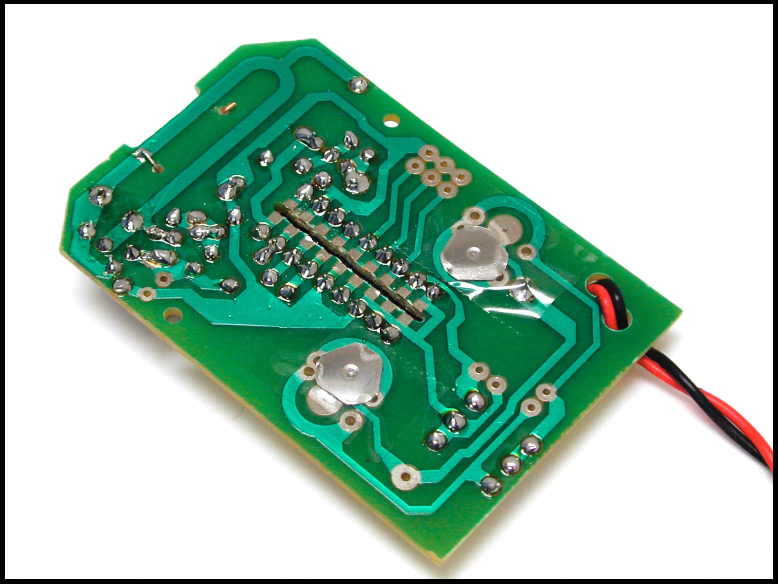
Click to zoom
Application Details
- Equipment Class
- DSC - Part 15 Security/Remote Control Transmitter
- Date of Grant
- Oct 01, 2001
- Application Purpose
- Original Equipment
- Date of Application
- Aug 12, 2001
- Equipment Note
- 6131 and 6132 Transmitters
- Frequency Range
- 315.00000000 - 315.00000000
- Company
- HeathCo LLC
- Country
- United States
Documents & Files
Document Text
Text extracted from the exhibit documents filed with the FCC. Open a document above to read the original.
Users Manual
BATTERY © 2001 DESA International598-1004-03 Features •Add switched outlets with the convenience of operation from a single hand-held transmitter. • Includes one indoor/outdoor module & one indoor module. Wireless Indoor and Outdoor Remote Control Models SL/TT-6132 Transmitter Operational Instructions Note: You will need to buy a 9-volt alkaline battery for the remote control. In typical use, this battery will last about one year. Remove the battery during extended periods of non-use. 1. Install the 9-volt battery. Remove the cover from the back of the transmitter by pressing on it with your thumb and sliding it off as shown. Plug in the battery and slide the cover back onto the transmitter. Cover Transmitter SL-6139 Indoor/Outdoor Module SL-6136 Indoor Module Page 2 598-1004-03 Indoor/Outdoor Module Operation 1. Plug in Indoor/Outdoor Module. Remember, the Indoor/ Outdoor Module requires a grounded outlet. If you do not have a grounded outlet, you may want to contact an electrician to upgrade your electrical system. If you are using the Indoor/ Outdoor Module outdoors, see extra precautions below. Precautions When Using the Indoor/Outdoor Module •The Module must be oriented with the power outlet down to prevent rain from entering the unit. See the illustration below. •Hang the module on a nail or screw as shown. There is a hole in the back for this purpose. DO NOT allow it to hang by the cord. •Note in the illustration that the module is lo- cated below the wall outlet. This is to prevent rain from running down the cord into the wall outlet. •Note: The National Electrical Code and Cana- dian Electrical Code (and most local codes) require that outside outlets be protected by a Ground Fault Interrupter (GFI). Hole to hang unit Power Outlet 2. Plug in the devices you wish to control. Caution: Do not exceed the maximum load specifications (see page 3). 3. To check operation, press button on the left side of transmitter (see icon). The light/appliance should turn on immediately. Important: Wait at least 3 seconds after you press the button before pressing it again to allow the transmission to be com- pleted. Page 3 598-1004-03 Indoor Module Operation 1. Install the Indoor Module as shown. Indoor Module 2. Plug in the device(s) you wish to control. Caution: do not exceed the specifications listed on the next page. Turn the device on. 3. To check the operation, press the right side button on the transmitter. The light/appliance should turn on immediately. Important: Wait at least 3 seconds after you press the transmit- ter button before you press it again to allow the transmission to be completed. Note:The SL-6132 system works with other Heath ® /Zenith wireless switch products with the same channel designation ('F', 'G', 'H'). SPECIFICATIONS Range . . . . . . . . . . . . . . . Up to 50 feet (15.2 M) Rated Voltage . . . . . . . . . 120 VAC, 60 Hz Battery . . . . . . . . . . . . . . . 9-volt alkaline SL-6139SL-6136 Max. Load, resistive ................ 13 A................................. 5 A tungsten ................................. 960 W ............................ 500 W fluorescent .............................. 960 W ............................ 300 W motor ..................................... 1/3 H.P. .......................... 1/3 H.P. Page 4 598-1004-03 TROUBLESHOOTING GUIDE Regulatory Information This device complies with Part 15 of the FCC Rules and RSS-210 of Industry Canada. Operation is subject to the following two conditions: (1) this device may not cause harmful interference, and (2) this device must accept any interference received, including interference that may cause undesired operation. The user is cautioned that changes or modifications not expressly approved by the party responsible for regulatory compliance could void the user’s authority to operate the equipment. Do not send products, please call the number listed below: Technical Service: USA call 1-800-858-8501/Canada call 905- 826-8010 DESA International, Inc. P.O. Box 90004, Bowling Green, KY 42102-9004 SYMPTOM Light does not come on. POSSIBLE CAUSE 1. Circuit breaker or fuse is turned off. 2. Switch on lamp is turned off. 3. Bulb is defective. 4. Signals from transmitter are being blocked, or transmitter is out of range. Check for metal objects that could block the signal, or reposition the transmitter. 5. Weak battery in the transmitter. 1. Switching too fast. Wait 3 seconds between pushing the transmitter button. 2. Same as 4 & 5 above. 1. Short term power line failure. 2. Another transmitter on the same channel. Light does not turn off. Light comes on randomly. If you experience a problem, follow this guide. You may also want to visit our Web site at: www.desatech.com. If the problem persists, call for assistance at 1-800-858-8501 7:30 AM to 4:30 PM Central Time weekdays. Page 5 598-1004-03 YOUR HEATH ® /ZENITH FIVE YEAR LIMITED WARRANTY This is a "Limited Warranty" which gives you specific legal rights. You may also have other rights which vary from state to state or province to province. For a period of five years from the date of purchase, any malfunction caused by factory defective parts or workmanship will be corrected at no charge to you. Batteries are not covered. To obtain a refund or a replacement, return the product to the place of purchase. Not Covered - Repair service, adjustment and calibration due to misuse, abuse or negligence, light bulbs and other expendable items are not covered by this warranty. Unauthorized service or modification of the product or of any furnished component will void this warranty in its entirety. This warranty does not include reimbursement for incon- venience, installation, setup time, loss of use, or unauthorized service. This warranty covers only Heath ® /Zenith assembled products and is not extended to other equipment and components that a customer uses in conjunction with our products. THIS WARRANTY IS EXPRESSLY IN LIEU OF ALL OTHER WAR- RANTIES, EXPRESS OR IMPLIED, …
Text truncated - open the document above for the full version.
Block Diagram
REF. No: (2 button)REF. No: (1 button) SL-6132-TXSL-6131-TX BJ4-61RWRC32TXBJ4-61RWRC32TX Product: SL-6132Products: SL-6135, SL-6139 Transmitter Circuit Block Diagram Power Supply (9VDC Battery) ENCODER IC (3kHz) Oscillator (315MHz) Antenna (Helical, Internal) 7/17/2001Block Diagrams of 6132 TX.xls
Operational Description
6132 Remote Control Input: 9V DC battery Output: Switched power by Push button Voltage: ~5.6V DC supply, regulated by zener diode and transistor power supply arrangement. Frequency: 315 MHz The power supply is disconnected from the battery unless one of the push buttons is pushed. Depending on which button is pushed, a different digital code is transmitted. This allows the transmitter to send data addressing two different devices. The address of the remote control can be changed at production time. It is capable of up to 8 addresses. Address changes affect the coded address information only. The customer cannot change the addressing of this unit. As a secondary arrangement, the remote can be built as a one button remote. This requires removal of D2 and D3. Also some jumper changes are required. The jumper change makes both sides work as one common push button for the single button version.
Parts List/Tune Up Info
PCB assembly forTransmitter module(6132)(181-6132-TX01) 006-0105-12RES. C.F. 1M OHM 0.25W1R2 006-0222-12RES. C.F. 2.2K OHM 0.25W1R1 006-0220-12RES. C.F. 22 OHM 0.25W 5%1R5 006-0273-12RES. C.F. 27K OHM 0.25W 5%1R4 006-0563-12RES. C.F.120K OHM 0.25W 5%1R3 CER CAP 3.3PF +-0.25PF 50V NPO1C4 021-P045CER CAP 4.7PF 50V +-0.25PF NPO1C6 CER CAP 2.2PF 50V +-.25PF NPO1C3 021-P074CER. CAP. 20pf 50V 5% NPO1C5 021-P080CER. CAP. 47pf 50V 5% NPO1C7 027-P056MYLAR CAP 0.01UF1C8 031-P001-01TRIMMER CAP. 2.0-5pf DIA:5mm seal type1C2 045-P006-01CHOKE COIL 1.5uH AXIAL 6.0mm1L1 HELICAL ANTENNA1L2 056-0084DIODE 1N4148 200mA 75V 1/2W3D1, D2, D3 056-P022ZENER 6.2V 0.5W1Z1 417-P015TRANSISTOR NPN 2SC1923-Y1Q2 417-0875TRANSISTOR NPN 2N39041Q1 389-P036-01XXIC HT-12E COB ASSEMBLY1U1 432-P016DIMPLE 8MM WITH 2MM FEET2 085-P127PCB FOR SL-6135/9-new Tx NICKLE PLATED1 Casing assembly 810-P234SCREW M2X10PT1 810-P235SCREW M2X8PT2 092-0921-AB12FRONT CABINET,ABS BLACK SL/TT-1 092-0922-AB11REAR CABINET, ABS BLACK1 092-0923-AB11BATTERY DOOR, ABS BLACK1 092-0925-AG11PRESS BUTTON, SINGLE GREY2 344-0124-6000WIRE #24 6MM1 432-0798-01BATTERY CLIP 9V1 * PARTS IN YELLOW ARE ADDED/REMOVED, DEPENDING ON ONE OR TWO BUTTON VERSION * PARTS IN YELLOW ARE ADDED/REMOVED, DEPENDING ON ONE OR TWO BUTTON VERSION
Test Report
Master:PT15-Sub-C-15231 Date: August 2, 2001 Test Report:1W04149 Applicant:Desa International PO Box 9004, 2701 Industrial Avenue Bowling Green, KY 42101-9004 USA Equipment Under Test:6131/6132 One/Two Button Transmitter (EUT) In Accordance With:FCC Part 15, Subpart C, 15.231 Tested By:Nemko Canada Inc. 3325 River Road, R.R. 5 Ottawa, Ontario K1V 1H2 Authorized By: R. Grant, Wireless Group Manager Date: Total Number of Pages:20 Nemko Canada Inc. FCC PART 15, SUBPART C, 15.231 PROJECT NO.: 1W04149 EQUIPMENT: 6131/6132 One/Two Button Transmitter Page 2 of 20 Table of Contents Section 1. Summary of Test Results.......................................................................................... 3 Section 2. Equipment Under Test ............................................................................................. 5 Section 3. Transmission Requirements .................................................................................. 10 Section 4. Radiated Emissions................................................................................................. 14 Section 5. Occupied Bandwidth.............................................................................................. 16 Section 6. Block Diagrams.......................................................................................................19 Section 7. Test Equipment List ............................................................................................... 20 Nemko Canada Inc. FCC PART 15, SUBPART C, 15.231 PROJECT NO.: 1W04149 EQUIPMENT: 6131/6132 One/Two Button Transmitter Page 3 of 20 Section 1.Summary of Test Results General All measurements are traceable to national standards. These tests were conducted on a sample of the equipment for the purpose of demonstrating compliance with Part 15, Subpart C. All tests were conducted using measurement procedure ANSI C63.4-1992. Radiated emissions are made on an open area test site. A description of the test facility is on file with the FCC. THIS TEST REPORT RELATES ONLY TO THE ITEM(S) TESTED. THE FOLLOWING DEVIATIONS FROM, ADDITIONS TO, OR EXCLUSIONS FROM THE TEST SPECIFICATIONS HAVE BEEN MADE. See “ Summary of Test Data”. NVLAP LAB CODE: 100351-0 TESTED BY: _____________________________________ DATE: ___________________ Wayne Clarke, Wireless Technologist Nemko Canada Inc. authorizes the above named company to reproduce this report provided it is reproduced in its entirety and for use by the company’s employees only. Any use which a third party makes of this report, or any reliance on or decisions to be made based on it, are the responsibility of such third parties. Nemko Canada Inc. accepts no responsibility for damages, if any, suffered by any third party as a result of decisions made or actions based on this report. This report applies only to the items tested. Nemko Canada Inc. FCC PART 15, SUBPART C, 15.231 PROJECT NO.: 1W04149 EQUIPMENT: 6131/6132 One/Two Button Transmitter Page 4 of 20 Summary Of Test Data Name of TestPara. NumberResults Transmission Requirements15.231(a)Complies Radiated Emissions15.231(b)Complies Occupied Bandwidth15.231(c)Complies Frequency Tolerance15.231(d)N/A Periodic Alternate Field Strength Requirements15.231(e)N/A Powerline Conducted Emissions15.207N/A Test Conditions: IndoorTemperature: 24 °C Humidity:33 % OutdoorTemperature: 28 °C Humidity:79% Nemko Canada Inc. FCC PART 15, SUBPART C, 15.231 PROJECT NO.: 1W04149 EQUIPMENT: 6131/6132 One/Two Button Transmitter Page 5 of 20 Section 2.Equipment Under Test General Equipment Information Manufacturer:Desa International Model No.:6131: One Button Transmitter 6132: Two Button Transmitter Serial No.:None Date Received In Laboratory:August 3, 2001 Nemko Identification No.:Item #’s 11 & 12 Both EUTs were tested and results of both tests are included: Model: 6131 Duty Cycle=20 Log On Time ms 100 ms =20 Log 5 x 10.17ms 100ms =20 Log 50.85 100ms =20 Log 0.5085 =-5.9 dB Model: 6132 Duty Cycle=20 Log On Time ms 100 ms =20 Log 5 x 11.17ms 100ms =20 Log 55.85 100ms =20 Log 0.55085 =-5.1 dB Nemko Canada Inc. FCC PART 15, SUBPART C, 15.231 PROJECT NO.: 1W04149 EQUIPMENT: 6131/6132 One/Two Button Transmitter Page 6 of 20 Nemko Canada Inc. FCC PART 15, SUBPART C, 15.231 PROJECT NO.: 1W04149 EQUIPMENT: 6131/6132 One/Two Button Transmitter Page 7 of 20 Nemko Canada Inc. FCC PART 15, SUBPART C, 15.231 PROJECT NO.: 1W04149 EQUIPMENT: 6131/6132 One/Two Button Transmitter Page 8 of 20 Nemko Canada Inc. FCC PART 15, SUBPART C, 15.231 PROJECT NO.: 1W04149 EQUIPMENT: 6131/6132 One/Two Button Transmitter Page 9 of 20 Nemko Canada Inc. FCC PART 15, SUBPART C, 15.231 PROJECT NO.: 1W04149 EQUIPMENT: 6131/6132 One/Two Button Transmitter Page 10 of 20 Section 3.Transmission Requirements Para. No.: 15.231(a) Test Performed By: Wayne ClarkeDate of Test: July 31, 2001 Minimum Standard:15.231(a) Continuous transmissions such as voice, video or data transmissions are not permitted. 15.231(a)(1) A manually operated transmitter shall employ a switch that will automatically deactivate the transmitter within not more than 5 seconds after being released. 15.231(a)(2) A transmitter activated automatically shall cease transmission within 5 seconds of activation. 15.231(a)(3) Periodic transmissions at regular pre-determined intervals are not permitted. However polling or supervisory transmissions to determine system integrity of transmitters used in security or safety applications are allowed if the periodic rate of transmission does not exceed one transmission of not more than one second duration per hour for each transmitter. 15.231(a)(4) Intentional radiators which are employed for radio control purposes during emergencies involving fire, security, and safety of life, when activated to signal an alarm, may operate during the pendency of the alarm. Test Results:Complies. Test Data:Compliance was determined by verification of technical specifications and a functional test on the equipment. Nemko Canada Inc. FCC …
Text truncated - open the document above for the full version.
Contact Information
Applicant
Jeff Bessinger(Associate Regulatory Engineer)
Technical Contact
Nemko Canada Inc.Ruby Dulmage
[email protected]800-563-6336
3325 River Road · Ottawa, Ontario · Canada
Non-Technical Contact
Nemko Canada Inc.Ruby Dulmage
[email protected]800-563-6336
Test Firm
Nemko Canada Inc.Stuart Beck
Technical Specifications
| # | Rule Parts | Frequency Range | Power Output |
|---|---|---|---|
| 1 | 15C | 315 MHz - 315 MHz | - |
Other Applications from HeathCo LLC

BJ4-9309
Apr 01, 2020Connected LED video security motion light
Equipment Class
DTS - Digital Transmission System
BJ4-9000
Mar 25, 2020Connected Wired Decorative Motion Light
Equipment Class
DTS - Digital Transmission System
BJ4-WLTRX9600
Jan 05, 2020Video Doorbell with 2.4GHz wifi
Equipment Class
DTS - Digital Transmission System
BJ4-WLTX204
Jul 19, 2015Wireless Doorbell extender Kit
Equipment Class
DSC - Part 15 Security/Remote Control Transmitter
BJ4-WLTX208
Jul 06, 2015Wireless Door Chime Transmitter
Equipment Class
DSC - Part 15 Security/Remote Control Transmitter