BJ4-61RWRC33TXRemote Wireless Switch Transmitter
HeathCo LLC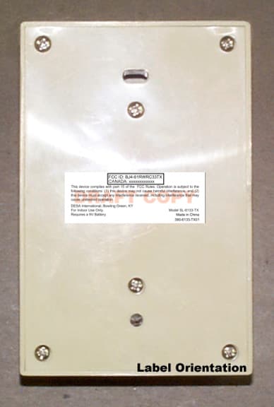
Click to zoom
Application Details
- Equipment Class
- DXX - Part 15 Low Power Communication Device Transmitter
- Date of Grant
- Nov 26, 2001
- Application Purpose
- Original Equipment
- Date of Application
- Nov 26, 2001
- Equipment Note
- Remote Wireless Switch Transmitter
- Frequency Range
- 315.00000000 - 315.00000000
- Company
- HeathCo LLC
- Country
- United States
Documents & Files
Document Text
Text extracted from the exhibit documents filed with the FCC. Open a document above to read the original.
Users Manual
Wireless Lamp/ Outlet Modules Models SL-6136 & SL-6138 Your wireless switched module system includes: •Remote wall switch •Receiver lamp module (SL-6138) or outlet module (SL-6136) •Two #8 x 2" wood screws •This manual You'll need to buy a 9-volt alkaline battery for the wireless switch. In typical use, this battery will last one year. Multiple channels (A thru E) are available so that you can operate several systems at different locations in your home. If you purchase more than one system, make sure you select different operating channels, or they will interact with each other. If you purchase a different switch plate to match your decor, make sure it is not a metal plate. Metal wall plates will reduce the operating range. © 2000 Heath Co. a div. of DESA International595-5627-01 Installation 1. Install the 9-volt battery. Remove the switch cover from the transmitter as shown (save the two screws). Snap the battery clips over the battery terminals and set the battery into its compartment. Battery Compartment Remote Switch -2- 2. Turn off the power to the outlet or lamp to be con- trolled. Install the switched outlet or lamp module as shown. 3. For the SL-6136, plug in the device(s) you wish to control. Screw the light bulb into the SL-6138. Caution: do not exceed the specifica- tions listed on the next page. Turn the power back on. 4. To check the operation, hold the remote switch at the desired location and switch it on. The appliance should turn on immediately. Important: Wait at least 3 seconds after you switch the remote switch on or off before you switch it again to allow the transmission to be completed. Turn the appliance off and back on several times. If the switch appears unreliable, move the remote switch until the appliance switches reliably. 5. Mount the remote switch at the desired location with the two wood screws pro- vided. Note: Your particular installation may require different mounting hardware. 6. Install the switch plate on the remote switch with the screws provided. SL-6136 SL-6138 -3- TROUBLESHOOTING GUIDE SYMPTOM Appliance does not come on. POSSIBLE CAUSE 1. Circuit breaker or fuse is turned off. 2. Switch on appliance is turned off. 3. Lamp or appliance is defective. 4. Signals from remote switch are being blocked, or remote switch is out of range. Check for metal ob- jects that could block the signal, or reposition the remote switch. 5. Weak battery in the remote switch. 1. Switching too fast. Wait 3 seconds before switching the remote switch. 2. Same as 4 & 5 above. 1. Short term power line failure. 2. Another remote switch on the sam e channel. Appliance does not turn off. Appliance comes on randomly. If you experience a problem, follow this guide. SPECIFICATIONS Range .............................................................. Up to 100 feet (30.5 m) Rated Voltage ................................................. 120 VAC, 60 Hz Maximum Load SL-6136 ................................. 500 Watts incandescent 400 Watts TV 300 Watts fluorescent 1/3 H.P. motor Maximum Load SL-6138 ................................ 150 Watts incandescent Battery ............................................................. 9-volt alkaline Heath/Zenith reserves the right to discontinue products and to change specifications at any time without incurring any obligation to incorporate new features in products previously sold. Regulatory Information The user is cautioned that changes or modifications not expressly approved by the party responsible for regulatory compliance could void the user's authority to operate the equipment. This device (Model 6136) complies with RSS-210 of Industry Canada. Operation is subject to the following two conditions: (1) this device may not cause interference, and (2) this device must accept any interference, including interference that may cause undesired operation of the device. -4- YOUR HEATH/ZENITH FIVE YEAR LIMITED WARRANTY This is a "Limited Warranty" which gives you specific legal rights. You may also have other rights which vary from state to state or province to province. For a period of five years from the date of purchase, any malfunction caused by factory defective parts or workmanship will be corrected at no charge to you. Batteries are not covered. To obtain a refund or a replacement, return the product to the place of purchase. Not Covered - Repair service, adjustment and calibration due to misuse, abuse or negligence, light bulbs and other expendable items are not covered by this warranty. Unauthorized service or modification of the product or of any furnished component will void this warranty in its entirety. This warranty does not include reimbursement for inconvenience, installation, setup time, loss of use, or unauthorized service. This warranty covers only Heath/Zenith assembled products and is not extended to other equipment and components that a customer uses in conjunction with our products. THIS WARRANTY IS EXPRESSLY IN LIEU OF ALL OTHER WARRANTIES, EXPRESS OR IMPLIED, INCLUDING ANY WARRANTY, REPRESENTATION OR CONDITION OF MERCHANT ABILITY OR THAT THE PRODUCTS ARE FIT FOR ANY PARTICULAR PURPOSE OR USE, AND SPECIFICALLY IN LIEU OF ALL SPECIAL, INDIRECT, INCIDENTAL, OR CONSEQUENTIAL DAMAGES. REPAIR OR REPLACEMENT SHALL BE THE SOLE REMEDY OF THE CUSTOMER AND THERE SHALL BE NO LIABILITY ON THE PART OF DESA FOR ANY SPECIAL, INDIRECT, INCIDENTAL, OR CONSEQUENTIAL DAMAGES, INCLUDING BUT NOT LIMITED TO ANY LOSS OF BUSINESS OR PROFITS, WHETHER OR NOT FORESEEABLE. Some states or provinces do not allow the exclusion or limitation of incidental or consequential damages, so the above limitation or exclusion may not apply to you. Retain receipt for warranty claims. Modelos SL-6136 & SL-6138 En su sistema módulo conmutable inalámbrico se incluye: •Un interruptor remoto de pared •Un módulo de la lámpara receptora (SL-6138) o un módulo de salida (SL-6136) •Dos tornillos para madera #8 x 2" •Este manual Ud. necesitará comprar una batería alcalina d…
Text truncated - open the document above for the full version.
Block Diagram
REF. No: SL-6133-TX BJ4-61RWRC33TX Products: 6133 Transmitter Circuit Block Diagram Power Supply (9VDC Battery) ENCODER IC (3kHz) Oscillator (315MHz) Antenna (Helical, Internal) 9/11/20016133 Block Diagram.xls
ID Label/Location Info
DRAFT COPY CANADA: xxxxxxxxxxxx This device complies with part 15 of the FCC Rules. Operation is subject to the following conditions: (1) this device may not cause harmful interference, and (2) this device must accept any interference received, including interference that may cause undesired operation. DESA International, Bowling Green, KY For Indoor Use Only. Model SL-6133-TX Requires a 9V Battery.
ID Label/Location Info
DRAFT COPY CANADA: xxxxxxxxxxxx This device complies with part 15 of the FCC Rules. Operation is subject to the following conditions: (1) this device may not cause harmful interference, and (2) this device must accept any interference received, including interference that may cause undesired operation. DESA International, Bowling Green, KY For Indoor Use Only. Model SL-6133-TX Requires a 9V Battery.
Operational Description
The 6133 Transmitter, when activated by its momentary switch, transmits a modulated code. Setting the jumpers inside the transmitting device configures this code. When a receiving device, programmed via jumpers to the same code as the transmitter, receives this code it then toggles its output state on or off. Shortly after the momentary switch is depressed, a signal is sent to the encoder to activate it and read it’s code (address) set by jumpers, then sends the code to be modulated onto the carrier frequency of 315Mhz which is then transmitted via the coil.
Test Report
Master:PT15-Sub-C-15231 Date: November 12, 2001 Test Report:1W04425 Applicant:Desa International PO Box 9004, 2701 Industrial Ave. Bowling Green, KY 92101-9004 USA Equipment Under Test:SL-6133 TX (EUT)315 MHz Remote Wireless Switch Transmitter FCC ID:BJ4-61RWRC33TX In Accordance With:FCC Part 15, Subpart C, 15.231 Tested By:Nemko Canada Inc. 3325 River Road, R.R. 5 Ottawa, Ontario K1V 1H2 Authorized By: R. Grant, Wireless Group Manager Date:November 13, 2001 Total Number of Pages:19 Authorized Copy:Soft Copy Nemko Canada Inc.FCC PART 15, SUBPART C, 15.231 PROJECT NO.: 1W04425 EQUIPMENT: SL-6133 TX 315 MHz Remote Wireless Switch Transmitter FCC ID: BJ4-61RWRC33TX Page 2 of 19 Table of Contents Section 1. Summary of Test Results......................................................................................3 Section 2. Equipment Under Test.........................................................................................5 Section 3. Transmission Requirements.................................................................................7 Section 4. Radiated Emissions.............................................................................................10 Section 5. Occupied Bandwidth..........................................................................................16 Section 6. Block Diagrams...................................................................................................18 Section 7. Test Equipment List...........................................................................................19 Nemko Canada Inc.FCC PART 15, SUBPART C, 15.231 PROJECT NO.: 1W04425 EQUIPMENT: SL-6133 TX 315 MHz Remote Wireless Switch Transmitter FCC ID: BJ4-61RWRC33TX Page 3 of 19 Section 1.Summary of Test Results General All measurements are traceable to national standards. These tests were conducted on a sample of the equipment for the purpose of demonstrating compliance with Part 15, Subpart C. All tests were conducted using measurement procedure ANSI C63.4-1992. Radiated emissions are made on an open area test site. A description of the test facility is on file with the FCC. THIS TEST REPORT RELATES ONLY TO THE ITEM(S) TESTED. THE FOLLOWING DEVIATIONS FROM, ADDITIONS TO, OR EXCLUSIONS FROM THE TEST SPECIFICATIONS HAVE BEEN MADE. See “ Summary of Test Data”. TESTED BY: DATE: November 12, 2001 Glen Westwell, Wireless Technologist Nemko Canada Inc., a testing laboratory, is accredited by the Standards Council of Canada. The tests included in this report are within the scope of this accreditation. The results apply only to the samples tested. Nemko Canada Inc. authorizes the above named company to reproduce this report provided it is reproduced in its entirety and for use by the company’s employees only. Any use which a third party makes of this report, or any reliance on or decisions to be made based on it, are the responsibility of such third parties. Nemko Canada Inc. accepts no responsibility for damages, if any, suffered by any third party as a result of decisions made or actions based on this report. This report applies only to the items tested. Nemko Canada Inc.FCC PART 15, SUBPART C, 15.231 PROJECT NO.: 1W04425 EQUIPMENT: SL-6133 TX 315 MHz Remote Wireless Switch Transmitter FCC ID: BJ4-61RWRC33TX Page 4 of 19 Summary Of Test Data Name of TestPara. NumberResults Transmission Requirements15.231(a)Complies Radiated Emissions15.231(b)Complies Occupied Bandwidth15.231(c)Complies Frequency Tolerance15.231(d)Complies Periodic Alternate Field Strength Requirements15.231(e)N/A Powerline Conducted Emissions15.207N/A Note:This device is battery operated only. Test Conditions: IndoorTemperature:24 °C Humidity:38 % OutdoorTemperature:10 °C Humidity:42 % Nemko Canada Inc.FCC PART 15, SUBPART C, 15.231 PROJECT NO.: 1W04425 EQUIPMENT: SL-6133 TX 315 MHz Remote Wireless Switch Transmitter FCC ID: BJ4-61RWRC33TX Page 5 of 19 Section 2.Equipment Under Test General Equipment Information Manufacturer: Heath / Zenith For Desa International Model No.: SL-6133TX Serial No.: None Date Received In Laboratory: October 17, 2001 Nemko Identification No.: Item #2 Transmitter Frequency: 315 MHz Emission Designator: 66K7L1D Nemko Canada Inc.FCC PART 15, SUBPART C, 15.231 PROJECT NO.: 1W04425 EQUIPMENT: SL-6133 TX 315 MHz Remote Wireless Switch Transmitter FCC ID: BJ4-61RWRC33TX Page 6 of 19 Nemko Canada Inc.FCC PART 15, SUBPART C, 15.231 PROJECT NO.: 1W04425 EQUIPMENT: SL-6133 TX 315 MHz Remote Wireless Switch Transmitter FCC ID: BJ4-61RWRC33TX Page 7 of 19 Section 3.Transmission Requirements Para. No.: 15.231(a) Test Performed By: Glen WestwellDate of Test: October 23, 2001 Minimum Standard:15.231(a) Continuous transmissions such as voice, video or data transmissions are not permitted. 15.231(a)(1) A manually operated transmitter shall employ a switch that will automatically deactivate the transmitter within not more than 5 seconds after being released. 15.231(a)(2) A transmitter activated automatically shall cease transmission within 5 seconds of activation. 15.231(a)(3) Periodic transmissions at regular pre-determined intervals are not permitted. However polling or supervisory transmissions to determine system integrity of transmitters used in security or safety applications are allowed if the periodic rate of transmission does not exceed one transmission of not more than one second duration per hour for each transmitter. 15.231(a)(4) Intentional radiators which are employed for radio control purposes during emergencies involving fire, security, and safety of life, when activated to signal an alarm, may operate during the pendency of the alarm. Test Results:Complies Test Data:Compliance was determined by verification of technical specifications and a functional test on the equipment. Nemko Canada Inc.FCC PART 15, SUBPART C, 15.231 PROJECT NO.: 1W04425 EQUIPMENT: SL-6133 TX 315 MHz Remote Wireless Switch Transmitter FCC ID: BJ4-61RWRC33TX Page 8 of 19 Rationale for Compliance with Tran…
Text truncated - open the document above for the full version.
Test Setup Photos
Nemko Canada Inc.FCC PART 15, SUBPART C, 15.231 PROJECT NO.: 1W04425 EQUIPMENT: SL-6133 TX 315 MHz Remote Wireless Switch Transmitter FCC ID: BJ4-61RWRC33TX Page 15 of 19 Radiated Photographs Front View
Contact Information
Applicant
Jeff Bessinger(Associate Regulatory Engineer)
Test Firm
Nemko Canada Inc.Stuart Beck
Technical Specifications
| # | Rule Parts | Frequency Range | Power Output |
|---|---|---|---|
| 1 | 15C | 315 MHz - 315 MHz | - |
Other Applications from HeathCo LLC

BJ4-9309
Apr 01, 2020Connected LED video security motion light
Equipment Class
DTS - Digital Transmission System
BJ4-9000
Mar 25, 2020Connected Wired Decorative Motion Light
Equipment Class
DTS - Digital Transmission System
BJ4-WLTRX9600
Jan 05, 2020Video Doorbell with 2.4GHz wifi
Equipment Class
DTS - Digital Transmission System
BJ4-WLTX204
Jul 19, 2015Wireless Doorbell extender Kit
Equipment Class
DSC - Part 15 Security/Remote Control Transmitter
BJ4-WLTX208
Jul 06, 2015Wireless Door Chime Transmitter
Equipment Class
DSC - Part 15 Security/Remote Control Transmitter