BJ4-61WDB94ATXWireless Door Chime
HeathCo LLCApplication Details
- Equipment Class
- DSC - Part 15 Security/Remote Control Transmitter
- Date of Grant
- Jun 05, 2000
- Application Purpose
- Original Equipment
- Date of Application
- May 09, 2000
- Equipment Note
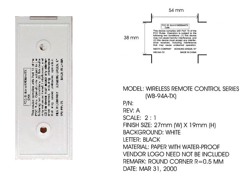
- Wireless Door Chime
- Frequency Range
- 315.00000000 - 315.00000000
- Company
- HeathCo LLC
- Country
- United States
Documents & Files
Document Text
Text extracted from the exhibit documents filed with the FCC. Open a document above to read the original.
Users Manual
PRELIMINARY Wireless Accessory Doorbell Button SL-6190 Series The Heath/Zenith Wireless Accessory Doorbell Button works with existing U, V, W channel or Heath/Zenith jumper or dip switch doorbells. • Battery powered transmitter- No wires to run. • Channels are selectable to allow more than one doorbell set in the same house. © 2000 Heath Co., a Div. of DESA International595-5507-07 -2- 2. Set the doorbell button jumpers to match the chime receiver channel. This button works with channel U, V or W or jumper and dip switch receivers. The doorbell button is ready to use for channel "U". 1. Open the transmitter button case. Insert a flat blade screw driver into notch on bottom, push in on the tab, and twist the screwdriver. Heath/Zenith reserves the right to discontinue and to change specifications at any time without notice without incurring any obligation to incorporate new features in previously sold products. -3- Set the jumpers 1 thru 7 to match the chime receiver. For receivers with switches: jumper on for switch up, jumper off for switch down. For channels V or W insert the jumpers shown below. For chimes with front and backdoor sounds, insert doorbell button jumper 8 for back door sound, remove jumper 8 for front door sound. Bottom of Open Doorbell Button "U" "V" "W" 1 2 3 4 5 6 7 8 Channel Jumper Settings Front/Back Door -4- 4. Mount the Button. Snap the front of button back onto the case. The button can be mounted by using the 2 holes in the back of the case, or double sided tape can be used. If the chime doesn't sound when you press the doorbell button, see page 6 for troubleshooting. 3. Before mounting, test the doorbell range by holding the button where you want to mount it and pressing the doorbell button. -5- Battery Replacement Remove back cover and old battery. Replace with an alkaline type A23 12 V battery. The positive terminal should be at the top of the case. Regulatory Information The user is cautioned that changes or modifica- tions not expressly approved by the party responsible for regulatory compliance could void the user's authority to operate the equipment. This device complies with RSS-210 of Industry Canada. Operation is subject to the following two conditions: (1) this device may not cause harmful interference, and (2) this device must accept any interference received, including interference that may cause undesired operation. -6- Chime doesn't sound: • Make sure the doorbell button and the chime channels are the same (See page 3). • Check orientation of doorbell button battery. • Check the doorbell button and chime batteries, replace if necessary. Batteries are OK, but the chime doesn't work: • Don't mount the chime or doorbell button on metal or near metal studs. This reduces the transmitter range. Use 1/4" to 1/2" wood shims to move the chime or doorbell button off the metal surface. • Don't mount the chime too close to ground level concrete slabs. This may also reduce the range. Mount the chime away from the floor. • Try different locations for the chime closer to the doorbell button. Also try to orient the chime at a different angle to increase the range. The range of the doorbell depends on location, tempera- ture and battery condition. If you are having problems with this product, please try the solutions listed below. If you continue to have problems, consult your warranty. Troubleshooting -7- YOUR HEATH/ZENITH FIVE YEAR LIMITED WARRANTY This is a "Limited Warranty" which gives you specific legal rights. You may also have other rights which vary from state to state or province to province. For a period of five years from the date of purchase, any malfunction caused by factory defective parts or workmanship will be corrected at no charge to you. Batteries are not covered. To obtain a refund or a replacement, return the product to the place of purchase. Not Covered - Repair service, adjustment and calibration due to misuse, abuse or negligence, light bulbs and other expendable items are not covered by this warranty. Unauthorized service or modification of the product or of any furnished component will void this warranty in its entirety. This warranty does not include reimbursement for incon- venience, installation, setup time, loss of use, or unauthorized ser- vice. This warranty covers only Heath/Zenith assembled products and is not extended to other equipment and components that a customer uses in conjunction with our products. This warranty is expressly in lieu of all other warranties, express or implied, including any warranty, representation or condition of merchant ability or that the products are fit for any particular purpose or use, and specifically in lieu of all special, indirect, incidental, or consequential damages. Repair or replacement shall be the sole remedy of the customer and there shall be no liability on the part of heath for any special, indirect, incidental, or consequential damages, including but not limited to any loss of business or profits, whether or not foreseeable. Some states or provinces do not allow the exclusion or limitation of incidental or consequential damages, so the above limitation or exclusion may not apply to you. Retain receipt for warranty claims.
Attestation Statements
A UTHORITY T O A CT A S A GENT I appoint KTL, Ottawa Inc., to act as agent in the preparation of this application for equipment authorization of BJ4 – 61WDB94ATX on our behalf to the Federal Communications Commission. I certify that the Exhibits submitted properly describe the device or system for which equipment authorization is sought. I also certify that each unit manufactured, imported or marketed, as defined in the Commission’s regulations, will have affixed to it a label identical to that submitted for approval with this application. The applicant certifies that neither the applicant nor any party to the application is subject to a denial of Federal benefits, that include FCC benefits, pursuant to Section 5301 of the Anti-Drug Abuse Act of 1988, 21 U.S.C. §862, because of a conviction for possession or distribution of a controlled substance. See 47 CFR 1.2002(b) for the definition of a “party” for these purposes. Dated this day of , 200 . By: x . Randall K. Broome . Original SignaturePrinted Title: Sr. Project Engr. – Mgr. Telephone 270-781-9600 . . Applicant: Heath Company, a division of DESA International (BJ4-).
Cover Letter(s)
Offices In Hull (UK), Ottawa (Canada), Dallas (USA) And Arnhem (The Netherlands) May 10, 2000 Federal Communications Commission Equipment Authorization Branch 7435 Oakland Mills Road Columbia, Maryland 21046 USA KTL 3325 River Road RR #5 Ottawa, Ontario Canada K1V 1H2 Tel: 613-737-9680 Fax: 613-737-9691 Toll Free: 1-800-563-6336 Email: [email protected] Internet: www.ktl.com Dear Sir/Madam:Our File Ref. 0R02235 FCC ID: BJ4-61WDB94ATX Applicant: Heath Company, A div. of DESA Int’l Inc. Equipment: Wireless Door Chime FCC Confirmation no.: EA97551 We have successfully electronically filed all the required documentation for an application for certification in accordance with FCC Part 15 on the above mentioned equipment, May 10, 2000. Enclosed, please find a cheque in the amount of $940.00 US, a copy of FCC Remittance Form 159, a copy of the FCC Form 731 confirmation number and a copy of the list of exhibits. If you require additional information, please do not hesitate to contact me at 1-800-563-6336 (extension 232). Thank you in advance for your assistance in this matter. Sincerely, Ruby Dulmage Regulatory Submissions Clerk KTL Ottawa Inc. [email protected] Encl.
Operational Description
Applicant: Heath Company, a Division of DESA International Inc. 2701 Industrial Dr. Bowling Green, KY. 42102 Manufacturing Location: Heath Company LTD. Rm. 704 Star Centre 443-451 Castle Peak Rd. Kwai Chung, Hong Kong Circuit Description The WB-94A-TX is a Wireless Remote Doorbell Transmitter designed to operate Heath Zenith door chimes receivers in the SL/CL series of AC (plug-in) or battery powered models. These wireless systems consist of the -615x, -616x, -617x and –618x series of products. The WB-94A-TX will also be packaged as a stand-lone accessory and case style may vary, including the push button that covers the power switch. A type-23A, 12V battery powers the transmitter and is included with the product. The transmitter is normally in a powered-down state (stand-by current is zero) until the operator presses a switch to activate the unit. This switch is a front cover push button (momentary contact) that supplies power to the circuit as long as the button is pressed. When the button is released, power is removed and the transmission is stopped. The 12- volt supply (from the battery) is regulated to 5.6 volts by an integral regulator of a custom IC used to encode functions and control the “rf” generator stage. This custom IC is similar to the HT-12E encoder used in the previously certified version (SL-6194-TX) and produces a serial bit stream that corresponds to the state of its address and data control lines. The data rate is approximately 1 kHz and the pattern consists of 8 address bits, 4 data bits and 1 “start” bit (a 13 bit information block). The logic data high bit (one) is represented by a 600 uS pulse-width and a logic low bit (zero) by a 300 uS pulse-width. A minimum of four 13 bit information blocks are sent (transmitted) each time the push button is pressed and will repeat while the switch is held down. A jumper installed in a pin-header that is connected to the IC electrically sets the address and data control bits. When a jumper plug is not installed, the data line floats (pulled high by the internal structure of the IC) and the bit is set at a logic zero. The output of the custom encoder IC (U1) drives the base of the “ rf” oscillator transistor, Q1 and is factory adjusted to 315 MHz by capacitor “VC”. The “rf” is activated when U1’s output is set at a logic high and deactivated when set at logic low. There is no external antenna, transmission radiation comes from a special PCB trace (circuit board foil) and a small internally mounted loop (L1). Alignment There are no user accessible adjustments. During manufacture, adjusting the tuning capacitor “VC” to 315 MHz sets the carrier frequency. Serv ice There are no user serviceable parts in this product. List of Generated Frequencies 315 MHz “rf” oscillator stage 120 kHz digital encoding stage Modulation: digital data, AM pulse-width coding.
Parts List/Tune Up Info
WB-94A-TX Parts List . (PCB level) . WB-94A-TX and WB-97-TX BOMs revised: 17-Apr-00 Component Description ID Tot Qty Comments Printed Circuit Board CEM-1, 1-sided, 1oz Cu. -- 1 Antenna/PCB PCB trace (foil loop) L1* # part of PCB Diodes Rect-signal, 1N4148, D1 1 Capacitors Ceramic, 0.1uF, Y5V, 25V, radial C1 1 Ceramic, 2.2pF, NPO, 50V, radial C2 1 Ceramic, 5.6pF, 50V, 20%, radial C3 1 Ceramic, 20pF, NPO, 50V, radial C4 1 Ceramic, 4.7pF, NPO, 50V, radial C5 1 Ceramic, 47pF, NPO, 50V, radial C6 1 Ceramic, 2pF, NPO, 50V, radial C7 1 Trim (var) -screw, 2 to 5 pF, 20% C8 ("VC") 1 radial, 3-leg Inductors (coils) Coil, Wound, 1.5uH, axial L1 1 Machine formed Resistors Carbon, 1/8W, 5%, 560K ohm R1 -- not used, sets voltage Carbon, 1/8W, 5%, 1M ohm R2 -- not used, sets voltage Carbon, 1/8W, 5%, 1.8M ohm R3 1 Carbon, 1/8W, 5%, 56K ohm R4 1 Carbon, 1/8W, 5%, 27K ohm R5 1 Carbon, 1/8W, 5%, 22 ohm R6 1 DESA International Confidential Prepared By: RKBroome Page 1 WB-94A-TX Parts List . (PCB level) . WB-94A-TX and WB-97-TX BOMs revised: 17-Apr-00 Component Description ID Tot Qty Comments ICs Digital-CMOS, Custom--ROCO U1 1 14pin COB --(similar to Holtec-HD12E) Transistors Bipolar, Hi-freq, 2SC1923Y Q2 1 TO-92 Misc. Battery clip, Positive, Spring steel +BC 1 Battery contact terminals Battery clip, Negative, Spring steel -BC 1 Battery contact terminals Battery, Alkaline, 12 V, type-A23 Batt 1 Switch-Dimple, momentary, sm Sw1 1 Header, 8-pin Dual, plastic PH1 1 Jumper plug, 2-pin, plastic JPx 1--8 any combination from 1 to 8 (used to set channel codes) DESA International Confidential Prepared By: RKBroome Page 2
Test Report
Master: ktlPT15231 Date: April 5, 2000 KTL Test Report:0R02235 Applicant:Heath Company, A Division of Desa Int. PO Box 9004, 2701 Industrial Drive Bowling Green, KY 42102-9004 USA Equipment Under Test:WB-94A-Tx (E.U.T.)Wireless Door Chime FCC ID:BJ4-61WDB94ATX In Accordance With:FCC Part 15, Subpart C For Low Power Transmitters Operating Periodically In The Band 40.66 - 40.77 MHz And Above 70 MHz Tested By:KTL Ottawa Inc. 3325 River Road, R.R. 5 Ottawa, Ontario K1V 1H2 Authorized By: K. Carr, Technologist Date: Total Number of Pages:19 KTL Ottawa FCC PART 15, SUBPART C FOR LOW POWER TRANSMITTERS PROJECT NO.: 0R02235 EQUIPMENT: WB-94A-Tx Wireless Door Chime FCC ID: BJ4-61WDB94ATX Page 2 of 17 Table of Contents Section 1. Summary of Test Results.......................................................................................... 3 Section 2. Equipment Under Test (E.U.T.) .............................................................................. 5 Section 3. Transmission Requirements .................................................................................... 9 Section 4. Radiated Emissions................................................................................................. 11 Section 5. Occupied Bandwidth.............................................................................................. 13 Section 6. Block Diagrams.......................................................................................................15 Section 7. Test Equipment List ............................................................................................... 17 Annex A Restricted Bands.................................................................................................... A1 KTL Ottawa FCC PART 15, SUBPART C FOR LOW POWER TRANSMITTERS PROJECT NO.: 0R02235 EQUIPMENT: WB-94A-Tx Wireless Door Chime FCC ID: BJ4-61WDB94ATX Page 3 of 17 Section 1.Summary of Test Results General All measurements are traceable to national standards. These tests were conducted on a sample of the equipment for the purpose of demonstrating compliance with Part 15, Subpart C, Paragraph 15.231. All tests were conducted using measurement procedure ANSI C63.4-1992. Radiated emissions are made on an open area test site. A description of the test facility is on file with the FCC. New SubmissionProduction Unit Class II Permissive ChangePre-Production Unit DS C Equipment Code THIS TEST REPORT RELATES ONLY TO THE ITEM(S) TESTED. THE FOLLOWING DEVIATIONS FROM, ADDITIONS TO, OR EXCLUSIONS FROM THE TEST SPECIFICATIONS HAVE BEEN MADE. See “ Summary of Test Data”. NVLAP LAB CODE: 100351-0 It is recommended that the margin of compliance be improved to allow for manufacturing tolerances. TESTED BY: _____________________________________ DATE: ___________________ Russell Grant, Wireless Group Manager KTL Ottawa Inc. authorizes the above named company to reproduce this report provided it is reproduced in its entirety and for use by the company’s employees only. Any use which a third party makes of this report, or any reliance on or decisions to be made based on it, are the responsibility of such third parties. KTL Ottawa Inc. accepts no responsibility for damages, if any, suffered by any third party as a result of decisions made or actions based on this report. This report applies only to the items tested. KTL Ottawa FCC PART 15, SUBPART C FOR LOW POWER TRANSMITTERS PROJECT NO.: 0R02235 EQUIPMENT: WB-94A-Tx Wireless Door Chime FCC ID: BJ4-61WDB94ATX Page 4 of 17 Summary Of Test Data Name of TestPara. NumberResults Transmission Requirements15.231(a)Complies Radiated Emissions15.231(b)Complies Occupied Bandwidth15.231(c)Complies Frequency Tolerance15.231(d)Not Applicable Periodic Alternate Field Strength Requirements15.231(e)Not Applicable Powerline Conducted Emissions15.207Not Applicable Test Conditions: Indoor Temperature: 22 °C Humidity:25 % Outdoor Temperature: 21 °C Humidity:25 % KTL Ottawa FCC PART 15, SUBPART C FOR LOW POWER TRANSMITTERS PROJECT NO.: 0R02235 EQUIPMENT: WB-94A-Tx Wireless Door Chime FCC ID: BJ4-61WDB94ATX Page 5 of 17 Section 2.Equipment Under Test (E.U.T.) General Equipment Information Manufacturer: Heath Company, A Division of Desa Int. Model No.: WB-94A-TX Serial No.: None Date Received In Laboratory: May 4, 2000 KTL Identification No.: Item #1 & 2 Frequency Range: 315 MHz Operating Frequency(ies) of Sample: 315 MHz Type of Emission: Pulse Width Modulation Emission Designator: 92K0L1D Supply Power Requirement: Batteries Duty Cycle Calculation: 20 Log 100 6.0134 xx = -10.1 dB KTL Ottawa FCC PART 15, SUBPART C FOR LOW POWER TRANSMITTERS PROJECT NO.: 0R02235 EQUIPMENT: WB-94A-Tx Wireless Door Chime FCC ID: BJ4-61WDB94ATX Page 6 of 17 KTL Ottawa FCC PART 15, SUBPART C FOR LOW POWER TRANSMITTERS PROJECT NO.: 0R02235 EQUIPMENT: WB-94A-Tx Wireless Door Chime FCC ID: BJ4-61WDB94ATX Page 7 of 17 4 Complete Bursts In 100 ms 13 Bits Per Burst 0.6 ms Maximum On Time Per Bit. Maximum On Time = 4x13x0.6 = 31.2 ms KTL Ottawa FCC PART 15, SUBPART C FOR LOW POWER TRANSMITTERS PROJECT NO.: 0R02235 EQUIPMENT: WB-94A-Tx Wireless Door Chime FCC ID: BJ4-61WDB94ATX Page 8 of 17 KTL Ottawa FCC PART 15, SUBPART C FOR LOW POWER TRANSMITTERS PROJECT NO.: 0R02235 EQUIPMENT: WB-94A-Tx Wireless Door Chime FCC ID: BJ4-61WDB94ATX Page 9 of 17 Section 3.Transmission Requirements Para. No.: 15.231(a) Test Performed By: Russell Grant Date of Test: May 5, 2000 Minimum Standard: 15.231(a) Continuous transmissions such as voice, video or data transmissions are not permitted. 15.231(a)(1) A manually operated transmitter shall employ a switch that will automatically deactivate the transmitter within not more than 5 seconds after being released. 15.231(a)(2) A transmitter activated automatically shall cease transmission within 5 seconds of activation. 15.231(a)(3) Periodic transmissions at regular pre-determined intervals are not permitted. However polling or supervisory transmissions to determine system …
Text truncated - open the document above for the full version.
Contact Information
Applicant
Jeff Bessinger(Associate Regulatory Engineer)
Technical Contact
Non-Technical Contact
KTL Ottawa Inc.Ruby C Dulmage
800-563-6336
Test Firm
Nemko Canada Inc.Stuart Beck
Technical Specifications
| # | Rule Parts | Frequency Range | Power Output |
|---|---|---|---|
| 1 | 15C | 315 MHz - 315 MHz | - |
Other Applications from HeathCo LLC

BJ4-9309
Apr 01, 2020Connected LED video security motion light
Equipment Class
DTS - Digital Transmission System
BJ4-9000
Mar 25, 2020Connected Wired Decorative Motion Light
Equipment Class
DTS - Digital Transmission System
BJ4-WLTRX9600
Jan 05, 2020Video Doorbell with 2.4GHz wifi
Equipment Class
DTS - Digital Transmission System
BJ4-WLTX204
Jul 19, 2015Wireless Doorbell extender Kit
Equipment Class
DSC - Part 15 Security/Remote Control Transmitter
BJ4-WLTX208
Jul 06, 2015Wireless Door Chime Transmitter
Equipment Class
DSC - Part 15 Security/Remote Control Transmitter