BJ4-64WDB40TXWireless Chime Control
HeathCo LLC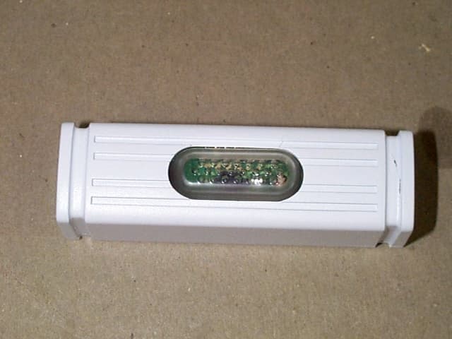
Click to zoom
Application Details
- Equipment Class
- DSC - Part 15 Security/Remote Control Transmitter
- Date of Grant
- Oct 03, 2002
- Application Purpose
- Original Equipment
- Date of Application
- Oct 03, 2002
- Equipment Note
- Wireless Chime Control
- Frequency Range
- 315.00000000 - 315.00000000
- Company
- HeathCo LLC
- Country
- United States
Documents & Files
Document Text
Text extracted from the exhibit documents filed with the FCC. Open a document above to read the original.
Users Manual
DRAFT COPY Lighted Wireless Push Button Accessory The Heath ® /Zenith Wireless Push Button Accessory works with existing Heath ® /Zenith jumper or dip switch systems. •Battery powered push button - No wires to run. •128 selectable codes allow more than one chime system in the same house. •LED lighted push bar in dark conditions. © 2002 DESA International598-1137-00 (Style may vary from illustration) Lighted Push Bar Feature Your Heath ® /Zenith wireless (battery operated) push button contains a LED (Light Emitting Diode) that will turn on in dark conditions so the push button will be more visible for your guests. This patent (pending) technology and built-in photocontrol will allow the light intensity of the push button LED to increase as the outdoor light conditions around the push button decreases. The actual time and intensity that the LED is visible will depend on the specific mounting environment of the push button. In darker environments, such as garages, carports, or covered porches, the LED will be visible a longer period of time each day or always. In very well lighted environments, the LED will be visible for a shorter period of time each day or never. In nominal conditions the bat- teries will typically last 2 years. -2- 598-1137-00 DRAFT COPY 2.Set the push button jumpers to match the chime receiver code. See “Code and Tune Setting” section. 1.Install lithium type CR2032 3 volt batteries (included). Remove back of case by pushing in tab on bottom with a small screwdriver. Make sure battery is oriented properly (see page 5). 4. Mount push button. Use either screws or double sided tape to mount push button. To mount with screws, remove back of case by pushing in tab on bottom with a small screwdriver. Attach back of case to door jamb or wall. Snap front of push button on. When attaching push button using double sided tape, make sure the surface of the door jamb or wall is clean. 3.Test range. Temporarily position push button where you want it mounted. Press push button to verify chime and push button work properly. If chime does not sound, see Troubleshooting. -3- 598-1137-00 DRAFT COPY Code and Tune Settings Code Settings Note: Most installations will not require you to change any jumpers on your chime and push button. WARNING: Disconnect chime unit from power source be- fore opening code access door. Close door and replace screw before reconnecting to power. The push button and chime communicate by using a code that can be changed by removing and/or adding jumpers on both the push button and chime. The code is factory set; however, there are 128 selectable codes that allow you to expand your system and prevent outside interference. Other wireless prod- ucts may cause interference and the system may not function properly. Follow the instructions below for setting a new code. 1. Unplug wireless chime (if applicable). 2. Open the cases and locate the jumpers on both the push but- ton and chime (See illustration on page 5). 3. The push button and chime both have eight different jumper locations. The jumper positions 1 through 7 are used for set- ting the code. 4. To change the code, add and/or remove jumpers as needed. It is recommended to only change one jumper at a time and then check to see if system is functioning properly. Note: Jump- ers in positions 1 through 7 must be exactly the same for both the push button and chime for this system to function. -4- 598-1137-00 DRAFT COPY Tune Settings Your Heath ® /Zenith wireless chime has different selectable tunes: Ding (one note), Ding-Dong (two note), or Westminster (eight note) (Available on selected Heath ® /Zenith chimes). The fac- tory setting is for the Ding-Dong tune (or Westminster, when available). This tune can be changed by following the instruc- tions below. •Ding (one note tune) Push button: Add a jumper to location 8. •Ding-Dong (two note tune) Push button: Remove jumper from location 8. Chime: Remove jumper from location 8. •Westminster (Eight note tune) (Available on selected Heath ® / Zenith chimes) Push button: Remove jumper from location 8. Chime: Add a jumper to location 8. Note: All models have both front and back door tune capabili- ties. You may purchase any Heath ® /Zenith wireless push button for a second entrance. We recommend the back door use the Ding tune and the front door use the Ding-Dong tune (or Westminster tune, available on selected Heath ® /Zenith chimes). Models that include two push buttons will come factory set for front and back doors. Decals on the rear of the push button will indicate its setting. -5- 598-1137-00 DRAFT COPY C R 2 0 3 2 + 1 2 3 4 5 6 7 8 12345678 Inside Push Button Replacing Push Button Batteries Install two lithium type CR2032 3 volt batteries. See diagram inside push button for correct battery orientation. * Code Settings 1-7 Must Match Both Push Button and Chime Remove screw to open access door Tune Setting (Not used on all models) Back of Chime Tune Setting Note: Some models might require the use of tweezers to remove and replace the jumpers. -6- 598-1137-00 DRAFT COPY Troubleshooting Chime does not sound: •Make sure push button and chime codes are the same (See pages 3, 4, and 5). •Check orientation of push button battery (See page 5). •Check charge of push button and chime batteries (if applicable), re- place if necessary. Batteries seem OK, but the chime does not work when installed: •Do not mount chime or push button on metal or near metal studs. This reduces the transmitter range. Use 1/4" to 1/2" (6 to 13 mm) wood shims to move chime or push button off metal surface. •Concrete floors may reduce range. Move chime away from floor. •Try locating chime closer to push button. Push button light (LED) is “ON” or “OFF” all the time (see page 1). The range of the wireless chime can vary with location, temperature and battery condition. -7- 598-1137-00 DRAFT COPY No Service Parts Available for this Product Technical Service (Do Not Send Products) If you experience a problem…
Text truncated - open the document above for the full version.
Cover Letter(s)
Barry Quinlan From: "Ruby Dulmage" <[email protected]> To: "Curtis-Straus TCB" <[email protected]> Sent: Monday, September 30, 2002 1:17 PM Attach: SL-6440-41PCBrear.pdf; SL-6440-41PCBfront.pdf Sub ject: Re: DESA FCC ID: BJ4-64WDB40TX Page 1 of 1 10/4/2002 Hi Barry: 1. Attached are the interior photos. 2. Yes, fresh batteries were used for testing. Thanks, Ruby Ruby Dulmage Submissions Specialist Nemko Canada Inc. 303 River Road, R.R. 5 Ottawa, ON K1V 1H2 Tel: 613-737-9680 ext 232 Fax: 613-737-9691 Email: [email protected] ----- Original Message ----- From: Curtis -Straus TCB To: Ruby Dulmage Sent: Friday, September 27, 2002 5:00 PM Subject: DESA FCC ID: BJ4-64WDB40TX Hi Ruby, We have identified these issues following our review of the application: 1. We do not appear to have any internal photos. 2. Please confirm fresh batteries were used during the testing. Best regards Barry C. Quinlan Certification Manager Curtis-Straus TCB
ID Label/Location Info
DRAFT COPY FCC ID: BJ4-64WDB40TX IC: 3984A-6440TX This device complies with Part 15 of the FCC Rules. Operation is subject to the following two conditions: (1) this device may not cause harmful interference, and (2) this device must accept any interference received, including interference that may cause undesired operation. DESA International, Inc. Bowling Green, KY 6440TX MADE IN CHINA Patent Pending 390-6440-TX1A
Operational Description
Lighted Transmitter Product Description Heath®/Zenith Model number: SL-6440 & SL-6441 FCC Model designation: 6440TX IC #: Canada: 3984A-6440TX SL-6440 (LE-6440) & SL-6441 Description Model SL-6440 (LE-6440) & SL-6441 are wireless lighted transmitters that contain the same PCB and circuit design, which is FCC Model designation 6440TX, with different plastic case designs, color of LED, and/or packaging. Two CR-2032 lithium 3-volt batteries power this unit. This input power is internally regulated in the encoder IC T-99. The pin header is the selector to control the coding for the T-99 encoder. The output of the encoder chip goes through the oscillator/modulator stage. The oscillator is tuned for 315M Hz. The encoded signal is then sent through the “paper clip” antenna mounted on the PCB and the RF output is transmitted into the air. A photo resistor, super bright LED, and biasing circuit operates independently from the RF circuitry to provide light in dark conditions.
Parts List/Tune Up Info
Unit NEW PARTLED NICHIA NSPB320BSLED NEW PARTCDS HEIMANN A906034CDS 417-0875TRANSISTOR 2N3904 085-P154PCB 204-2947BATTERY CONTACTpc 204-2379BATTERY CONTACT PINpc 012-P003BATTERY LITHIUM 3V CR2032 pc
Test Report
Master:PT15-Sub-C-15231 Date: November 12, 2001 Test Report:2W06481 Applicant:DESA International 2901 Industrial Drive Bowling Green, KY 42102 Equipment Under Test:Wireless Lighted Chime Control Model 6440TX/6441TX (EUT)315MHz Transmitter FCC ID:BJ4-64WDB40TX In Accordance With:FCC Part 15, Subpart C, 15.231 Tested By:Nemko Canada Inc. 303 River Road, R.R. 5 Ottawa, Ontario K1V 1H2 Authorized By: Glen Westwell, Wireless Technologist Date:23 September 2002 Total Number of Pages:21 Nemko Canada Inc.FCC PART 15, SUBPART C, 15.231 PROJECT NO.:2W06481 EQUIPMENT: 6440/6441TX Wireless Lighted Chime Control Page 2 of 21 Table of Contents Section 1. Summary of Test Results......................................................................................3 Section 2. Equipment Under Test.........................................................................................5 Section 3. Transmission Requirements...............................................................................14 Section 4. Radiated Emissions.............................................................................................16 Section 5. Occupied Bandwidth..........................................................................................19 Section 6. Block Diagrams...................................................................................................19 Section 7. Test Equipment List...........................................................................................21 Nemko Canada Inc.FCC PART 15, SUBPART C, 15.231 PROJECT NO.:2W06481 EQUIPMENT: 6440/6441TX Wireless Lighted Chime Control Page 3 of 21 Section 1.Summary of Test Results General All measurements are traceable to national standards. These tests were conducted on a sample of the equipment for the purpose of demonstrating compliance with Part 15, Subpart C. All tests were conducted using measurement procedure ANSI C63.4-1992. Radiated emissions are made on an open area test site. A description of the test facility is on file with the FCC. THIS TEST REPORT RELATES ONLY TO THE ITEM(S) TESTED. THE FOLLOWING DEVIATIONS FROM, ADDITIONS TO, OR EXCLUSIONS FROM THE TEST SPECIFICATIONS HAVE BEEN MADE. NONE TESTED BY: ______________________________DATE: 20 September 2002 Kevin Carr, EMC Specialist Nemko Canada Inc. authorizes the above named company to reproduce this report provided it is reproduced in its entirety and for use by the company’s employees only. Any use which a third party makes of this report, or any reliance on or decisions to be made based on it, are the responsibility of such third parties. Nemko Canada Inc. accepts no responsibility for damages, if any, suffered by any third party as a result of decisions made or actions based on this report. This report applies only to the items tested. Nemko Canada Inc.FCC PART 15, SUBPART C, 15.231 PROJECT NO.:2W06481 EQUIPMENT: 6440/6441TX Wireless Lighted Chime Control Page 4 of 21 Summary Of Test Data Name of TestPara. NumberResults Transmission Requirements15.231(a) Complied Radiated Emissions15.231(b)Complied Occupied Bandwidth15.231(c)Complied Frequency Tolerance15.231(d)N/A Periodic Alternate Field Strength Requirements15.231(e)N/A Power line Conducted Emissions15.207N/A Notes: This certification is for the 6440TX and the 6441TX 315MHz transmitter. The RF circuitry for both models is identical. Compliance was demonstrated using one sample of the 6440TX model. IndoorTemperature:22°C Humidity:40% OutdoorTemperature:17°C Humidity:65% Nemko Canada Inc.FCC PART 15, SUBPART C, 15.231 PROJECT NO.:2W06481 EQUIPMENT: 6440/6441TX Wireless Lighted Chime Control Page 5 of 21 Section 2.Equipment Under Test General Equipment Information Manufacturer: Desa International Model No.: 6440TX Serial No.: None Date Received In Laboratory: 17 Sept. 2002 Nemko Identification No.: 1 Frequency Range (or fixed frequency): 315MHz -Fixed RF Power in Watts: 0.00000105 Field Strength (distance): 68.0dBuV@3 meters Occupied Bandwidth (99% BW): 108.3kHz Type of Modulation: PCM Emission Designator: 108K3L1D Transmitter Spurious (worst case): 50.8dBuV@630MHz Primary Input Power: Two, CR-2032, Lithium Batteries Duty Cycle Calculation: 20Log{((7*0.34ms+6*0.67ms)*4)/100ms}= -11.8dB Nemko Canada Inc.FCC PART 15, SUBPART C, 15.231 PROJECT NO.:2W06481 EQUIPMENT: 6440/6441TX Wireless Lighted Chime Control Page 6 of 21 Duty Cycle Plots Nemko Canada Inc.FCC PART 15, SUBPART C, 15.231 PROJECT NO.:2W06481 EQUIPMENT: 6440/6441TX Wireless Lighted Chime Control Page 7 of 21 Nemko Canada Inc.FCC PART 15, SUBPART C, 15.231 PROJECT NO.:2W06481 EQUIPMENT: 6440/6441TX Wireless Lighted Chime Control Page 8 of 21 Nemko Canada Inc.FCC PART 15, SUBPART C, 15.231 PROJECT NO.:2W06481 EQUIPMENT: 6440/6441TX Wireless Lighted Chime Control Page 9 of 21 Nemko Canada Inc.FCC PART 15, SUBPART C, 15.231 PROJECT NO.:2W06481 EQUIPMENT: 6440/6441TX Wireless Lighted Chime Control Page 10 of 21 Nemko Canada Inc.FCC PART 15, SUBPART C, 15.231 PROJECT NO.:2W06481 EQUIPMENT: 6440/6441TX Wireless Lighted Chime Control Page 11 of 21 Nemko Canada Inc.FCC PART 15, SUBPART C, 15.231 PROJECT NO.:2W06481 EQUIPMENT: 6440/6441TX Wireless Lighted Chime Control Page 12 of 21 Nemko Canada Inc.FCC PART 15, SUBPART C, 15.231 PROJECT NO.:2W06481 EQUIPMENT: 6440/6441TX Wireless Lighted Chime Control Page 13 of 21 99% Occupied Bandwidth Nemko Canada Inc.FCC PART 15, SUBPART C, 15.231 PROJECT NO.:2W06481 EQUIPMENT: 6440/6441TX Wireless Lighted Chime Control Page 14 of 21 Section 3.Transmission Requirements Para. No.: 15.231(a) Test Performed By: Kevin CarrDate of Test: 17 Sept. 2002 Minimum Standard:15.231(a) Continuous transmissions such as voice, video or data transmissions are not permitted. 15.231(a)(1) A manually operated transmitter shall employ a switch that will automatically deactivate the transmitter within not more than 5 seconds after being released. 15.231(a)(2) A transmitter activated automatically shall cease transmission within 5 seconds of activ…
Text truncated - open the document above for the full version.
Contact Information
Applicant
Jeff Bessinger(Associate Regulatory Engineer)
Test Firm
Nemko Canada Inc.Stuart Beck
Technical Specifications
| # | Rule Parts | Frequency Range | Power Output |
|---|---|---|---|
| 1 | 15.231 | 315 MHz - 315 MHz | - |
Other Applications from HeathCo LLC

BJ4-9309
Apr 01, 2020Connected LED video security motion light
Equipment Class
DTS - Digital Transmission System
BJ4-9000
Mar 25, 2020Connected Wired Decorative Motion Light
Equipment Class
DTS - Digital Transmission System
BJ4-WLTRX9600
Jan 05, 2020Video Doorbell with 2.4GHz wifi
Equipment Class
DTS - Digital Transmission System
BJ4-WLTX204
Jul 19, 2015Wireless Doorbell extender Kit
Equipment Class
DSC - Part 15 Security/Remote Control Transmitter
BJ4-WLTX208
Jul 06, 2015Wireless Door Chime Transmitter
Equipment Class
DSC - Part 15 Security/Remote Control Transmitter