BJ4-64WDB46TXWireless button
HeathCo LLC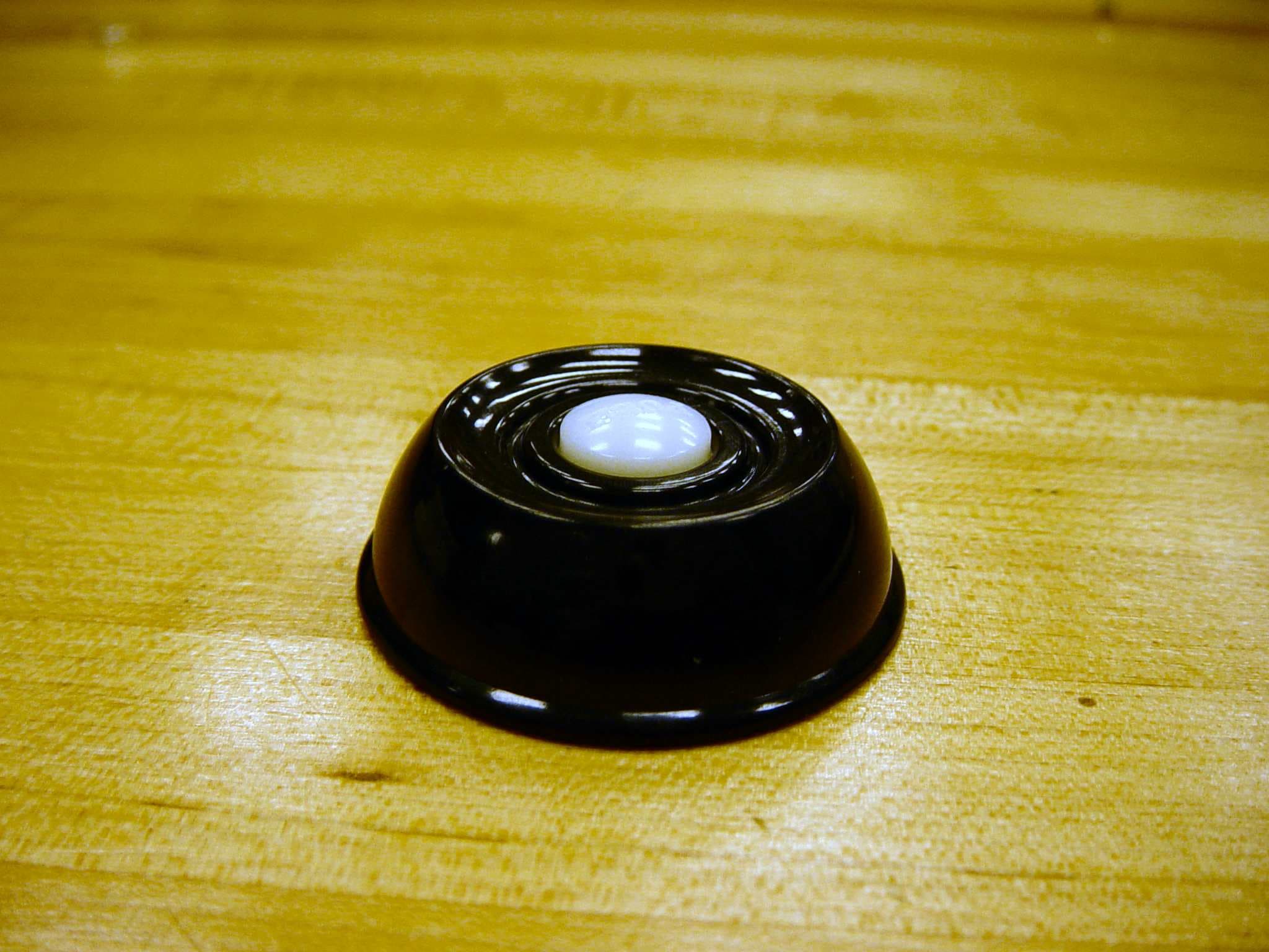
Click to zoom
Application Details
- Equipment Class
- DSC - Part 15 Security/Remote Control Transmitter
- Date of Grant
- Jan 13, 2010
- Application Purpose
- Original Equipment
- Date of Application
- Jan 11, 2010
- Equipment Note
- Wireless button
- Frequency Range
- 315.00000000 - 315.00000000
- Company
- HeathCo LLC
- Country
- United States
Documents & Files
Document Text
Text extracted from the exhibit documents filed with the FCC. Open a document above to read the original.
Users Manual
Wireless Push Button Accessory The Heath ® /Zenith Wireless Push Button Ac- cessory works with any Heath ® /Zenith wireless chime. • Patented Technology - Select models only. • Battery powered push button - No wires to run. • 128 selectable codes allow more than one chime system in the same house. • Factory installed batteries. • LED halo lighted push button - Select models only (see Halo Lighted Push Button Feature for more information). © 2009 HeathCo LLC 598-1105-08 (Style may vary from illustration) -2- 598-1105-08 Pull tab to activate batteries Figure 1 WARNING: To prevent possible SERIOUS INJURY or DEATH: • NEVER allow small children near batteries. • If battery is swallowed, immediately notify doctor. 1. Remove back of push button. To remove back of push button, push in tab on bottom with a small screwdriver (see Figure 1). Pull battery tab to acti- vate factory installed batteries. Note: See Trouble- shooting for replacement battery information. 2. Test range. Temporarily position push button where you want it mounted. Press push button to verify chime and push button work properly. If chime does not sound, see Troubleshooting. 3. Mount push button. Use either screws or double sided tape to mount push button. • Screw Mounting: To mount with screws, re- move back of case by pushing in tab on bottom with a small screwdriver (see Figure 1). Note: Remove material in screw holes (if needed) before mounting with screws. Attach back of case to door jamb or wall (see Figure 2). Snap front of push button on. • Tape Mounting: When attaching push button using double sided tape, make sure the surface of the door jamb or wall is clean. (Tape available for select models only.) Figure 2 -3- 598-1105-08 ON 1 2 3 4 5 6 7 8 C h i m e V o l u m e 1 2 3 4 5 6 7 8 Tune Settings Your wireless chime has different selectable tunes: Ding (one note), Ding-Dong (two note), or Westmin- ster (eight note) (Available on selected chimes). The factory setting is for the Ding-Dong tune (or Westmin- ster, when available). This tune can be changed by following the instructions below. • Ding (one note tune) Inside Push Button: Location 8, set dip switch ON (1 or High) or add jumper. • Ding-Dong (two note tune) Inside Push Button: Location 8, set dip switch OFF (0 or Low) or remove jumper. Chime: Remove jumper from location 8. • Westminster (Eight note tune) (Available on selected chimes) Inside Push Button: Location 8, set dip switch OFF (0 or Low) or remove jumper. Chime: Add a jumper to location 8. Note: All models have both front and back door tune capabilities. We recommend the back door use the Ding tune and the front door use the Ding-Dong tune (or Westminster tune, available on selected chimes). Note: Some models might require the use of tweezers to remove and replace the jumpers. Figure 3 Inside Push Button Chime Tune Setting (Not used on all models) Tune Setting -4- 598-1105-08 1 2 3 4 5 6 7 8 O N 1 2 3 4 5 6 7 8 ON + (+) Positive Battery Terminal Insert Batteries (+) Positive Side Up Troubleshooting A. Chime does not sound: • Make sure push button and chime codes are the same (see Figure 5). • Check orientation of push button batteries (See inside back cover of push button for correct battery orientation). • Check charge of push button and chime batteries (if applicable), replace if necessary. B. Chime sounds when not intended (false triggers): Chime is receiv- ing interference from another wireless device; change the code setting (see Code Setting below). C. Batteries seem OK, but the chime does not work when installed: • Do not mount chime or push button on metal or near metal studs. This reduces the transmitter range. Use 1/4" to 1/2" (6 to 13 mm) wood shims to move chime or push button off metal surface. • Concrete floors may reduce range. Move chime away from floor. • Try locating chime closer to push button. Figure 4 - Inside Push Button Note: See inside back cover of push button for battery size (CR 1220 or CR 2032), orientation, and quantity. -5- 598-1105-08 D. Push button light (LED) is “ON” or “OFF” all the time (see Halo Lighted Push Button Feature). E. Code Setting: It is recommended to only change one code position at a time and then check to see if system is functioning properly. 1. Open the cases and locate the dip switches or jumpers on both the push button and chime (see Figure 5). 2. The push button and chime both have eight different dip switch or jumper locations. Positions 1 through 7 are used for setting the code. 3. To change the code, either: • Add a jumper to the chime and set the matching push button dip switch to ON or... • Remove a jumper from the chime and set the matching push button dip switch to OFF or... C h i m e V o l u m e 12345678 Inside Push Button Chime Figure 5 ON 1 2 3 4 5 6 7 8 * Code Settings 1-7 Must Match Both Push Button and Chime Continued Note: Some models might require the use of tweezers to remove and replace the jumpers or a small screw driver to set dip switches. -6- 598-1105-08 Halo Lighted Push Button Feature (Select Models Only) This Heath ® /Zenith wireless push button contains a LED (Light Emitting Diode) that lights up in the dark making the push button more visible for your guests. This patented technology and built-in photocontrol (light sen- sor) allows the brightness of the LED to increase as the lighting around the push button decreases. The LED may stay ON or OFF longer than normal if the push button is mounted in an area that is too dark or too bright. In normal conditions, the batteries will typically last 1 year. • Move a jumper on the chime from one location to another. Set the matching two dip switches on the push button to match the jumper settings on the chime. Example: In the chime, move the chime jumper at location “5” to location “4”. In the push button, set the “5” dip switch to OFF and the “4” dip switch to ON. Note: Code positions 1 through 7 must be exactly the same for both the push button and chime for this system to function. …
Text truncated - open the document above for the full version.
Cover Letter(s)
DATE 12-15-2009 Equipment Autorisation Division Federal Communications Commission 7435 Oakland Mills Road Columbia, MD 21046 FCC ID:_ BJ4-64WDB46TX ___ Product Name:__ Wireless Door Chime Button WB-6446-TX Request for Confidentiality Pursuant to Sections 0.457 and 0.459 of the commissions rules, we hereby request that the following documents be held confidential: (List here the documents for which you are seeking confidentiality – for example ...) • Schematics • Block diagram • Operational Description • Parts Lists These materials contain trade secrets and proprietary information and are not customarily released to the public. The public disclosure of this information might be harmful to the company and provide unjustified benefits to our competitors. Dated this 15th Day of December 20 09 By: Jeff Bessinger Signature Printed Title: Associate Engineer On behalf of : HeathCo LLC Telephone: 270-846-8271
Test Report
www.nemko.com Nemko Canada Inc., 303 River Road, R.R. 5, Ottawa, Ontario, Canada, K1V 1H2 Report number: 140821-1TRFWL Apparatus: Door Chime Transmitter (WB-6446-TX) Applicant: HeathCo LLC 2445 Nashville Rd. P.O. Box 90045 Bowling Green, KY 42102 USA FCC ID: BJ4-64WDB46TX Test specification: Title 47-Telecommunication Chapter I - Federal Communications Commission Subchapter A - General Part 15 - Radio Frequency Devices Subpart C - Intentional Radiators §15.231- Periodic operation in the band 40.66–40.70 MHz and above 70 MHz Reviewed by: January 11, 2010 Signature Date Kevin Ma, Wireless/EMC Specialist Tested by: David Duchesne, Wireless/EMC Specialist Nemko Canada Inc. authorizes the applicant to reproduce this report provided it is reproduced in its entirety and for use by the company’s employees only. Any use which a third party makes of this report, or any reliance on or decisions to be made based on it, are the responsibility of such third parties. Nemko Canada Inc. accepts no responsibility for damages, if any suffered by any third party as a result of decisions made or actions based on this report. This report shall not be reproduced except in full without the written approval of the testing laboratory. Nemko Canada Inc., a testing laboratory, is accredited by the Standards Council of Canada. The tests included in this report are within the scope of this accreditation. Report Number: 140821-1TRFWL Nemko Canada Inc., 303 River Road, R.R. 5, Ottawa, Ontario, Canada, K1V 1H2 Specification: FCC 15.231 Page 2 of 20 Table of contents Title 47-Telecommunication..................................................................................................................2 Section 1: Report summary.....................................................................................................................3 Section 2: Equipment under test.............................................................................................................4 2.1 Identification of equipment under test (EUT)...............................................................................4 2.2 EUT description...........................................................................................................................4 2.3 Technical specifications of the EUT............................................................................................4 2.4 EUT setup diagram.....................................................................................................................5 2.5 Operation of the EUT during testing............................................................................................5 2.6 Modifications incorporated in the EUT........................................................................................5 Section 3: Test conditions.......................................................................................................................6 3.1 Deviations from laboratory tests procedures...............................................................................6 3.2 Test conditions, power source and ambient temperatures..........................................................6 3.3 Measurement uncertainty............................................................................................................7 3.4 Test equipment............................................................................................................................7 Section 4: Result summary......................................................................................................................8 4.1 FCC Part 15 Subpart C, 15.231: Test results..............................................................................8 Appendix A: Test results..........................................................................................................................9 Clause 15.31(e) Variation of the power source..................................................................................9 Clause 15.203 Antenna requirement..................................................................................................9 Clause 15.231(a) Conditions for intentional radiators to comply with periodic operation ((1) Manually operated transmitter) ............................................................................................................10 Clause 15.231(b) Field strength of emissions..................................................................................12 Clause 15.231(c) Emission bandwidth.............................................................................................18 Appendix B: Block diagrams of test set-ups........................................................................................20 Section 1: Report summary Report Number: 140821-1TRFWL Nemko Canada Inc., 303 River Road, R.R. 5, Ottawa, Ontario, Canada, K1V 1H2 Specification: FCC 15.231 Page 3 of 20 Section 1: Report summary These tests were conducted on a sample of the equipment for the purpose of demonstrating compliance with Part 15, Subpart C. Radiated tests were conducted in accordance with ANSI C63.4-2009 and ANSI C63.10 procedures. This report contains an assessment of apparatus against specifications based upon tests carried out on samples submitted at Nemko Canada Inc. Test specification: FCC Part 15 Subpart C, 15.231 Periodic operation in the band 40.66–40.70 MHz and above 70 MHz. Compliance status: Complies Exclusions: None Non-compliances: None Report release history: Original release Test location: Nemko Canada Inc. 303 River Road, R.R. 5, Ottawa, Ontario, Canada, K1V 1H2 Registration number: 176392 (3 m Semi anechoic chamber) Note that the results contained in this report relate only to the items tested and were obtained in the period between the date of initial receipt of samples and the date of issue of the report. This test report has been completed in accordance with the requirements of ISO/IEC 17025. All resu…
Text truncated - open the document above for the full version.
Test Setup Photos
Nemko Canada Inc., 303 River Road, R.R. 5, Ottawa, Ontario, Canada, K1V 1H2 Setup Photos
Contact Information
Applicant
Jeff Bessinger(Associate Regulatory Engineer)
Technical Contact
HeathCo LLCJeff Lane Bessinger
[email protected]270-846-8271
2445 Nashville road · Bowling Green, Kentucky · United States
Non-Technical Contact
HeathCo LLCJeff Lane Bessinger
[email protected]270-846-8271
Test Firm
Nemko Canada Inc. (Ottawa)Charles Neal
Technical Specifications
| # | Rule Parts | Frequency Range | Power Output |
|---|---|---|---|
| 1 | 15.231 | 315 MHz - 315 MHz | - |
Other Applications from HeathCo LLC

BJ4-9309
Apr 01, 2020Connected LED video security motion light
Equipment Class
DTS - Digital Transmission System
BJ4-9000
Mar 25, 2020Connected Wired Decorative Motion Light
Equipment Class
DTS - Digital Transmission System
BJ4-WLTRX9600
Jan 05, 2020Video Doorbell with 2.4GHz wifi
Equipment Class
DTS - Digital Transmission System
BJ4-WLTX204
Jul 19, 2015Wireless Doorbell extender Kit
Equipment Class
DSC - Part 15 Security/Remote Control Transmitter
BJ4-WLTX208
Jul 06, 2015Wireless Door Chime Transmitter
Equipment Class
DSC - Part 15 Security/Remote Control Transmitter