BJ4-WRC6032TXOutdoor Wireless Motion Sensor
HeathCo LLC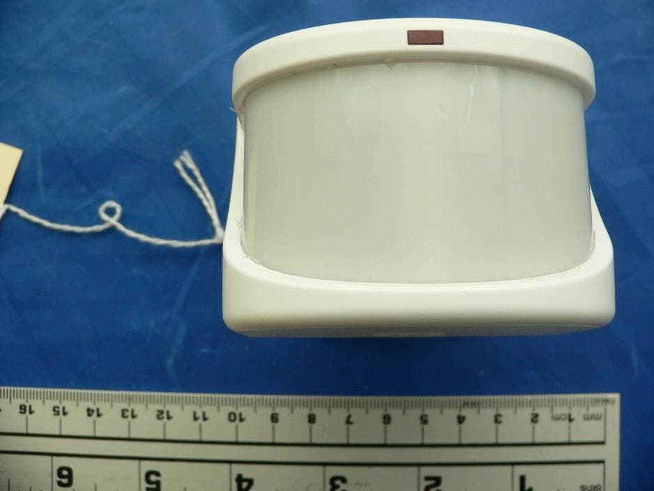
Click to zoom
Application Details
- Equipment Class
- DSC - Part 15 Security/Remote Control Transmitter
- Date of Grant
- May 28, 2007
- Application Purpose
- Original Equipment
- Date of Application
- May 28, 2007
- Equipment Note
- Outdoor Wireless Motion Sensor
- Frequency Range
- 315.00000000 - 315.00000000
- Company
- HeathCo LLC
- Country
- United States
Documents & Files
Document Text
Text extracted from the exhibit documents filed with the FCC. Open a document above to read the original.
Users Manual
DRAFT COPY ENGLISH © 2007 DESA Specialty Products™ 598-1302-00 Outdoor Wireless Motion Sensor This manual includes operating instructions for a variety of remote controlled products. All products work on the same principle and use the same code setting information. Please read all instructional information and note any specifi c information pertaining to your particular product. FEATURES • Products are UL/cUL and/or FCC/IC tested and approved. • Operational range of up to 100 feet. Heath ® /Zenith wireless lighting controls are designed to work together. Simply determine which transmitter(s) you would like to have control which receiver(s) and set the code setting to match. CODE SETTINGS Note: Most single system installations will not require any change to the code setting. Transmitter(s) and receiver(s) must have the same code and group setting to work together. Switches 1 through 3 set the code. Switch 4 sets the Group (A or B). See page 2 for switch locations. Transmitter(s)/ Receiver(s) Code Group “B” Example 1 - Code Settings, System 1 (Factory Setting) Transmitter(s)/ Receiver(s) Code Group “A” ( – Indicates Position of Switch) Example 2 - Code Settings, System 2 Note: When operating more than one system independently of each other, set each system to a different code. There are 8 codes avail- able by changing the settings of switches 1 through 3. Transmitter(s)/ Receiver(s) Code Group “A” 2598-1302-00 DRAFT COPY CODE SWITCH LOCATIONS Outdoor Wireless Motion Sensor Code Switches DETECTCODES 1 2 3 4 DAY NIGHT NIGHT ONLY ON 1 2 3 4 Close-Up of Typical Code Switch (Factory Default Setting is Off) Note: The “X” has been placed on the switches to help clarify the code settings on the previous page. 3598-1302-00 ENGLISH DRAFT COPY DETECTCODES 1 2 3 4 DAY NIGHT NIGHT ONLY Detect Control Battery Compartment INDOOR AND OUTDOOR WIRELESS MOTION SENSOR Features: • No wiring required. • Up to 70 feet sensing range, 180° Coverage (Outdoor). • Adjustable sensitivity. • Day/Night or Night only operation. • Test mode. • Uses 2 AA batteries. • Wall or eave mount (Outdoor). • Controls receivers up to 100 feet away. Outdoor Wireless Motion Sensor Outdoor Motion Sensor (Rear View) Select Night or 24 Hour Mode These sensors are able to detect motion day and night or night only. To set the detection mode, remove battery compartment cover by sliding the cover down. Remove batteries if necessary. Slide the DETECT switch to either the DAY/NIGHT or NIGHT ONLY position. Replace battery compartment cover by reversing the above instructions. Installing Batteries Note: Before mounting outdoor motion sensor, remove battery compartment cover by sliding the cover down. Install 2 AA batteries according to polarity markings inside the battery compartment. Replace battery compartment cover by reversing the above instructions. Continued Installing Motion Sensor Mounting Bracket Clamp Screw Nut Sensor Mounting Screw Swivel Ball Mount Mounting Bracket Socket Installing Outdoor Motion Sensor 1. Install sensor mounting bracket where motion detection is desired. Attach sensor mounting bracket to a sturdy object (i.e. tree, post, house, etc.) using two screws provided. Make sure unit has an unobstructed view. Note: Attach mounting bracket vertically if connecting to a curved surface such as a post. 2. Install motion sensor to mounting bracket. Using a Philips-head screwdriver, loosen the clamp screw on the mounting bracket. Insert swivel ball mount on sensor into mounting bracket socket (Note: You should hear a snap). Aim sensor toward area where detection is desired. Tighten clamp screw. IMPORTANT: The sensor must be mounted with the bottom cover facing down in order to maintain water tightness. Check Operation and Adjustment Note: When fi rst turned on or when switching modes wait 30 seconds. Locate the RANGE control and ON-TIME control on the motion sensor: • The RANGE control and ON-TIME control are located on the bottom of the sensor. Using your fi ngernails or a small, fl at-head screwdriver, gently pry the cover until it opens. 1. Check Operation. Set the ON-TIME control to TEST mode. Walk in front of sensor unit. The LED indicator light should fl ash when motion is detected (see illustration, page 8, for location of LED light). 2. Adjust Sensor. Turn the RANGE control to the mid position and ON-TIME control to the TEST position. Walk through coverage area noting where you are when the LED begins to fl ash. Loosen the clamp screw and move the sensor to change the coverage area. Tighten clamp screw when fi nished. Do not overtighten clamp screw. Codes 4598-1302-00 DRAFT COPY Motion Sensor Controls RANGE ON-TIMEDUALBRITE™ MAX DUSK TO DAWN TEST 1 5 (MINS) 3 HRS OFF MIN Range Control D UALBRITE™ ON-TIME Control Motion Sensor Sensitivity The detector is most sensitive to motion across its fi eld of view. Motion Most SensitiveLeast Sensitive Motion SensorSensor Maximum Coverage Angle Maximum Range Motion Sensor Coverage Area 70 ft. (21 m) 8 ft. (2.4 m) 180° Aim Sensor Down for Short Coverage Aim Sensor Higher for Long Coverage Adjusting Motion Sensor Coverage 3. Adjust RANGE Control. To increase sensitivity, turn the RANGE control toward MAX. To decrease sensitivity, turn the RANGE control toward MIN. Note: If the RANGE is set too high, false triggering may result in some environments. Note: When using test mode to check operation in the day time: A. Set the DETECT control switch to DAY/NIGHT and B. Set the ON-TIME control to TEST. 4. Set ON-TIME Control. Determine the amount of time you want the connected device to stay on after motion is detected (1 or 5 minutes). Slide the ON-TIME control to the corresponding setting. IMPORTANT: Avoid Aiming Control At: • Objects that change temperature rapidly, such as heating vents, fans, and air conditioners. These air sources could cause false triggering. • Areas where pets or traffi c may trigger the control. • Nearby large, light colored objects refl ecting light may trigger the sh…
Text truncated - open the document above for the full version.
Block Diagram
REF. No:6032 TX 3V Battery Power RF Encoder SAW (315MHz) Motion Sensor Transmitter Circuit (315 MHz) A ntenna (Coiled Wire, Internal) Transmitter Circuit Block Diagram 5/29/2007 Block Diagram of 6032-TX.xls
Cover Letter(s)
BACL-NF013-C May 14, 2007 To: Bay Area Compliance Laboratories Corp. 1274 Anvilwood Avenue Sunnyvale, CA 94089 Dear Sir/Madam, Re: Project and Product Certification Representative Authorization Letter We, _ DESA Speciality LLC_____ hereby authorize Bay Area Compliance Laboratory Corp to act as a laboratory for testing and test report generation for the following project(s): Wireless Transmitter, 6032-TX We affirm that between BACL and DESA Speciality LLC, any difference in understanding, including test plan, measurement methods, applicable standards and relevant procedures and processes have been resolved prior to commencement of testing activities. We also hereby authorize ___ Tian Wang-Mendez_ ___(Sales Representative of Bay Area Compliance Laboratory Corp.) to act as Agent on our behalf in all matters relating to product certification submittal to Bay Area Compliance Corp., as a Certification Body for the purpose of performing product certification services for the above listed project(s). Sincerely, Jeff Bessinger Regulatory Engineer DESA Speciality LLC 2901 Industrial Drive Bowling Green, KY 42102 270-781-9600-6443 Fax: 270-745-7812 [email protected]
External Photos
DESA Specialty, LLC FCC ID: BJ4-WRC6032TX Report #: R0705151-231 Page 24 of 28 FCC Part 15.231 Report EXHIBIT C - EUT PHOTOGRAPHS EUT Front view EUT Rear view DESA Specialty, LLC FCC ID: BJ4-WRC6032TX Report #: R0705151-231 Page 25 of 28 FCC Part 15.231 Report EUT Rear View (Control Panel Detail) EUT Side view DESA Specialty, LLC FCC ID: BJ4-WRC6032TX Report #: R0705151-231 Page 26 of 28 FCC Part 15.231 Report EUT Top view EUT Cover Off (Battery Compartment View)
ID Label/Location Info
DESA Specialty, LLC FCC ID: BJ4-WRC6032TX Report #: R0705151-231 Page 22 of 28 FCC Part 15.231 Report EXHIBIT A – FCC PRODUCT LABELING AND WARNING STATEMENT FCC ID Label The FCC labels should contain FCC statement in FCC 15.19 paragraph (3). A sample of the statement is presented hereinafter as reference. Also, as per FCC §15.19 a(4) Where a device is constructed in two or more sections connected by wires and marketed together, the statement specified above is required to be affixed only to the main control unit. If the EUT is integrated within another device then a label affixed to the host shall also state, “Contains FCC ID: XXX-XXXXXXX” Suggested Label Location on EUT As per FCC §15.19 (b) (4), the label shall not be a stick-on, paper label. The label on these products shall be permanently affixed to the product and shall be readily visible to the purchaser at the time of purchase, as described in Section 2.925(d) of this chapter. "Permanently affixed" means that the label is etched, engraved, stamped, silk-screened, indelibly printed, or otherwise permanently marked on a permanently attached part of the equipment or on a nameplate of metal, plastic, or other material fastened to the equipment by welding, riveting, or a permanent adhesive. The label must be designed to last the expected lifetime of the equipment in the environment in which the equipment may be operated and must not be readily detachable. This device complies with Part 15 of the FCC Rules. Operation is subject to the following two conditions: (1) this device may not cause harmful interference, and (2) this device must accept any interference received, including interference that may cause undesired operation. Manufacturer: DESA Specialty, LLC FCC ID: BJ4-WRC6032TX 2.1875" 1.0"
ID Label/Location Info
DRAFT COPY FCC ID: BJ4-WRC6032TX IC: 3984A-6032TX DESA Specialty Products™, Bowling Green, KY 6032-TX Made in China 390-6032XX-TX1A This device complies with part 15 of the FCC Rules. Operation is subject to the following conditions: (1) this device may not cause harmful interference, and (2) this device must accept any interference received, including interference that may cause undesired operation.
Internal Photos
DESA Specialty, LLC FCC ID: BJ4-WRC6032TX Report #: R0705151-231 Page 27 of 28 FCC Part 15.231 Report EUT Battery Compartment Control Detail View EUT cover off (Circuit Board View) Codes Detect Day/ Night DESA Specialty, LLC FCC ID: BJ4-WRC6032TX Report #: R0705151-231 Page 28 of 28 FCC Part 15.231 Report EUT PCB Component View Side 1 EUT PCB Component View Side 2
Operational Description
6032 REMOTE CONTROL TX Heath®/Zenith Model number: 6032-TX FCC Model designation 6032-TX FCC ID#: BJ4-WRC6032TX IC#: 3984A-6032TX 6032 Description Two AAA batteries power this unit. The input power is connected to the motion controller, which controls the remainder of the circuit. Switches on the bottom are used to determine the operating times. Switches in the back, behind the battery determine the digital code of the unit and day or 24 hour operation. An encoder IC supplies a digital code to the RF section of the circuit, which is transmitted by the RF circuit. The dip switches in the back of the unit control the coding of the digital code. The A or B control selection, the number pressed (1 through 8), and the command button pressed (ON, OFF, or DIM) also determine the code. An LED indicates when motion is sensed and the transmitter is activated. The output of the encoder chip goes through the oscillator/modulator stage. A SAW locks the frequency, which is tuned for 315M Hz. The encoded signal is then sent through the antenna mounted at the top of the PCB and the RF output is transmitted into the air.
Test Report
Note: This test report is for the customer shown above and their specific product only. It may not be duplicated or used in part without prior written consent from Bay Area Compliance Laboratories Corp. This report must not be used by the customer to claim product certification, approval, or endorsement by NVLAP, NIST, or any agency of the Federal Government (REV.1) FCC PART 15 SUBPART C MEASUREMENT AND TEST REPORT For DESA Specialty, LLC 2901 Industrial Drive Bowling Green, KY, 42102, USA FCC ID: BJ4-WRC6032TX Report Type: Original Report Product Type: Outdoor Wireless Motion Sensor Test Engineer: Choon Sian Ooi Report Number: R0705151-231 Report Date: 2007-05-21 Reviewed By: Daniel Deng Prepared By: (12) Bay Area Compliance Laboratories Corp. 1274 Anvilwood Ave. Sunnyvale, CA 94089, U.S.A. Tel: (408) 732-9162 Fax: (408) 732-9164 DESA Specialty, LLC FCC ID: BJ4-WRC6032TX Report #: R0705151-231 Page 2 of 28 FCC Part 15.231 Report TABLE OF CONTENTS GENERAL INFORMATION.......................................................................................................................................4 PRODUCT DESCRIPTION FOR EQUIPMENT UNDER TEST (EUT) ....................................................................................4 MECHANICAL DESCRIPTION.........................................................................................................................................4 EUT PHOTO.................................................................................................................................................................4 OBJECTIVE...................................................................................................................................................................4 RELATED SUBMITTAL(S)/GRANT(S).............................................................................................................................5 TEST METHODOLOGY..................................................................................................................................................5 MEASUREMENT UNCERTAINTY....................................................................................................................................5 TEST FACILITY.............................................................................................................................................................5 SYSTEM TEST CONFIGURATION ..........................................................................................................................6 JUSTIFICATION.............................................................................................................................................................6 EUT EXERCISE SOFTWARE..........................................................................................................................................6 SPECIAL ACCESSORIES.................................................................................................................................................6 EQUIPMENT MODIFICATIONS.......................................................................................................................................6 TEST SETUP BLOCK DIAGRAM.....................................................................................................................................6 SUMMARY OF TEST RESULTS ...............................................................................................................................7 §15.203 - ANTENNA REQUIREMENT......................................................................................................................8 APPLICABLE STANDARD..............................................................................................................................................8 ANTENNA CONNECTED CONSTRUCTION......................................................................................................................8 §15.207 – CONDUCTED EMISSIONS .......................................................................................................................9 APPLICABLE STANDARD..............................................................................................................................................9 RESULT........................................................................................................................................................................9 §15.205, §15.209, & §15.231(a1-a5) – RESTRICTED BAND AND RADIATED EMISSION DATA .................10 APPLICABLE STANDARD: FCC §15.205 RESTRICTED BANDS OF OPERATION.............................................................10 APPLICABLE STANDARD: FCC §15.209 RADIATED EMISSION LIMITS, GENERAL REQUIREMENTS...............................10 APPLICABLE STANDARD: FCC §15.231 PERIODIC OPERATION IN THE BAND 40.66 - 40.70 MHZ AND ABOVE 70 MHZ.11 §15.231(a) – PERIODIC OPERATION IN THE BAND 40.66 – 40.70 MHz AND ABOVE 70 MHz ..................12 APPLICABLE STANDARD REQUIREMENT....................................................................................................................12 TEST EQUIPMENT LIST AND DETAILS.........................................................................................................................12 TEST SETUP DIAGRAM...............................................................................................................................................12 TEST RESULT.............................................................................................................................................................12 §15.231(b) – FIELD STRENGTH OF EMISSIONS ................................................................................................14 APPLICABLE STANDARD REQUIREMENT....................................................................................................................14 RADIATED EMISSIONS EUT SETUP.................…
Text truncated - open the document above for the full version.
Test Setup Photos
DESA Specialty, LLC FCC ID: BJ4-WRC6032TX Report #: R0705151-231 Page 23 of 28 FCC Part 15.231 Report EXHIBIT B - RADIATED SETUP PHOTOGRAPHS Radiated Emissions - Front View Radiated Emissions – Rear View
Contact Information
Applicant
Jeff Bessinger(Associate Regulatory Engineer)
Technical Contact
Bay Area Compliance LabHans Mellberg
[email protected]408-732-9162
1274 Anvilwood Ave. · Sunnyvale · United States
Non-Technical Contact
Bay Area Compliance LabDouglas Mendez
[email protected]408-732-9162
Test Firm
Bay Area Compliance LaboratoryJohn Chan
Technical Specifications
| # | Rule Parts | Frequency Range | Power Output |
|---|---|---|---|
| 1 | 15.231 | 315 MHz - 315 MHz | - |
Other Applications from HeathCo LLC

BJ4-9309
Apr 01, 2020Connected LED video security motion light
Equipment Class
DTS - Digital Transmission System
BJ4-9000
Mar 25, 2020Connected Wired Decorative Motion Light
Equipment Class
DTS - Digital Transmission System
BJ4-WLTRX9600
Jan 05, 2020Video Doorbell with 2.4GHz wifi
Equipment Class
DTS - Digital Transmission System
BJ4-WLTX204
Jul 19, 2015Wireless Doorbell extender Kit
Equipment Class
DSC - Part 15 Security/Remote Control Transmitter
BJ4-WLTX208
Jul 06, 2015Wireless Door Chime Transmitter
Equipment Class
DSC - Part 15 Security/Remote Control Transmitter