BJ4-WRC6033TXWireless PIR Motion Sensor
HeathCo LLC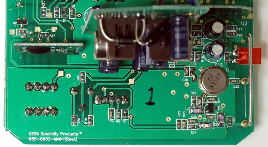
Click to zoom
Application Details
- Equipment Class
- DSC - Part 15 Security/Remote Control Transmitter
- Date of Grant
- Nov 06, 2006
- Application Purpose
- Original Equipment
- Date of Application
- Nov 06, 2006
- Equipment Note
- Wireless PIR Motion Sensor
- Frequency Range
- 315.00000000 - 315.00000000
- Company
- HeathCo LLC
- Country
- United States
Documents & Files
Document Text
Text extracted from the exhibit documents filed with the FCC. Open a document above to read the original.
Users Manual
DRAFT COPY ON 1 2 3 4 ON 1 2 3 4 ON 1 2 3 4 ENGLISH Remote Controlled Products This manual includes operating instructions for a variety of remote controlled products. All products work on the same principle and use the same code setting information. Please read all instructional information and note any specific information pertaining to your particular product. FEATURES • Products are UL/cUL and/or FCC/IC tested and approved. • Operational range of up to 100 feet. Heath ® /Zenith wireless lighting controls are designed to work together. Simply determine which transmitter(s) you would like to have control which receiver(s) and set the code setting to match. CODE SETTINGS Note: Most single system installations will not require any change to the code setting. Transmitter(s) and receiver(s) must have the same code and group setting to work together. Switches 1 through 3 set the code. Switch 4 sets the Group (A or B). See page 2 for switch locations. Transmitter(s)/ Receiver(s) Code Group “B” Example 1 - Code Settings, System 1 (Factory Setting) Transmitter(s)/ Receiver(s) Code Group “A” ( – Indicates Position of Switch) Example 2 - Code Settings, System 2 Note: When operating more than one system independently of each other, set each system to a different code. There are 8 codes avail- able by changing the settings of switches 1 through 3. Transmitter(s)/ Receiver(s) Code Group “A” © 2006 DESA Specialty Products™ 598-11271-00 CODE SWITCH LOCATIONS Solar Powered Motion Sensor Code Switches ON DUALBRITE ® ON-TIME Off 3Hr Dusk to TEST 1 5 Dawn (Mins) CODE RANGE DETECT 1 2 3 4 MIN MAX NIGHT DAY ONLY NIGHT ON 1 2 3 4 Close-Up of Typical Code Switch (Factory Default Setting is Off) Note: The “X” has been placed on the switches to help clarify the code settings on the previous page. 2598-1271-00 DRAFT COPY SOLAR POWERED MOTION SENSOR Features: • No wiring required. • Up to 80 feet sensing range, 360° Cover- age. • Adjustable sensitivity. • Day/Night or Night only operation. • Optional half power accent lighting • Test mode. • Uses 2 AAA NiMH rechargeble batteries (included). • Controls receivers up to 100 feet away. Solar Powered Motion Sensor L o c k U n l o c k Installing Batteries 1. Remove battery compartment cover by rotating clear solar panel cover counterclockwise. 2. Install 2 AAA NiMH rechargeble batteries (included) according to polarity markings inside the battery compartment. 3. Replace battery compartment cover by reversing the above instructions. L o c k U n l o c k L o c k U n l o c k Removing Solar Panel Cover / Battery Compartment - Top View Clear Solar Panel Cover Rotation Indicators Solar Panel Cover / Battery Compartment - Bottom View 3598-1271-00 ENGLISH DRAFT COPY Continued DUALBRITE ® Dimmer Control Light comes on half power for selected time after dusk (Off, 3 hr., until dawn). If motion is sensed, the light turns on full power for the ON-TIME (1 or 5 minutes) then returns to accent mode. 1. Select amount of time for accent lighting (DUALBRITE ® con- trol). 2. Select the amount of time light stays on full bright after motion is detected (On-Time control). Night Only or 24 Hour Mode This sensor is able to detect motion day and night or night only. Slide the DETECT switch to either the DAY/NIGHT or NIGHT ONLY position. Range Control Adjust the RANGE to increase or decrease the range as needed. Too much sensitivity may cause false triggering due to heat sources in the coverage area. The sensor on this light fixture detects “motion” by the movement of heat (body heat) across the coverage area. However, following are examples of objects that also produce heat and can cause the sensor to false trigger: • Pools of Water • Air Conditioners • Dryer Vents • Fenced-In Animals • Heating Vents • Automobile Traffic If you suspect that a heat source of this type is falsely triggering the sensor, adjust the RANGE control as needed to avoid false triggering. L o c k U n l o c k SETTING CONTROLS The controls are located on the bottom of the sensor unit. To remove the base, carefully grasp the sensor unit and the base and pull apart. IMPORTANT: Be careful not to press against the sensor lenses when grasping the sensor unit. ON DUALBRITE ® ON-TIME Off 3Hr Dusk to TEST 1 5 Dawn (Mins) CODE RANGE DETECT 1 2 3 4 MIN MAX NIGHT DAY ONLY NIGHT ON DUALBRITE ® ON-TIME Off 3Hr Dusk to TEST 1 5 Dawn (Mins) CODE RANGE DETECT 1 2 3 4 MIN MAX NIGHT DAY ONLY NIGHT ON DUALBRITE ® ON-TIME Off 3Hr Dusk to TEST 1 5 Dawn (Mins) CODE RANGE DETECT 1 2 3 4 MIN MAX NIGHT DAY ONLY NIGHT ON D UAL B RITE ® ON-TIME Off 3Hr Dusk to TEST 1 5 Dawn (Mins) CODE RANGE DETECT 1 2 3 4 MIN MAX NIGHT DAY ONLY NIGHT ON D UAL B RITE ® ON-TIME Off 3Hr Dusk to TEST 1 5 Dawn (Mins) CODE RANGE DETECT 1 2 3 4 MIN MAX NIGHT DAY ONLY NIGHT Detect Control D UALBRITE ® ControlON-TIME Control Range Control Sensor Lense Base Sensor Unit Removing Base from Sensor Unit Setting Controls - Bottom View of Sensor Unit Solar Panel Cover / Battery Compartment LED Indicator 4598-1271-00 DRAFT COPY Installing Solar Motion Sensor 1. Attach the sensor unit to the ground spike. Note: If you need to raise the sensor unit an additional 6”, use the extension rod. 2. Determine where you want to install the motion sensor. IMPORTANT: Place sensor where it will be able to receive 4 to 6 hours of direct sunlight each day. 3. Aim the sensors in the direction of desired coverage. Note: The sensors have a greater range directly in front of them than they do to the sides. 4. While holding the ground spike in the direction determined, remove the sensor unit (and extension rod if attached). 5. Place the ground spike on the ground and press into the soil. If necessary, use a rubber mallet to drive the ground spike into the ground. 6. Reattach the sensor unit (and extension rod, if applicable) to the ground spike. Check Operation and Adjustment Note: When first turned on or when switching modes wait 30 seconds. Note: When using test mode to check operation in the day ti…
Text truncated - open the document above for the full version.
Block Diagram
DESA Specialty Products Confidential 8/ 12/200 6 DESA Specialty Products Wireless Wall Switch Transmitter Model #: 60 3 3-TX Description: 315 MHz Wireless Wall Switch TransmitterFCC ID (proposed): BJ4-WRC 60 3 3TX Transmitter Circuit Block Diagram Power Supply Custom ASIC 12-bit (5-Volt DC from data Encoder IC RF Oscillator 2.4V DC Source) from motion sensor (3 KHz Data Rate) ( 315 MHz) & 4-Position Dipswitch File: 6023-TX Block Diagram
ID Label/Location Info
ON D UAL B RITE ® ON-TIME Off 3Hr Dusk to TEST 1 5 Dawn (Mins) CODE RANGE DETECT 1 2 3 4 MIN MAX NIGHT DAY ONLY NIGHT FCC ID: BJ4-WRC6033TX IC: 3984A-6033TX This device complies with part 15 of the FCC Rules. Operation is subject to the following conditions: (1) this device may not cause harmful interference, and (2) this device must accept any interference received, including interference that may cause undesired operation. DESA Specialty Products™, Bowling Green, KY 6033-TX Made in China 390-6033XX-TX1A
ID Label/Location Info
Label Location Clarification Question : Label location looks like it is under a cover. This is not permitted please clarify how the label is visible to the end user. Applicant Answer : The label is located in an area that the customer must access in order to use the devise; which would be in a “conspicuous area” according to the FCC requirements. The device is packaged in 2 separate parts, the (Sensor module) and the (Stake), the location if the label is on the same surface as the code, day-night, time on, dusk to dawn and sensitivity selection switches. The consumer must set these switches prior to usage and then assemble the unit. This is detailed in the manual. This unit is a transmitter only, and the transmitter must be set to the same code as the (sold separately) receiver. The unit will not operate correctly prior to the above steps.
Operational Description
DESA Specialty, LLC 8/14/2006 Confidential 6033-TX Wireless Solar PIR Transmitter Wireless Solar PIR Transmitter Model Number: 6033-TX General Description: The 6033-TX Wireless Solar PIR Transmitter is a transmitting device used for the remote control of lighting by utilizing RF transmission technology and a compatible RF receiver. The device is capable of transmitting several commands, which that are used by the compatible receiver to turn the room lights ON, OFF or to dim the lights to a prescribed level. The housing is made of a durable plastic and houses the electronics, batteries and solar cell used for recharging. . The assembly is designed to mount to a stake with and optional extension to allow the sensor to be positioned at 2 different heights. The electrical circuitry is comprised of a set of AAA rechargeable batteries, a solar panel for recharging, a 2.4 to 5-Volt DC power supply converter, 3 tact switches, one 4-position dipswitch, a custom motion sensing ASIC, a digital encoder for the RF data stream, a 315 MHz RF oscillator circuit, and complementary passive components. All circuitry is mounted on two separate PCBs. The printed circuit boards are double-sided and have a 94V-0 rating. Specifications: • Input: 2.4VDC by battery or solar panel • Circuit voltage: ~5.0 volts DC. • RF Carrier Frequency: 315 MHz • Modulated Data Frequency: 3.0 KHz • User-selectable address codes: 16 Theory of Operation: The wireless transmitter is normally off with the RF transmission starting when one of the two PIR sensors detects motion. At this time, the encoder outputs a 3 KHz, 1 sync bit plus 12-data bit transmission to the RF oscillator circuit transmitting the information at a carrier frequency of 315 MHz. The encoder transmits for approximately 1 second. It is then reset for another motion event. The 12-bit output consists of a sync bit, 8-bit address and 4 bits of data. The user- selectable address is set with a four-position dipswitch. The other 4 address lines are permanently set. The receiving unit to be controlled is set to the same address as the wireless transmitter.
Parts List/Tune Up Info
-- P-CADBill of MaterialsWireless Solar PIR(08-14-06).SCH ====================================================================== CountRefDesValuePublished -------------------- ----------------------------- 1D31N4148 1D11N5817 1JP1 1U4HT7022A 2AAA11.2V AAA2 1SP1Solar Panel 2C251nF C29 1C261pF 1C277pF 1C221.5pF 1C234pF 1C3012pF 1C24100nF 1C28100pF 1C50.1uF 1C30.1uF 1C153.3nF 2C10100nF C16 2C810nF C18 1C1322uF 1C1922uF, NP 1C11100nF 1C6470pF5% 1C141000pF 5C447uF C7 C9 C12 C17 1C1100uF 1C2220uF 1CDS1{Value} 1D2BAT54 1U3HT-12E 1L1100uH 1LED1RED 1Q3{Value}NPN 1Q22N3904 1L690mmWire 2U1{Value} U5 1U2 1R161M 2R3522 R34 1R3356K 1R1122K 1R147K 2R2470K R3 4R61M R23 R28 R37 1R271.1M1% 1R172K 2R123.3M R20 1R104.7K 1R1827K 5R447K R21 R25 R26 R36 1R2468K 5R9100K R22 R29 R30 R31 1R19120K 1R14180K 1R7270K 1R32470K 2R8560K R15 1R13680K 1R5845K1% 1X2315Mhz 1L31uH 2L447nH L5 1SW324HR/NIGHT 2SW1{Value} SW2
Test Report
FCC Part 15 Subpart C, 15.231 : June 2006 Test Report: 6W72013 issue 2 Applicant: DESA Speciality LLC PO Box 90004, 2901 Industrial Ave, Bowling Green, KY 42102, USA Apparatus: 6033-TX FCC ID: BJ4-WRC6033TX In Accordance With: FCC Part 15 Subpart C, §15.231 Periodic operation in the band 40.66-40.70MHz and above 70 MHz. Tested By: Nemko Canada Inc. 303 River Road Ottawa, Ontario K1V 1H2 Authorized By: Xu Jin, Wireless Specialist Date: Total Number of Pages: 21 Nemko Canada Inc. REPORT SUMMARY Report Number: 6W72013 FCC ID: BJ4-WRC6033TX Specification: FCC Part 15 Subpart C, 15.231 Page 2 of 21 Report Summary These tests were conducted on a sample of the equipment for the purpose of demonstrating compliance with Part 15, Subpart C. Radiated tests were conducted in accordance with ANSI C63.4-2003. Radiated emissions are made on an open area test site. A description of the test facility is on file with the FCC. The assessment summary is as follows: Apparatus Assessed: 6033-TX Specification: FCC Part 15 Subpart C, 15.231 Compliance Status: Complies Exclusions: None Non-compliances: None Report Release History: Original Release Author: Roman Kuleba, EMC/Wireless Specialist Note that the results contained in this report relate only to the items tested and were obtained in the period between the date of initial receipt of samples and the date of issue of the report. This test report has been completed in accordance with the requirements of ISO/IEC 17025. Nemko Canada Inc. authorizes the applicant to reproduce this report provided it is reproduced in its entirety and for use by the company’s employees only. Any use which a third party makes of this report, or any reliance on or decisions to be made based on it, are the responsibility of such third parties. Nemko Canada Inc. accepts no responsibility for damages, if any, suffered by any third party as a result of decisions made or actions based on this report. Nemko Canada Inc. REPORT SUMMARY Report Number: 6W72013 FCC ID: BJ4-WRC6033TX Specification: FCC Part 15 Subpart C, 15.231 Page 3 of 21 TABLE OF CONTENTS Report Summary......................................................................................................................................... 2 Section 1 : Equipment Under Test............................................................................................................. 4 1.1 Product Identification .................................................................................................................................4 1.2 Samples Submitted for Assessment............................................................................................................4 1.3 Theory of Operation ...................................................................................................................................4 1.4 Technical Specifications of the EUT ..........................................................................................................5 1.5 Block Diagram of the EUT.........................................................................................................................5 Section 2 : Test Conditions......................................................................................................................... 6 2.1 Specifications .............................................................................................................................................6 2.2 Deviations From Laboratory Test Procedures ............................................................................................6 2.3 Test Environment .......................................................................................................................................6 2.4 Test Equipment...........................................................................................................................................6 Section 3 : Observations ............................................................................................................................. 7 3.1 Modifications Performed During Assessment ............................................................................................7 3.2 Record Of Technical Judgements ...............................................................................................................7 3.3 EUT Parameters Affecting Compliance .....................................................................................................7 3.4 Test Deleted................................................................................................................................................7 3.5 Additional Observations .............................................................................................................................7 Section 4 : Results Summary ..................................................................................................................... 8 4.1 FCC Part 15 Subpart C : Test Results ........................................................................................................9 Appendix A : Test Results ........................................................................................................................ 10 Clause 15.209(a) Radiated Emissions within Restricted Bands ..........................................................................10 Clause 15.231(a)(2) Automatically Activated Transmitter..................................................................................15 Clause 15.231(b) Radiated Emissions (not in restricted bands) ..........................................................................17 Clause 15.231(c) 20dB Bandwidth ......................................................................................................................19 Appendix B : Setup Photographs ............................................................................................................ 20 Appendix C : Block Diagr…
Text truncated - open the document above for the full version.
Contact Information
Applicant
Jeff Bessinger(Associate Regulatory Engineer)
Technical Contact
Non-Technical Contact
Nemko Canada Inc.Bill Waterhouse
[email protected]613 737 9680
Test Firm
Nemko Canada Inc. (Ottawa)Charles Neal
Technical Specifications
| # | Rule Parts | Frequency Range | Power Output |
|---|---|---|---|
| 1 | 15.231 | 315 MHz - 315 MHz | - |
Other Applications from HeathCo LLC

BJ4-9309
Apr 01, 2020Connected LED video security motion light
Equipment Class
DTS - Digital Transmission System
BJ4-9000
Mar 25, 2020Connected Wired Decorative Motion Light
Equipment Class
DTS - Digital Transmission System
BJ4-WLTRX9600
Jan 05, 2020Video Doorbell with 2.4GHz wifi
Equipment Class
DTS - Digital Transmission System
BJ4-WLTX204
Jul 19, 2015Wireless Doorbell extender Kit
Equipment Class
DSC - Part 15 Security/Remote Control Transmitter
BJ4-WLTX208
Jul 06, 2015Wireless Door Chime Transmitter
Equipment Class
DSC - Part 15 Security/Remote Control Transmitter