BJM-KA1PC USB Headset
Tatung Company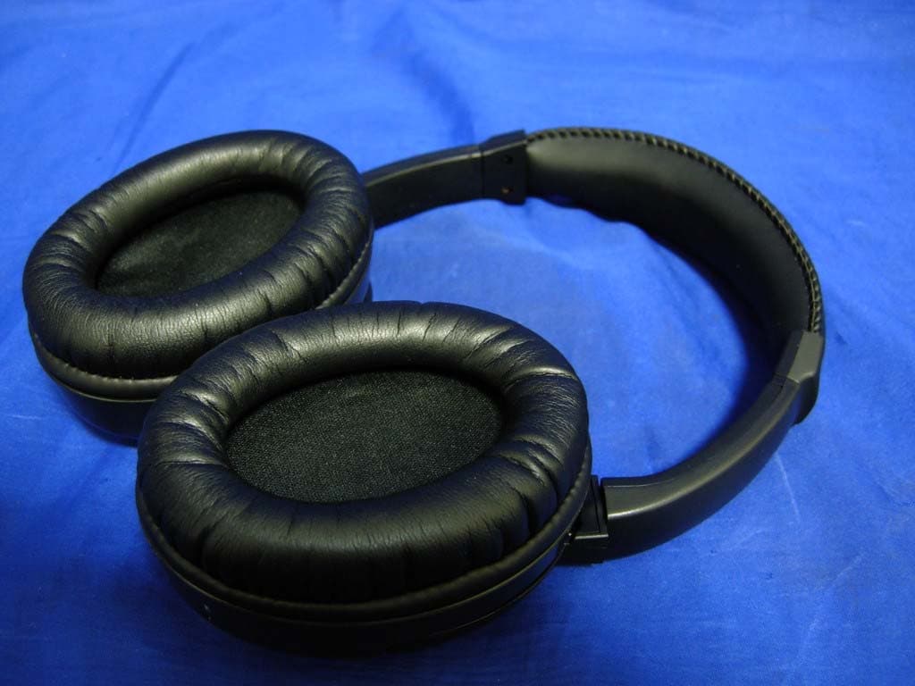
Click to zoom
Application Details
- Equipment Class
- DTS - Digital Transmission System
- Date of Grant
- May 21, 2007
- Application Purpose
- Original Equipment
- Date of Application
- May 14, 2007
- Equipment Note
- PC USB Headset
- Frequency Range
- 2405.00000000 - 2479.00000000
- Company
- Tatung Company
- Country
- Taiwan
Documents & Files
Document Text
Text extracted from the exhibit documents filed with the FCC. Open a document above to read the original.
Users Manual
Certification and Safety Approvals Unique Features Specification Product Accessories Parts Introduction Length adjustment LED IndicatorPairPower On/OffMicrophoneMini USB PortMicrophone On/OffReset 12345678 9 90 0 90 0 PC USB PUCK *1pc Warranty Card *1pc User Guide *1pc USB ChargingCable *1pc User Guide Symbols 1 23 4 5 Warranty Card Scope of WarrantySoundJet warrants that products of its own manufacture purchased from any SoundJet authorized distributor will meet the applicable SoundJet product specifications and be free from all defects in material and workmanship for the following periods from the date of purchase: Headset One(1) YearOther Accessories (other than headset) One(1) YearSoundJet's obligation under this warranty is limited to, at SoundJet's option, either:(a) repairing; or (b) replacing the product and accessories on an exchange basis. The warranty for such repaired or replaced the product and accessories will be valid for the remaining warranty period applicable for the original product and accessories.How To Get Warranty ServiceReturn the product and accessories to the outlet from which the product and accessories were purchased. All warranty claims must be presented within the applicable warranty periods above and accompanied by a valid proof-of-purchase.Warranty Exclusions and limitationsThis warranty shall not apply to: defects or damage resulting from use of the product and accessories in other than their normal and customary manner, eg, in excess of their maximum specifications or operating instructions;defects or damage form misuse, accident, neglect, improper testing, installation, alteration or modification of any kind, or spillage of food or liquid.installation, maintenance or repair performed by service personnel not authorized by SoundJet;products and accessories which have had the serial/identification numbers removed or made illegible;all plastic surfaces and all other externally exposed parts that are scratched or damaged due to customer normal use;operation or damage caused by ancillary or peripheral equipment not manufactured by SoundJet but used in conjunction with or accompanying the product and accessories.any other defects or faults which occur for reasons beyond the reasonable control of SoundJet. 7 KA-1 1 2 3 4 5 6 7 8 9 KA-1 P/N:E728924003 6 Steady red lightSteady greed lightFlashing green light Devices are waiting for pairingDevices are pairedDevices are not paired The headset is charging P C FCC StatementThis device complies with part 15 of the FCC rules. Operation is subject to the following two conditions: (1)This device may not cause harmful interference, and (2)This device must accept any interference received, including interference that may cause undesired operation. CEThis product is CE marked according to the provisions of the R&TTE Directive. (99/5/EC) KA-1 is the world first digital wireless headset that uniquely delivers the 2.1-channel audio performance with extra sound clarity and soft, deep bass effects. It provides a voice back channel that allows you to talk in conjunction with any kinds of PC voice applications. Examples of such applications include Skype, MSN, on-line gaming, and more. With the high performance audio and the unique feature set, KA-1 brings you a great value. To start, we like to introduce to you the important certification and safety approvals on this headset. Unique 2.1-Channel design - Each ear cup contains 2 speakers for extra clarity and deep bass performance.USB Plug-and-Play wireless headset that supports PC music/game sounds and back-channel voice simultaneously, no need to switch back and forth.USB Puck direct plug-in to the PC for instant use of VoIP, on-line game, DVD, and all kinds of entertainment running Windows 2000/XP, Macintosh OS10.4 and Linux Fedora 4, 5, and 6 operating systems.Ease of use, no software installation needed.Long standing use, over 15 hours of continuous listening time per charge.Easy charging through USB ports.Microphone switch on/off control.Built-in noise canceling microphone for superior voice quality.100 feet distance of effective use.Equipped with SafeBass safe resonance technology. PC USB WirelessHeadset *1pc KA-1 Wireless TechnologyListen Time (per charge)Talk Time (per charge)Standby TimeCharge Time (full charge)Distance of UseHeadset WeightUSB Puck WeightCharging MethodBattery TypeFrequency ResponseAudio QualityDistortion (T.H.D.) Speaker Drivers WiStereo TM for advanced 2-way digital transmission in the 2.4 GHz frequency bandApproximately 15 hoursApproximately 12 hoursApproximately 3 monthsApproximately 3 hours100 feet7.9 ounces1.8 ouncesThrough PC USB portLithium Polymer20Hz~30,000Hz (perfect for all music, game, and voice)Uncompressed audio for music (CD-quality) and voice (extra clarity)<0.08% (professional grade audio performance)2 on each side for full-range audio and sub-woofer enhancement with SafeBass technology30mm Neodymium for left/right channels40mm Neodymium for subwoofer Model R R ResetPress to reset the headset, in case this headset is not functioning properly. Microphone On/OffSwitch the button to control microphone on/off. Power On/OffPress this button to control power on/off.MicrophoneReceives voice input when the microphone is switched on.Mini USB PortConnect USB charging cable to PC for recharging.LED IndicatorA red indicator represents power functions.A green indicator represents signal connections.Press to increase the headset volume.Press to decrease the headset volume. 12345 67 89 PairPress pair button to connect the wireless headset and the USB Puck. P C PC USB Headset Handling the headset Do not bend, drop, crush, puncture, incinerate, or open the headset.Repairing the headsetNever attempt to repair the headset yourself. The headset does not contain any user serviceable parts. For service information, choose the headset help from the warranty card. The rechargeable battery in the headset should be replaced only by authorized service providers. …
Text truncated - open the document above for the full version.
Cover Letter(s)
Dear Tim, Concerning the comments of this applicaiton in the former letter, we revised the documents. pls help to check. 1) Users manual contains 20 cm statements. This appears not appropriate given the use of the device. Please remove statements relative to distance, but keep the non-colocation statements in the manual. Please review & correct..----We've revised the Users manual, pls see the attachment 2) Thank you for the many photographs to show the > 2.5 cm distance to the radiating element. Unfortunately it took about 10 minutes to piece together the photos and ensure myself it was > 2.5 cm. Kindly add line/information/marking on the device when shown on the head phantom to clearly denote where the antenna is located when showing the external photograph with the ruler.?--pls see the attachment "Antanna Photo-v960515" 3) IC requires RX emissions to be tested/shown as well. It does not appear this information was provided. Please review.----pls see the attachment "(KA-1) TestRpt-RX Emission-v960515 " 4) IC RSS-102 has different exemption requirements than the FCC for SAR. Please note that according to RSS-102, SAR is required. Please review and complete RSS-102 attestation Appendix A which was previously left blank.---We'll sent you the SAR document ASAP. 5) FYI .Equipment codes for 15.2247 on the 731 form should be DTS or DSS depending on the device, not DXX..--We changed the code, pls see the attachment "731Form-" Thanks and best regards. Emil y
Cover Letter(s)
Hi Tim, For this case,beacause our customer doesn't want to perform SAR test and they would like to reduce the RE outpower to meet IC regulation. We have re-test and issue the test report again as upload one. Pls help to check. If there's any comments, pls let me know. Thanks Emily
Cover Letter(s)
American Telecommunications Certification Body Inc. 6731 Whittier Ave, McLean, VA 22101 May 14, 2007 RE: Tatung Co. FCC ID: BJM-KA1 After a review of the submitted information, I have a few comments on the above referenced Application. 1) Users manual contains 20 cm statements. This appears not appropriate given the use of the device. Please remove statements relative to distance, but keep the non-colocation statements in the manual. Please review & correct. 2) Thank you for the many photographs to show the > 2.5 cm distance to the radiating element. Unfortunately it took about 10 minutes to piece together the photos and ensure myself it was > 2.5 cm. Kindly add line/information/marking on the device when shown on the head phantom to clearly denote where the antenna is located when showing the external photograph with the ruler. 3) IC requires RX emissions to be tested/shown as well. It does not appear this information was provided. Please review. 4) IC RSS-102 has different exemption requirements than the FCC for SAR. Please note that according to RSS-102, SAR is required. Please review and complete RSS-102 attestation Appendix A which was previously left blank. 5) FYI....For future bandwidth tests for this type of signal, kindly use a much smaller span (i.e. 2 – 5 MHz). 6) FYI....Equipment codes for 15.247 on the 731 form should be DTS or DSS – depending on the device, not DXX. Timothy R. Johnson Examining Engineer mailto: [email protected] The items indicated above must be submitted before processing can continue on the above referenced application. Failure to provide the requested information may result in application termination. Correspondence should be considered part of the permanent submission and may be viewed from the Internet after a Grant of Equipment Authorization is issued. Please do not respond to this correspondence using the email reply button. In order for your response to be processed expeditiously, you must submit your documents through the AmericanTCB.com website. Also, please note that partial responses increase processing time and should not be submitted. Any questions about the content of this correspondence should be directed to the sender.
Cover Letter(s)
American Telecommunications Certification Body Inc. 6731 Whittier Ave, McLean, VA 22101 May 16, 2007 RE: Tatung Co. FCC ID: BJM-KA1 After a review of the submitted information, I have a few comments on the above referenced Application. 1) The newly provided photographs for the antenna distance seem to indicate that the antenna distance is only 2 cm. If this is the case, then SAR would be required for FCC. Alternatively, to avoid SAR, both the EIRP and conducted power would need to be reduced below 24 mW levels Timothy R. Johnson Examining Engineer mailto: [email protected] The items indicated above must be submitted before processing can continue on the above referenced application. Failure to provide the requested information may result in application termination. Correspondence should be considered part of the permanent submission and may be viewed from the Internet after a Grant of Equipment Authorization is issued. Please do not respond to this correspondence using the email reply button. In order for your response to be processed expeditiously, you must submit your documents through the AmericanTCB.com website. Also, please note that partial responses increase processing time and should not be submitted. Any questions about the content of this correspondence should be directed to the sender.
External Photos
Report No.: 071L110-RFUSP01V02 Page : 1 of 6 Version:1.0 Attachment 2 : EUT Detailed Photographs (1) EUT Photo (2) EUT Photo
ID Label/Location Info
22 Chung Shan N. Road, 3 rd sec., Taipei, 104, Taiwan Tel: +886-2-25984803 FCC ID.: BJM-KA1 22, Chungshan N. Rd., 3rd Sec. Taipei, Taiwan, 104, R.O.C. . Tel : +886-2-25984803 FCC ID Label The FCC ID will be placed on the equipment as shown in the photograph below.
Internal Photos
Report No.: 071L110-RFUSP01V02 Page : 2 of 6 Version:1.0 (3) EUT Photo (4) EUT Photo Report No.: 071L110-RFUSP01V02 Page : 3 of 6 Version:1.0 (5) EUT Photo (6) EUT Photo Report No.: 071L110-RFUSP01V02 Page : 4 of 6 Version:1.0 (7) EUT Photo (8) EUT Photo Report No.: 071L110-RFUSP01V02 Page : 5 of 6 Version:1.0 (9) EUT Photo (10) EUT Photo Report No.: 071L110-RFUSP01V02 Page : 6 of 6 Version:1.0 (11) EUT Photo
Operational Description
Report No. 071L110-RFUSP05V01 Page: 6 of 42 Version:1.0 1.2. Operational Description The EUT is a PC USB Headset with a built-in 2.4GHz transceiver. There are 38 channels in 2405 – 2479MHz. The channels are separated by 2MHz. The signals are modulated by π/4 DQPSK The antenna type is chip antenna. Test Mode Mode 1: Transmitter
Test Report
Report No. 071L110-RFUSP05V01 Page: 1 of 40 Version:1.0 Test Report Product Name PC USB Headset Model No. KA-1, Q-BASSS-U FCC ID BJM-KA1 Applicant TATUNG CO. Address 22, Chungshan N. Rd., 3rd Sec. Taipei, Taiwan, 104, R.O.C. Date of Receipt Jan. 23, 2007 Issued Date May 17, 2007 Report No. 071L110-RFUSP05V01 The test results relate only to the samples tested. The test report shall not be reproduced except in full without the written approval of QuieTek Corporation. This report must not be used to claim product endorsement by NVLAP any agency of the U.S. Government Report No. 071L110-RFUSP05V01 Page: 2 of 40 Version:1.0 Test Report Certification Issued Date: May 17, 2007 Report No.: 071L110-RFUSP05V01 Test results relate only to the samples tested. The test report shall not be reproduced except in full without the written approval of QuieTek Corporation. This report must not be used to claim product endorsement by NVLAP any agency of the U.S. Government Product Name PC USB Headset Applicant TATUNG CO. Address 22, Chungshan N. Rd., 3rd Sec. Taipei, Taiwan, 104, R.O.C. Manufacturer TATUNG CO. Model No. KA-1, Q-BASSS-U Rated Voltage AC 120V/60Hz Working Voltage 3.7V (Battery) Trade Name TATUNG, LTB Applicable Standard FCC CFR Title 47 Part 15 Subpart C: 2006 CISPR 22: 2005 ANSI C63.4: 2003 Test Result Complied Documented By : ( Engineering Adm. Specialist / Rita Huang ) Tested By : (Engineer / Tim Sung) Approved By : ( President / Gene Chang ) Accredited by NIST (NVLAP) NVLAP Lab Code: 200533-0 0914 Report No. 071L110-RFUSP05V01 Page: 3 of 40 Version:1.0 TABLE OF CONTENTS Description Page 1. GENERAL INFORMATION .....................................................................................................5 1.1. EUT Description............................................................................................................................5 1.2. Operational Description ................................................................................................................6 1.3. Tested System Datails....................................................................................................................7 1.4. Configuration of Test System ........................................................................................................7 1.5. EUT Exercise Software .................................................................................................................7 1.6. Test Facility ...................................................................................................................................8 2. Conducted Emission....................................................................................................................9 2.1. Test Equipment..............................................................................................................................9 2.2. Test Setup ......................................................................................................................................9 2.3. Limits ............................................................................................................................................9 2.4. Test Procedure .............................................................................................................................10 2.5. Uncertainty ..................................................................................................................................10 2.6. Test Result of Conducted Emission.............................................................................................11 3. Peak Power Output ...................................................................................................................13 3.1. Test Equipment............................................................................................................................13 3.2. Test Setup ....................................................................................................................................13 3.3. Limit ............................................................................................................................................13 3.4. Uncertainty ..................................................................................................................................13 3.5. Test Result of Peak Power Output...............................................................................................14 4. Radiated Emission .....................................................................................................................16 4.1. Test Equipment............................................................................................................................16 4.2. Test Setup ....................................................................................................................................17 4.3. Limits ..........................................................................................................................................18 4.4. Test Procedure .............................................................................................................................19 4.5. Uncertainty ..................................................................................................................................19 4.6. Test Result of Radiated Emission................................................................................................20 5. Band Edge ..................................................................................................................................24 5.1. Test Equipment............................................................................................................................24 5.2. Test Setup ....................................................................................................................................24 5.3. Limit .................…
Text truncated - open the document above for the full version.
Test Setup Photos
Report No.: 071L110-RFUSP05V01 Page : 1 of 3 Version:1.0 Attachment 1: EUT Test Setup Photographs Front View of Conducted Test Back View of Conducted Test Report No.: 071L110-RFUSP05V01 Page : 2 of 3 Version:1.0 Front View of Radiated Test Back View of Radiated Test Report No.: 071L110-RFUSP05V01 Page : 3 of 3 Version:1.0 Front View of Radiated Test (Horn) Back View of Radiated Test (Horn)
Contact Information
Applicant
Chung Chang(Director)
Technical Contact
QuieTek CorporationNatasha Tai
[email protected]886-2-8792-6808
2F, No. 345, Xinhu 2nd Rd. · Taipei · Taiwan
Test Firm
QuieTek CorporationKevin (Yu-Lung) Chen
Technical Specifications
| # | Rule Parts | Frequency Range | Power Output |
|---|---|---|---|
| 1 | 15C | 2.40 GHz - 2.48 GHz | 4.90 mW |
Other Applications from Tatung Company

BJM-TH1WD
Oct 05, 2021TUF GAMING H1 WIRELESS DONGLE
Equipment Class
DXX - Part 15 Low Power Communication Device Transmitter
BJM-RSGB
Mar 22, 2021Gaming headset
Equipment Class
DTS - Digital Transmission System
BJM-TUFH3WLD
Jan 03, 2021TUF Gaming H3 Wireless dongle
Equipment Class
DXX - Part 15 Low Power Communication Device Transmitter
BJM-TUFH3WL
Dec 23, 2020TUF GAMING H3 WIRELESS
Equipment Class
DXX - Part 15 Low Power Communication Device Transmitter
BJM-TIH-F1500
May 26, 2015Induction Cooker
Equipment Class
8CC - Part 18 Consumer Device