BOI-UAXDVFMaxiva UAX Outdoor Transmitter
GatesAir, Inc.
Click to zoom
Application Details
- Equipment Class
- TNB - Licensed Non-Broadcast Station Transmitter
- Date of Grant
- Mar 03, 2010
- Application Purpose
- Original Equipment
- Date of Application
- Feb 28, 2010
- Equipment Note
- Maxiva UAX Outdoor Transmitter
- Frequency Range
- 716.00000000 - 722.00000000
- Company
- GatesAir, Inc.
- Country
- United States
Documents & Files
Document Text
Text extracted from the exhibit documents filed with the FCC. Open a document above to read the original.
Users Manual
Maxiva UAX Transmitter Outdoor Enclosure System 888-2711-001 Maxiva UAX Transmitter Outdoor Enclosure System User Manual Feb. 9, 2010 Rev: A T.M. No. 888-2711-001 © Copyright Harris Corporation 2010 All rights reserved ii888-2711-0012/9/10 WARNING: Disconnect primary power prior to servicing. 2/9/10888-2711-001iii WARNING: Disconnect primary power prior to servicing. Technical Assistance Technical and troubleshooting assistance for HARRIS Transmission products is available from HARRIS Field Service (factory location: Quincy, Illinois, USA) during normal business hours (8:00 AM - 5:00 PM Central Time). Telephone +1-217-222-8200 to contact the Field Service Department; FAX +1-217-221-7086; or E-mail questions to [email protected]. Emergency service is available 24 hours a day, seven days a week, by telephone only. On-line assistance, including technical manuals, white papers, software downloads, and service bulletins, is available at http://support.broadcast.harris.com/eservice_enu. Address written correspondence to Field Service Department, HARRIS Broadcast Communications Division, P.O. Box 4290, Quincy, Illinois 62305-4290, USA. For other global service contact information, please visit: http://www.broadcast.harris.com/contact. NOTE: For all service and parts correspondence, you will need to provide the Sales Order number, as well as the Serial Number for the transmitter or part in question. For future reference, record those numbers here: ___________________/____________________ Please provide these numbers for any written request, or have these numbers ready in the event you choose to call regarding any Service, or Parts requests. For warranty claims it will be required, and for out of warranty products, this will help us to best identify what specific hardware was shipped. Replaceable Parts Service Replacement parts are available from HARRIS Service Parts Department from 7:00 AM to 11:00 PM Central Time, seven days a week. Telephone +1-217-222-8200 or email [email protected] to contact the Service Parts Department. Emergency replacement parts are available by telephone only, 24 hours a day, seven days a week by calling +1-217-222-8200. Unpacking Carefully unpack the equipment and preform a visual inspection to determine if any apparent damage was incurred during shipment. Retain the shipping materials until it has been verified that all equipment has been received undamaged. Locate and retain all PACKING CHECK LISTs. Use the PACKING CHECK LIST to help locate and identify any components or assemblies which are removed for shipping and must be reinstalled. Also remove any shipping supports, straps, and packing materials prior to initial turn on. Returns And Exchanges No equipment can be returned unless written approval and a Return Authorization is received from HARRIS Broadcast Communications Division. Special shipping instructions and coding will be provided to assure proper handling. Complete details regarding circumstances and reasons for return are to be included in the request for return. Custom equipment or special order equipment is not returnable. In those instances where return or exchange of equipment is at the request of the customer, or convenience of the customer, a restocking fee will be charged. All returns will be sent freight prepaid and properly insured by the customer. When communicating with HARRIS Broadcast Communications Division, specify the HARRIS Order Number or Invoice Number. iv888-2711-0012/9/10 WARNING: Disconnect primary power prior to servicing. 2/9/10888-2711-001MRH-1 WARNING: Disconnect primary power prior to servicing. Manual Revision History Maxiva UAX Transmitter Outdoor Enclosure System Manual REV.DATEECNPages Affected / Description 2010 FEBCreate manual. MRH-2888-2711-0012/9/10 WARNING: Disconnect primary power prior to servicing. 2/9/10888-2711-001vii WARNING: Disconnect primary power prior to servicing. Guide to Using Harris Parts List Information The Harris Replaceable Parts List Index portrays a tree structure with the major items being leftmost in the index. The example below shows the Transmitter as the highest item in the tree structure. If you were to look at the bill of materials table for the Transmitter you would find the Control Cabinet, the PA Cabinet, and the Output Cabinet. In the Replaceable Parts List Index the Control Cabinet, PA Cabinet, and Output Cabinet show up one indentation level below the Transmitter and implies that they are used in the Transmitter. The Controller Board is indented one level below the Control Cabinet so it will show up in the bill of material for the Control Cabinet. The tree structure of this same index is shown to the right of the table and shows indentation level versus tree structure level. Example of Replaceable Parts List Index and equivalent tree structure: Replaceable Parts List Index Part Number Page Table 7-1. Transmitter 994 9283 001 7-2 Table 7-2. Control Cabinet 992 9244 002 7-3 Table 7-3. Controller Board 992 8344 002 7-6 Table 7-4. PA Cabinet 992 9400 002 7-7 Table 7-5. PA Amplifier 994 7894 002 7-9 Table 7-6. PA Amplifier Board 992 7904 002 7-10 Table 7-7. Output Cabinet 992 9450 001 7-12 The part number of the item is shown to the right of the description as is the page in the manual where the bill for that part number starts. Inside the actual tables, four main headings are used: •Table #-#. ITEM NAME - HARRIS PART NUMBER - this line gives the information that corresponds to the •Replaceable Parts List Index entry; •HARRIS P/N column gives the ten digit Harris part number (usually in ascending order); •DESCRIPTION column gives a 25 character or less description of the part number; •REF. SYMBOLS/EXPLANATIONS column 1) gives the reference designators for the item (i.e., C001, R102, etc.) that corresponds to the number found in the schematics (C001 in a bill of material is equiva - lent to C1 on the schematic) or 2) gives added information or further explanation (i.e., “Used for …
Text truncated - open the document above for the full version.
Cover Letter(s)
HARRIS CORPORATION Broadcast Communications Division 3200 Wismann Lane Post Office Box 4290 Quincy, IL USA 62305-4290 telephone 1-217-222-8200 www.harris.com February 16, 2010 Compliance Certification Services 47174 Benicia Street Fremont, CA 94538 Attn: Mr. Mike Kuo Dear Mike, This letter and the accompanying test report and documents are in application for FCC Certification of a series of Digital Television transmitters to be operated under the requirements of FCC Part 27.53 (f). Three models of the UAX outside enclosure Mobile DVF series of transmitters are included in this application, with power output ratings from 1000 watts to 2000 watts, before the output filter. All models use the identical sub-assemblies, with the only significant difference between them being the number of output amplifier modules used to produce the required power. The Harris Maxiva Models UAX2000FLS Outdoor System, UAX2000FLD Outdoor System, and UAX1000FLS Outdoor System are transmitters with rated output powers of, 2000W, and 1000W respectively, for operation in the 716-722 MHz band as authorized under FCC 47CFR27. Operation is on a single channel with center frequency of 719 MHz with Emission Designator 6M00W7W The UAX outside enclosure Mobile DVF series of transmitters are an advanced modular design, using the same components and assemblies in a building-block approach to create transmitters with output power ratings from 1000 watts to 2000 watts at the cabinet output connection. The number of PA (Power Amplifier) modules used is governed by the power output of each model. 2 PA modules are used in the UAX-DVF1000 transmitter, 4 modules in the UAX-DVF2000, The 3 specific models are listed below. • UAX2000FLS Outdoor System -2Kw RF Power Level with Single Exciter • UAX2000FLD Outdoor System - 2Kw RF Power Level with Dual Exciters and Transmitter Control Unit • UAX1000FLS Outdoor System- 1Kw RF Power Level with Single Exciter. A single outdoor cabinet houses all models Photos in the test report give details of the various parts of the transmitter. These data are submitted in support of the application for FCC authorization of these four models of the UAX outside enclosure Mobile product, under the required Certification method. We respectfully request these products be certified. Yours sincerely, Carl B Williams Systems Engineer Harris Broadcast Communications (217) 221-7334
Cover Letter(s)
DVF series Transmitter FCC Certification Application HARRIS CORPORATION Broadcast Communications Division 3200 Wismann Lane Post Office Box 4290 Quincy, IL USA 62305-4290 telephone 1-217-222-8200 www.harris.com Request for Confidentiality Pursuant to 47CFR 0.459, we hereby request that the following Exhibits be withheld from public inspection. -Block Diagrams -Technical/Operation Description -Schematics -Tune-up Description These exhibits contain information of a proprietary nature to our company, and possibly to our customers also. Information which could be obtained from the cited Exhibits, which are commonly known as "Trade Secrets", includes printed circuit trace routing, component selection, RF circuit "broadbanding" techniques, mechanical construction layouts and modulation methods. The confidentiality of such information is carefully guarded within our company, and only shared when further disclosure is restricted by binding agreement. Additional proprietary information is contained within drawings, schematics and equipment configuration instructions, normally supplied to customers only after their purchase of the described equipment. Our customers, after having made such purchases, have no reason to share the documents with other parties and, in some cases, may be restricted from doing so by binding agreement. Additionally, those documents are normally supplied as hard copies as part of the equipment's documentation, and often in a size that is difficult to duplicate with standard office equipment. We are therefore concerned that in the event the above described information were to be made available in a public forum, particularly one as easy to access as the World Wide Web, our competitors, or those of our customers, could easily obtain and use it to compromise our ability, and that of our customers, to maintain our respective competitive positions in the marketplace worldwide. We therefore respectfully ask that you honor our request to maintain that confidentiality in regard to the selected documents. To support the requested confidentiality, we have placed the information requested to be kept confidential in Exhibits whose cover pages are marked “Confidential”. Sincerely, Carl B Williams Systems Engineer (217) 221-7334 (office) (217) 221-7088 (fax) [email protected]
External Photos
Photos - External FCCID : BOI-UAXDVF
ID Label/Location Info
FCCID Label UAX2000 Outdoor System 9950068111G 716-722 MHz 55 2.0 X 230Split 60 24.5 BOI-UAXDVF FCCID Label Location
Internal Photos
Photos – Internal FCCID : BOI-UAXDVF
RF Exposure Info
DVF series Transmitter FCC Certification Application HARRIS CORPORATION Broadcast Communications Division 3200 Wismann Lane Post Office Box 4290 Quincy, IL USA 62305-4290 telephone 1-217-222-8200 www.harris.com RF Exposure statement Harris FCCID: BOI-UAXDVF To: FCC The transmission line, antenna, and supporting structure are integrated at the installation. RF Exposure is evaluated according to 47CFR1.1307 during installation and site licensing. Sincerely, Carl B Williams Systems Engineer (217) 221-7334 (office) (217) 221-7088 (fax) [email protected]
Test Report
Page 1 of 35 HARRIS CORPORATION Broadcast Communications Division assuredcommunications™ Certification of Compliance UAX Outdoor System TV Transmitter for FCC Title 47 This document is compiled to provide the data and records supporting a Certification of Compliance with FCC Rules set forth in 47CFR Parts 2 and 27. Certification as described in Part 2, Subpart J applies to all subsequent identical units marketed. Use of the Certification method requires that the required records are filed accompanying FCC Form 731. The test record shall be retained as required by 2.938(c). The UAX Outdoor Enclosure System is a self contained UHF transmission system designed to be installed in outdoor environments without the need of a shelter. Power levels of the UAX Outdoor Systems are 500W, 1000W, and 2000W. All are for operation in the 716-722 MHz band as authorized under FCC 47CFR27. Operation is on a single channel with center frequency of 719 MHz with Emission Designator 6M00W7W. The modulation is a 6 MHz FLO (Forward Link Only) signal. This is a COFDM signal made up of 4000 carriers. The intention of these tests is to demonstrate, by tests conducted on a UAX2000, the compliance of this series of transmitters. Our basis for this is that the performance of each of the transmitters is entirely governed by the performance of the individual modules. Therefore, measurements of the UAX2000FLD provide a sound basis to project the performance which will be shown by other models. Manufacturer Harris Broadcast Communications Street Address 3200 Wismann Lane City, State, Zip Quincy, IL 62305 Product being certified UAX Outdoor System Transmitter Series Models UAX500FLS, UAX1000FLS, UAX2000FLS, and UAX2000FLD Outdoor System FCC Identifier BOI-UAXDVF Type of Emission 6M00W7W, Single Frequency Network Frequency Range One 6 MHz channel 716-722 MHz (Channel 55) Power Range Adjustable from zero to rated power: 500/1000/2000W Maximum Power 2000 watts ahead of the output filter Model Tested UAX2000FLD Outdoor System Assembly Number 9950068017G Serial Number Tested Test Location Harris Bldg 5, 2700 Ellington Road, Quincy, IL Persons responsible for testing are: 16 February, 2010 Steve Rossiter, Harris Corp. Date 16 February, 2010 Terry Hollenberg, Harris Corp. Date 16 February, 2010 Carl Williams, Harris Corp. Date Page 2 of 35 HARRIS CORPORATION Broadcast Communications Division assuredcommunications™ Table of Contents As an aid to locating needed information in this document, the following Table of Contents links each portion of the record with the appropriate Rule and locates it in this document by page number. 1. Rule 47CFR2.938 Retention of records. ................................................................................ 3 2. Rule 47CFR2.1033 Application for certification................................................................... 4 3. General Information.................................................................................................................. 7 4. Rule 47CFR 2.1046 Measurements required: RF power output............................................... 9 4.1. Test Methodology ..................................................................................................................... 9 4.2. Test Equipment Used................................................................................................................ 9 4.3. Power Output Test Results ..................................................................................................... 10 5. Rule 47CFR2.1047 Measurements required: Modulation characteristics........................ 11 5.1. Harris Response ...................................................................................................................... 11 6. Rule 47CFR2.1049 Measurements required: Occupied bandwidth........................................ 11 6.1. Test Methodology ................................................................................................................... 12 6.2. Occupied Bandwidth Test Setup............................................................................................. 12 6.3. Test Equipment Used.............................................................................................................. 12 6.4. Test Results............................................................................................................................. 12 7. Rule 47CFR2.1051 Measurements required: Spurious emissions at antenna terminals. ........ 13 7.1. Test Methodology ................................................................................................................... 13 7.2. Spurious Emissions Test Setup............................................................................................... 14 7.3. Test Equipment Used.............................................................................................................. 15 7.4. Spurious Test Results, Close-In.............................................................................................. 15 7.5. Spurious Test Results, Wideband ........................................................................................... 17 8. Rule 47CFR2.1053 Measurements required: Field strength of spurious radiation......... 20 8.1. Test Methodology ................................................................................................................... 21 8.2. Radiated Emissions Test Setup ............................................................................................... 22 8.3. Test Equipment Used.............................................................................................................. 22 8.4. Test Results............................................................................................................................. 22 9. Rule 47CFR2.1055 Measurements required: Frequency stability..................................... 24 9.1. Test Methodology ..........…
Text truncated - open the document above for the full version.
Test Setup Photos
Photos – Test Setup FCCID : BOI-UAXDVF Spurious Emissions at Antenna Termnals Field Strength of Spurious Emissions
Contact Information
Applicant
John R Harmon(Compliance Engineer)
Technical Specifications
| # | Rule Parts | Frequency Range | Power Output | Emission | Tolerance |
|---|---|---|---|---|---|
| 3 | 27 | 716 MHz - 722 MHz | 2000 W | 6M00W7D | 5.3 Hz |
Other Applications from GatesAir, Inc.
BOI-GXLP300
Dec 04, 2024LPFM Transmitter
Equipment Class
TBC - Licensed Broadcast Station Transmitter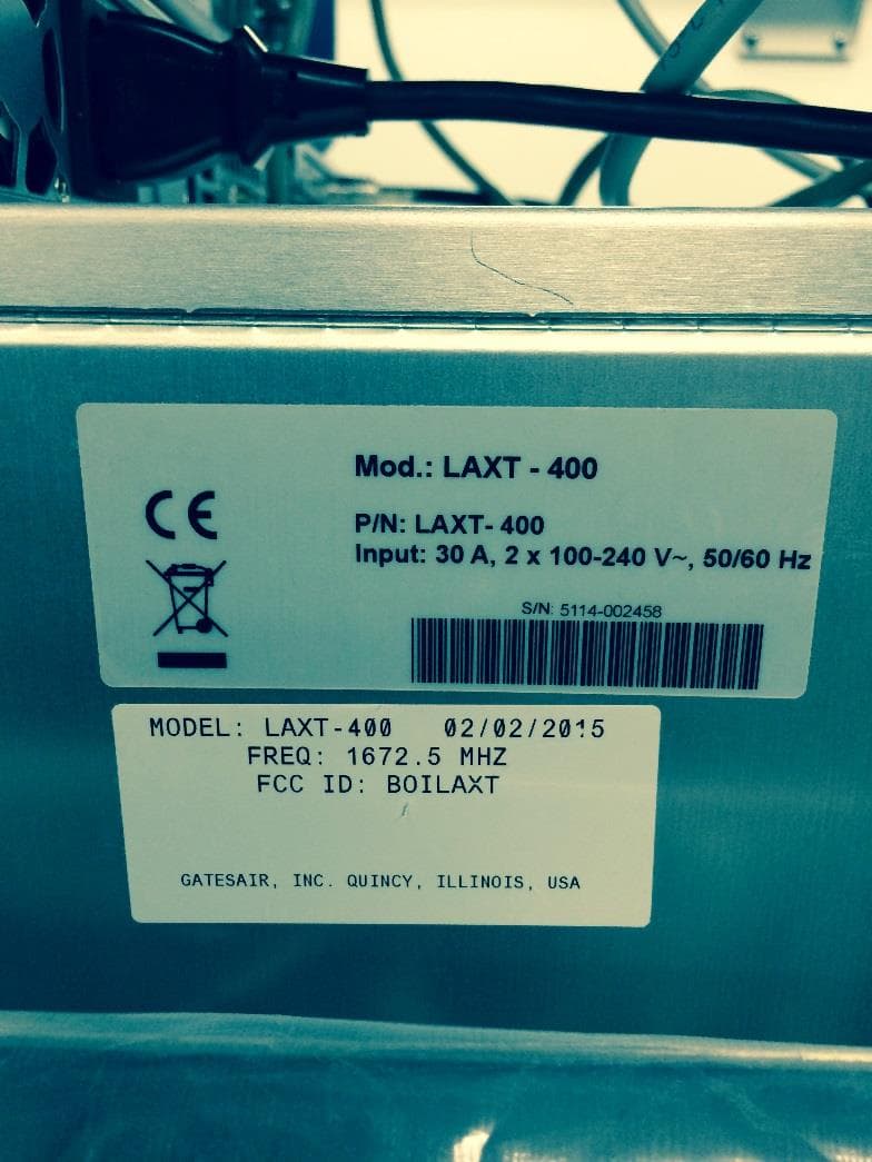
BOILAXT
Apr 23, 2015Maxiva LAXT Digital Television Transmitter
Equipment Class
TNB - Licensed Non-Broadcast Station Transmitter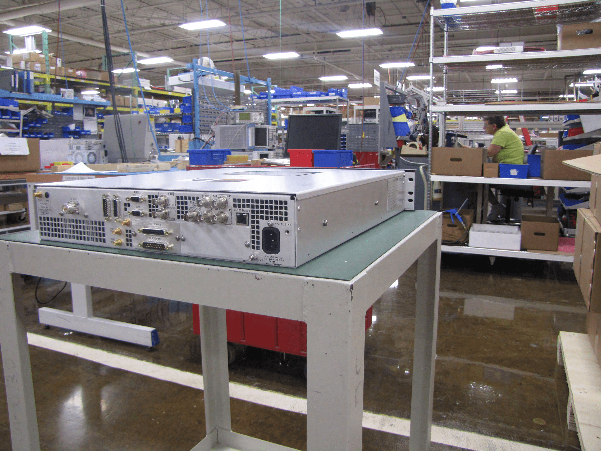
BOIUAXCC
Mar 24, 2014Maxiva Compact Class
Equipment Class
TBC - Licensed Broadcast Station Transmitter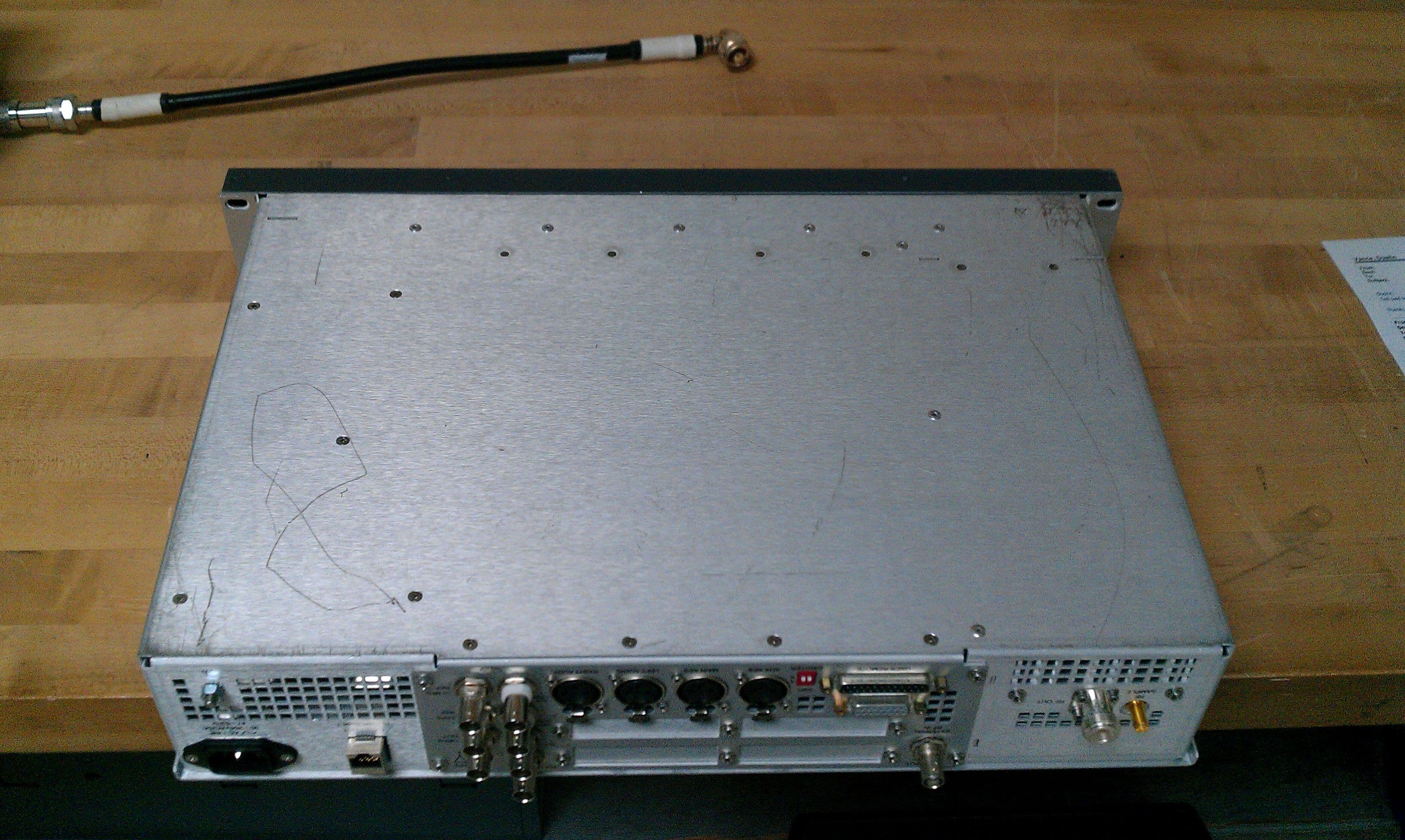
BOIFAXLP
Feb 04, 2014Flexiva Air-Cooled FM Transmitter/Exciter for Analog and Digital Standards Compact Class, Low Power - 50 W to 3.5 kW
Equipment Class
TBC - Licensed Broadcast Station Transmitter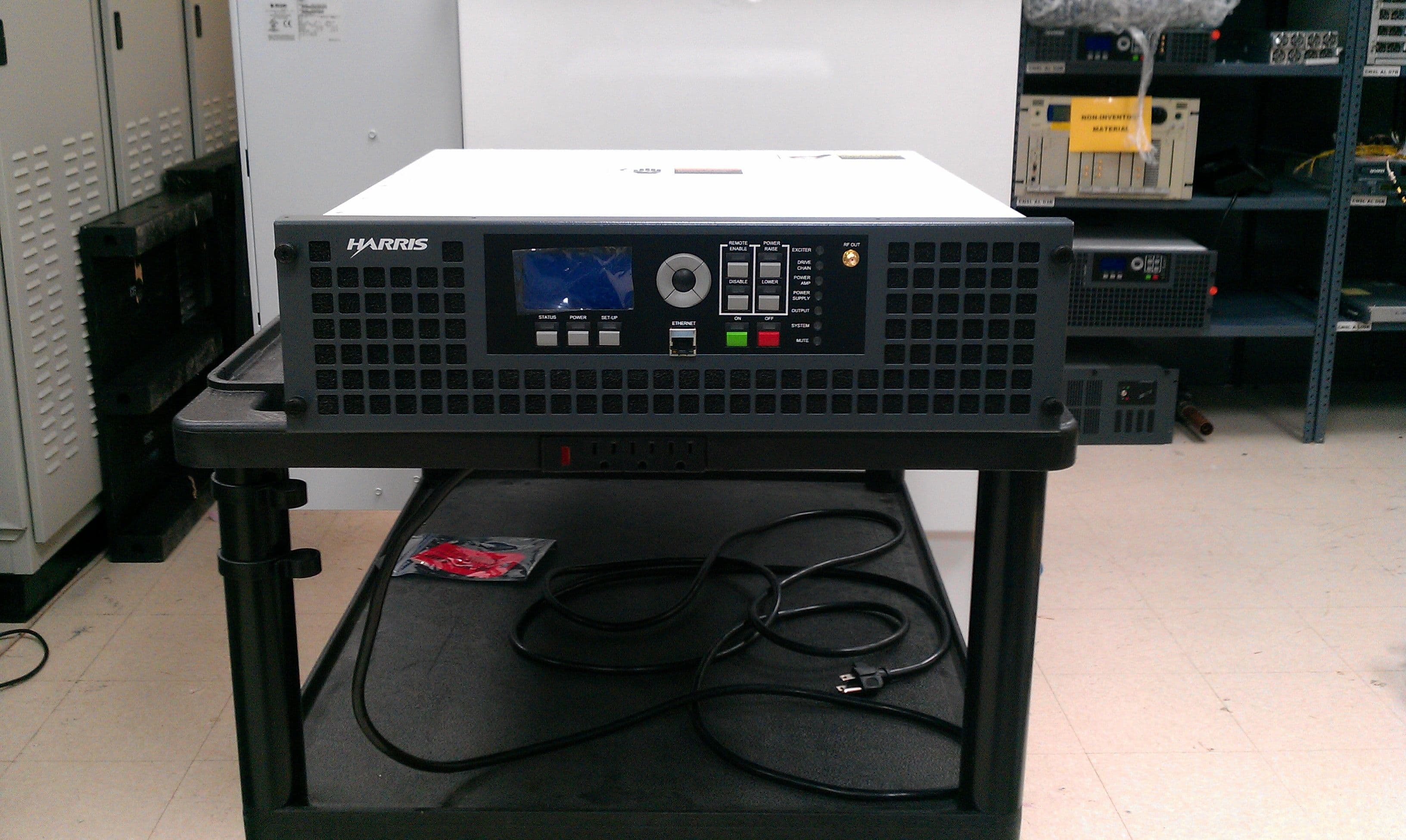
BOIFAXMP
Feb 03, 2014Air-Cooled FM Transmitter for Analog and Digital Standards Compact Class, Low Power
Equipment Class
TBC - Licensed Broadcast Station Transmitter