BOIDTV640-200DTV640/200T-E10 DVB-H Television Transmitter
GatesAir, Inc.
Click to zoom
Application Details
- Equipment Class
- TNB - Licensed Non-Broadcast Station Transmitter
- Date of Grant
- Jun 14, 2007
- Application Purpose
- Original Equipment
- Date of Application
- Jun 12, 2007
- Equipment Note
- DTV640/200T-E10 DVB-H Television Transmitter
- Frequency Range
- 698.00000000 - 704.00000000
- Company
- GatesAir, Inc.
- Country
- United States
Documents & Files
Document Text
Text extracted from the exhibit documents filed with the FCC. Open a document above to read the original.
Users Manual
DTV640-200 Transmitter FCC Certification Application HARRIS CORPORATION Broadcast Communications Division 3200 Wismann Lane Post Office Box 4290 Quincy, IL USA 62305-4290 telephone 1-217-222-8200 www.harris.com Installation and Operating Instructions Installation and operation of the DTV640-200 are fully described in user documentation C(a) - DTV 660 Operating Manual.
Cover Letter(s)
HARRIS CORPORATION Broadcast Communications Division 3200 Wismann Lane Post Office Box 4290 Quincy, IL USA 62305-4290 telephone 1-217-222-8200 www.harris.com June 6, 2007 Compliance Certification Services 47174 Benicia Street Fremont, CA 94538 Attn: Mr. Mike Kuo Dear Mike, This letter and the accompanying test report and documents are in application for FCC Certification of a series of Digital Television transmitters to be operated under the requirements of FCC Part 27.53 (f). The submission is for the Harris DTV640/200T-E10 digital television transmitter, for DVB-H service in the 698 to 704 MHz band. Transmitters in the intended service will provide a single-frequency network to allow reception of television by mobile devices. The DTV640/200T-E10 200 watt transmitter is a complete, rack mountable product, requiring only an input signal, GPS reference, and an external band pass limiting output filter to produce the COFDM signal for delivery to the antenna. A building-block approach to design will allow the creation of transmitters with other output powers. It is intended that other power levels will be submitted for certification at a later time. A front and rear photo on pages 9 and 10 of the test report, and additional photos in H - DTV640-200 Photos.pdf give details of the various parts of the transmitter. Respectfully yours, Karl Black Compliance Engineer Harris Broadcast Communications
Cover Letter(s)
DTV640-200 Transmitter FCC Certification Application HARRIS CORPORATION Broadcast Communications Division 3200 Wismann Lane Post Office Box 4290 Quincy, IL USA 62305-4290 telephone 1-217-222-8200 www.harris.com Application for Equipment Certification Table of Contents SUBMITTED TO: Compliance Certification Services 47174 Benicia Street Fremont, CA 94538 For: Harris Broadcast Communications DTV640-200 DVB-H Television Transmitter Table of Contents Exhibit Description Confidentiality Requested 1. Cover Letter NO 2. Table of Contents NO 3. Request for Confidentiality NO A. Equipment ID Label Plate and mounting location NO B. Modulation Description NO C. Technical Description of DTV640-200 Transmitter NO C(a) DTV660 Operating Manual YES C(b) Frequency Processing FAB66 YES D. Installation and Operating Instructions NO E. Tuning Up Procedure NO F. Schematics and Description of Circuits NO G. Output Bandpass Filter YES H Photos of DTV640-200 NO I. Test Report NO
Cover Letter(s)
DTV640-200 Transmitter FCC Certification Application HARRIS CORPORATION Broadcast Communications Division 3200 Wismann Lane Post Office Box 4290 Quincy, IL USA 62305-4290 telephone 1-217-222-8200 www.harris.com Request for Confidentiality Pursuant to 47CFR 0.459, we hereby request that the Exhibits marked on the Table of Contents "Confidentiality Requested", and also marked as "Confidential" on their cover pages, be withheld from public inspection. Each Exhibit so-marked contains information of a proprietary nature to our company, and possibly to our customers also. Information which could be obtained from the cited Exhibits, which are commonly known as "Trade Secrets", includes printed circuit trace routing, component selection, RF circuit "broadbanding" techniques, mechanical construction layouts and modulation methods. The confidentiality of such information is carefully guarded within our company, and only shared when further disclosure is restricted by binding agreement. Additional proprietary information is contained within drawings, schematics and equipment configuration instructions, normally supplied to customers only after their purchase of the described equipment. Our customers, after having made such purchases, have no reason to share the documents with other parties and, in some cases, may be restricted from doing so by binding agreement. Additionally, those documents are normally supplied as hard copies as part of the equipment's documentation, and often in a size that is difficult to duplicate with standard office equipment. We are therefore concerned that in the event the above described information were to be made available in a public forum, particularly one as easy to access as the World Wide Web, our competitors, or those of our customers, could easily obtain and use it to compromise our ability, and that of our customers, to maintain our respective competitive positions in the marketplace worldwide. We therefore respectfully ask that you honor our request to maintain that confidentiality in regard to the selected documents. To support the requested confidentiality, we have placed the information requested to be kept confidential in Exhibits whose cover pages and whose entries in the Table of Contents are marked as described above. Sincerely, Karl Black Compliance Engineer (217) 221-7543 (office) (217) 221-7088 (fax) [email protected]
Cover Letter(s)
http://mail.google.com/mail/?view=page&name=gp&ver=sh3fib53pgpk Harris Corporation - Broadcast Communication Division, FCC ID: BOIDTV640-200, Assessment NO.: AN07T6880, Notice#1 Inbox Reply from "[email protected]" <[email protected]> hide details Jun 12 (21 hours ago) to [email protected] cc [email protected] date Jun 12, 2007 4:49 PM subject Harris Corporation - Broadcast Communication Division, FCC ID: BOIDTV640-200, Assessment NO.: AN07T6880, Notice#1 Hello Karl, There were 3 relatively minor issues that need to be addressed from the review as shown below. Please email or call with any questions. Q1: The FCCID does not appear on the equipment label provided. Please provide a revised equipment label, or if the FCCID label is separate, provide the label that will bear the FCCID and show it's location on the equipment. Q2: The frequency stability measurements on page 40 of the test report were performed at a frequency of 686 MHz. The test frequency is outside the range of operation of this application. The measurement data is also more than 12 months old. Please confirm that the equipment described in the current filing is identical to equipment actually evaluated and that the measurements are in fact relevant to this filing. Q3: Pages 12 and 20 of the test report include a reference to 27.53(a)(4). 27.53(a) and all subparagraphs including (a)(4) are for operation in 2305-2320 MHz and 2345-2360 MHz bands and are not relevant to this 700 MHz filing. The out of band emissions requirements for this 700 MHz filing are contained in 27.53(f) exclusively. There does not appear to be any issue of non-compliance related to the references to 27.53(a)(4) but its inclusion is misleading. Please revise the report to remove the references to 27.53(a)(4). The items indicated above must be submitted before processing can continue on the above referenced application. Failure to provide the requested information within 30 days of the original e-mail date may result in application dismissal and forfeiture of the filing fee. Also, please note that partial responses increase processing time and should not be submitted. Any questions about the content of this correspondence should be directed to the e-mail address listed below the name of the sender. Best regards Tim Dwyer CCS Technical Reviewer Reply Reply to all Forward Invite [email protected] to Gmail Reply from "Black, Karl" <[email protected]> hide details 12:58 pm (1 hour ago) to [email protected] cc "Williams, Carl (cwilli05)" <[email protected]>, "Rosevold, Kim" <[email protected]> date Jun 13, 2007 12:58 PM subject RE: Harris Corporation - Broadcast Communication Division, FCC ID: BOIDTV640-200, Assessment NO.: AN07T6880, Notice#1 http://mail.google.com/mail/?view=page&name=gp&ver=sh3fib53pgpk (1 of 3)6/13/2007 2:31:37 PM http://mail.google.com/mail/?view=page&name=gp&ver=sh3fib53pgpk Dear Tim, I'll respond to each item below. I've uploaded revised sections A and I to the web site. I believe I've fully responded to each of these issues, but please let me know if there are other questions. As always, thanks very much for your quick response and very helpful comments. Best regards, Karl Black Compliance Engineer Harris Broadcast Communications (217) 221-7543 -----Original Message----- From: [email protected] [mailto:[email protected]] Sent: Tuesday, June 12, 2007 3:49 PM To: Black, Karl Cc: [email protected] Subject: Harris Corporation - Broadcast Communication Division, FCC ID: BOIDTV640-200, Assessment NO.: AN07T6880, Notice#1 Hello Karl, There were 3 relatively minor issues that need to be addressed from the review as shown below. Please email or call with any questions. Q1: The FCCID does not appear on the equipment label provided. Please provide a revised equipment label, or if the FCCID label is separate, provide the label that will bear the FCCID and show it's location on the equipment. That is somewhat embarrasing. I had thought to FCC ID we proposed was added to the standard label, but clearly it was not. I've revised the document and also the section in the test report where we refer to the ID label to show the label we will use. Q2: The frequency stability measurements on page 40 of the test report were performed at a frequency of 686 MHz. The test frequency is outside the range of operation of this application. The measurement data is also more than 12 months old. Please confirm that the equipment described in the current filing is identical to equipment actually evaluated and that the measurements are in fact relevant to this filing. The test was performed on a model of the exciter whose frequency control circuits are identical to those in the EUT. This transmitter includes a digital multi-mode exciter which is used for both digital and analogue service. The input circuits and some of the modulation processing circuits, and the software, change as is required by the type of signal to be transmitted, but the frequency control circuits do not. There has been no change to the frequency control circuits of the exciter since the referenced test was done, so this EUT is in fact identical to the one tested, as regards frequency control. http://mail.google.com/mail/?view=page&name=gp&ver=sh3fib53pgpk (2 of 3)6/13/2007 2:31:37 PM http://mail.google.com/mail/?view=page&name=gp&ver=sh3fib53pgpk I've amended the description on that section of the Test Report to make that more clear. Q3: Pages 12 and 20 of the test report include a reference to 27.53(a)(4). 27.53(a) and all subparagraphs including (a)(4) are for operation in 2305-2320 MHz and 2345-2360 MHz bands and are not relevant to this 700 MHz filing. The out of band emissions requirements for this 700 MHz filing are contained in 27.53(f) exclusively. There does not appear to be any issue of non-compliance related to the references to 27.53(a)(4) but its inclusion is misleading. Please revise the report to remove the references to 27.53(a)(4). I see that you are right…
Text truncated - open the document above for the full version.
External Photos
DTV640-200 Transmitter FCC Certification Application HARRIS CORPORATION Broadcast Communications Division 3200 Wismann Lane Post Office Box 4290 Quincy, IL USA 62305-4290 telephone 1-217-222-8200 www.harris.com DTV640-200 Photos.pdf Contents 1) Unit complete 2) Amplifier V641-100D 977-271-001 3) Central processing unit CPU 660 977-262-001 4) Power Supply SVG 660 977-035-001 5) Frequency Processing FAB 662 977-032-003 6) COFDM encoder OFE 977-474-001 7) IQ Entzerrer IQE 665 977-265-001 8) Up converter AU 616 977-315-001 9) Broadband amplifier BBV 607/1 977-438-001 Fotodocumentation DTV640/200T-E10 Contents 1) Unit complete 2) Amplifier V641-100D 977-271-001 3) Central processing unit CPU 660 977-262-001 4) Power Supply SVG 660 977-035-001 5) Frequency Processing FAB 662 977-032-003 6) COFDM encoder OFE 977-474-001 7) IQ Entzerrer IQE 665 977-265-001 8) Up converter AU 616 977-315-001 9) Broadband amplifier BBV 607/1 977-438-001 1) Unit complete Closed Open Front Top Rear 2) Amplifier V641-100D 977-271-001 Closed Open 3) Central processing unit CPU 660 977-262-001 Closed Opened 4) Power Supply SVG 660 977-035-001 Closed Opened 5) Frequency Processing FAB 662 977-032-003 Opened 6) COFDM encoder OFE 977-474-001 Opened 7) IQ Entzerrer IQE 665 977-265-001 Closed Opened 8) Up converter AU 616 977-315-001 Closed Opened 9) Broadband amplifier BBV 607/1 977-438-001 Closed Opened
ID Label/Location Info
DTV640-200 Transmitter FCC Certification Application HARRIS CORPORATION Broadcast Communications Division 3200 Wismann Lane Post Office Box 4290 Quincy, IL USA 62305-4290 telephone 1-217-222-8200 www.harris.com Equipment ID Label Plate and Mounting Location The Equipment ID Label is engraved on a metal plate along with product identification information. The plate is installed in a suitable location on each transmitter. I. Drawing of ID Label Plate 2. Location of ID plate on the DTV640-200 Transmitter
Internal Photos
DTV640-200 Transmitter FCC Certification Application HARRIS CORPORATION Broadcast Communications Division 3200 Wismann Lane Post Office Box 4290 Quincy, IL USA 62305-4290 telephone 1-217-222-8200 www.harris.com DTV640-200 Photos.pdf Contents 1) Unit complete 2) Amplifier V641-100D 977-271-001 3) Central processing unit CPU 660 977-262-001 4) Power Supply SVG 660 977-035-001 5) Frequency Processing FAB 662 977-032-003 6) COFDM encoder OFE 977-474-001 7) IQ Entzerrer IQE 665 977-265-001 8) Up converter AU 616 977-315-001 9) Broadband amplifier BBV 607/1 977-438-001 Fotodocumentation DTV640/200T-E10 Contents 1) Unit complete 2) Amplifier V641-100D 977-271-001 3) Central processing unit CPU 660 977-262-001 4) Power Supply SVG 660 977-035-001 5) Frequency Processing FAB 662 977-032-003 6) COFDM encoder OFE 977-474-001 7) IQ Entzerrer IQE 665 977-265-001 8) Up converter AU 616 977-315-001 9) Broadband amplifier BBV 607/1 977-438-001 1) Unit complete Closed Open Front Top Rear 2) Amplifier V641-100D 977-271-001 Closed Open 3) Central processing unit CPU 660 977-262-001 Closed Opened 4) Power Supply SVG 660 977-035-001 Closed Opened 5) Frequency Processing FAB 662 977-032-003 Opened 6) COFDM encoder OFE 977-474-001 Opened 7) IQ Entzerrer IQE 665 977-265-001 Closed Opened 8) Up converter AU 616 977-315-001 Closed Opened 9) Broadband amplifier BBV 607/1 977-438-001 Closed Opened
Operational Description
DTV640-200 Transmitter FCC Certification Application HARRIS CORPORATION Broadcast Communications Division 3200 Wismann Lane Post Office Box 4290 Quincy, IL USA 62305-4290 telephone 1-217-222-8200 www.harris.com Modulation Description In this use of the DTV640/200 transmitter for DVH-H service, the modulation is QPSK, 16-QAM and 64-QAM of a COFDM signal. Framing structure, channel coding and modulation are described in ETSI document EN 300744, Digital Video Broadcasting (DVB) - Framing structure, channel coding and modulation for digital terrestrial television. EN 300744 defines two modes of operation “2K mode” and “8K mode”, and exclusively for use in DVB-H system, the “4K mode” is defined.
Operational Description
DTV640-200 Transmitter FCC Certification Application HARRIS CORPORATION Broadcast Communications Division 3200 Wismann Lane Post Office Box 4290 Quincy, IL USA 62305-4290 telephone 1-217-222-8200 www.harris.com Technical Description of DTV640-200 Transmitter The construction and technical details of the transmitter are provided in two included documents: C(a) DTV 660 Operating Manual is the manual provided to customers. C(b) Frequency processing/ FAB 66 provides added description of the module which provides the frequency source. The output bandpass filter is mounted outside the transmitter. The characteristic of the filter is shown in Exhibit G – Output Bandpass Filter Characteristic.
Parts List/Tune Up Info
DTV640-200 Transmitter FCC Certification Application HARRIS CORPORATION Broadcast Communications Division 3200 Wismann Lane Post Office Box 4290 Quincy, IL USA 62305-4290 telephone 1-217-222-8200 www.harris.com Tuning Up Procedure Tune-up in the traditional sense does not occur with a solid-state transmitter such as the DTV640-200. However all required adjustment procedures which can be carried out by the transmitter user are included in the installation and maintenance sections of user documentation C(a) - DTV 660 Operating Manual.
Schematics
DTV640-200 Transmitter FCC Certification Application HARRIS CORPORATION Broadcast Communications Division 3200 Wismann Lane Post Office Box 4290 Quincy, IL USA 62305-4290 telephone 1-217-222-8200 www.harris.com Schematics and Descriptions of Circuits Circuit descriptions and accompanying drawings are included in the Description and Signalization section of user documentation C(a) - DTV 660 Operating Manual.
Test Report
Certification of Compliance DTV640/200T-E10 Digital TV Transmitter for FCC Title 47 This document is compiled to provide the data and records supporting a Certification of Compliance with FCC Rules set forth in 47CFR Parts 2 and 27. Certification as described in Part 2, Subpart J applies to all subsequent identical units marketed. Use of the Certification method requires that the required records are filed accompanying FCC Form 731. The test record shall be retained as required by 2.938(c). The transmitter tested is referred to by Harris as: Trade Name / Model DTV640/200T-E10 FCC Identifier BOIDTV640-200 Frequency 701 MHz Rated Power 200 Watts at transmitter output 145 Watts at mask filter output Serial Numbers 0764 All tests except Spurious Radiation 0052 Spurious Radiation Tests The person responsible for testing is: ________________________________________ ___June 6, 2007___ Karl Black (Date) Compliance Engineer Page 1 of 40 Page 2 of 40 Table of Contents As an aid to locating needed information in this document, the following Table of Contents links each portion of the record with the appropriate Rule and locates it in this document by page number. Rule # Page Rules and Standards Applied in these Measurements........................................................................ 3 Test Equipment Used in these Measurements.................................................................................... 3 2.938 Retention of records....................................................................................................... 4 (a) Records to be maintained............................................................................................... 4 (1) Original Design Drawings and Specifications.............................................................. 4 (2) Production Testing and Inspection Procedures............................................................. 4 (3) Test Results Demonstrating Compliance....................................................................... 4 (c) Record retention period.................................................................................................. 4 2.1033 Application for certification........................................................................................... 5 (a) Filed on FCC Form 731.................................................................................................. 5 (c) Contents of Technical Report......................................................................................... 5 (1) Name and address of manufacturer............................................................................... 5 (2) FCC Identifier................................................................................................................ 5 (3) Installation and operating instructions........................................................................... 5 (4) Type or Types of emission,........................................................................................... 5 (5) Frequency Range........................................................................................................... 5 (6) Range of operating power............................................................................................. 6 (7) Maximum Power........................................................................................................... 6 (8) Final amplifier DC voltages & currents........................................................................ 6 (9) Tune-up procedure........................................................................................................ 6 (10) Schematics & Circuit descriptions................................................................................ 6 (11) Identification Plate........................................................................................................ 7 (12) Photographs of equipment............................................................................................. 7 (13) Description of digital modulation.................................................................................. 9 (14) Required Data, 2.1046 through 2.1057......................................................................... 9 2.1046 Measurements required: RF power output................................................................... 10 27.53 Emission limits................................................................................................................ 11 2.1049 Measurements required: Occupied bandwidth............................................................. 11 2.1047 Measurements required: Modulation characteristics.................................................... 14 2.1057 Frequency spectrum to be investigated........................................................................ 19 2.1051 Measurements required: Spurious emissions at antenna terminals.............................. 19 2.1053 Measurements required: Field strength of spurious radiation...................................... 26 2.1055 Measurements required: Frequency stability................................................................ 39 Page 3 of 40 Rules and Standards Applied in these Measurements Requirement: Standard / Procedure 2.1046(a), (c) RF PowerOutput The output power at the transmitter output flange and at the output from the output bandpass filter were both measured while operating into a standard test load, using a calibrated RF power meter. 2.1047 27.53(f) Emission Limits Adjacent Bands Measured and calculated as directed by 27.53(f). Output power from the bandpass filter was used as the reference output power for measurement of out of band emissions. 2.1049 Occupied Bandwidth Measured directly at the output of the bandpass filter. The displayed signal with markers at the limits of modulation is included in the report. 2.1057 Frequency Spectrum Measure spectrum below and above the transmitted channel fo…
Text truncated - open the document above for the full version.
Contact Information
Applicant
John R Harmon(Compliance Engineer)
Technical Specifications
| # | Rule Parts | Frequency Range | Power Output | Emission | Tolerance |
|---|---|---|---|---|---|
| 1 | 27 | 698 MHz - 704 MHz | 200 W | 6M00W7W | 5.0000000000 Hz |
Other Applications from GatesAir, Inc.
BOI-GXLP300
Dec 04, 2024LPFM Transmitter
Equipment Class
TBC - Licensed Broadcast Station Transmitter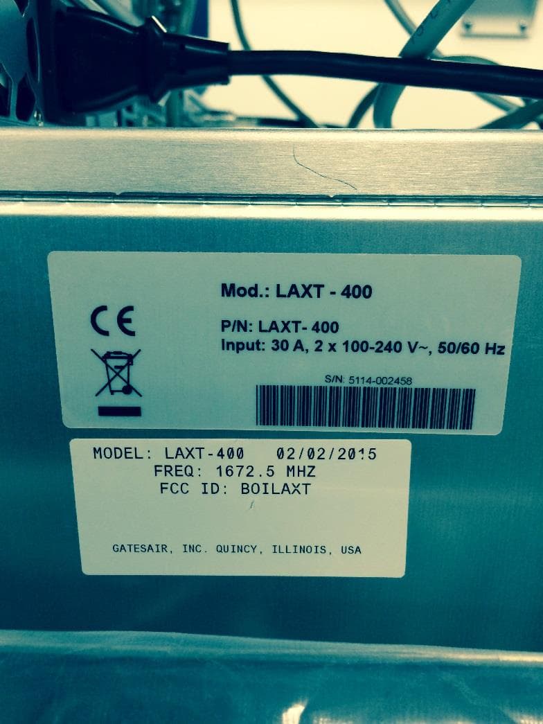
BOILAXT
Apr 23, 2015Maxiva LAXT Digital Television Transmitter
Equipment Class
TNB - Licensed Non-Broadcast Station Transmitter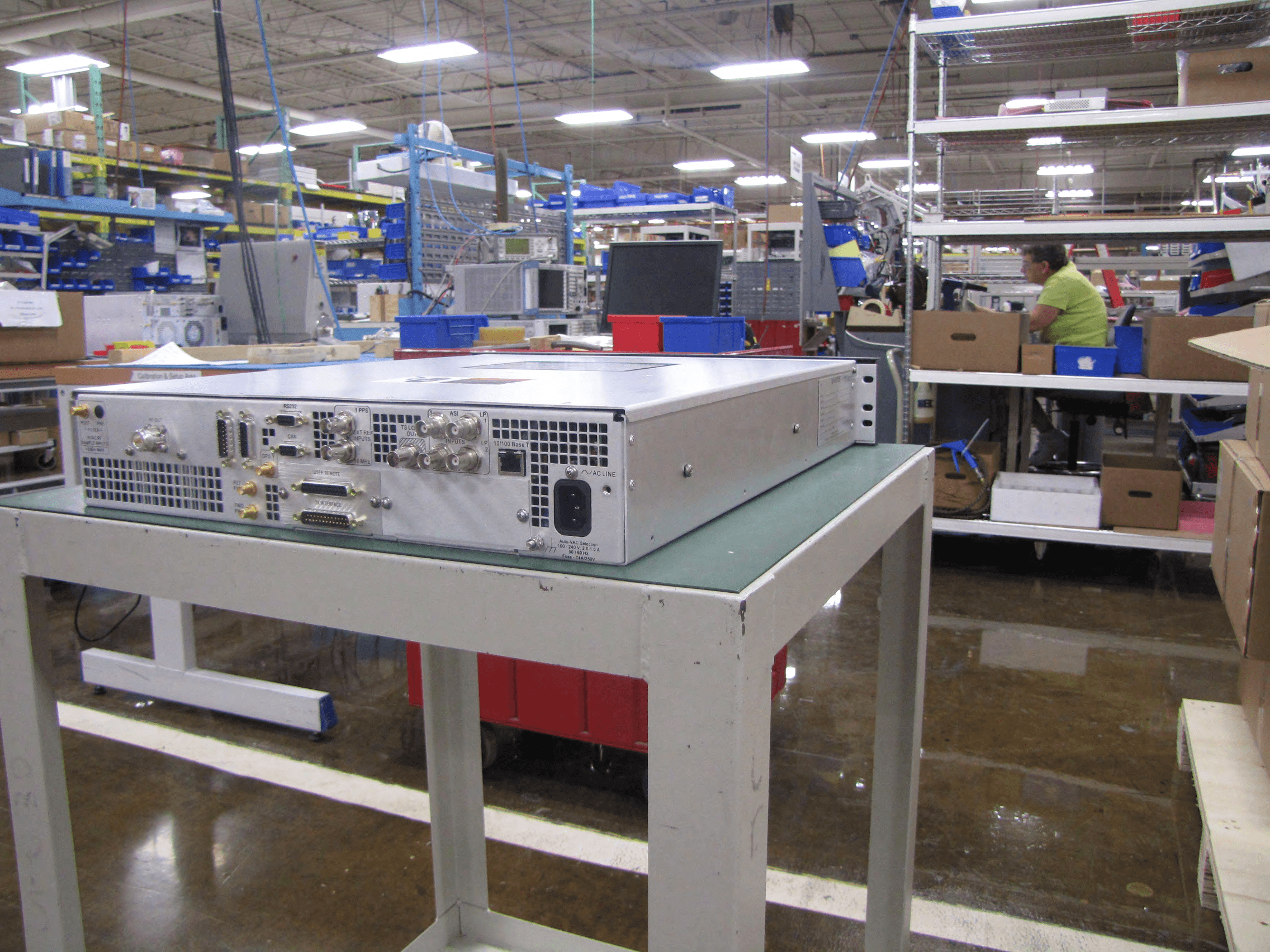
BOIUAXCC
Mar 24, 2014Maxiva Compact Class
Equipment Class
TBC - Licensed Broadcast Station Transmitter
BOIFAXLP
Feb 04, 2014Flexiva Air-Cooled FM Transmitter/Exciter for Analog and Digital Standards Compact Class, Low Power - 50 W to 3.5 kW
Equipment Class
TBC - Licensed Broadcast Station Transmitter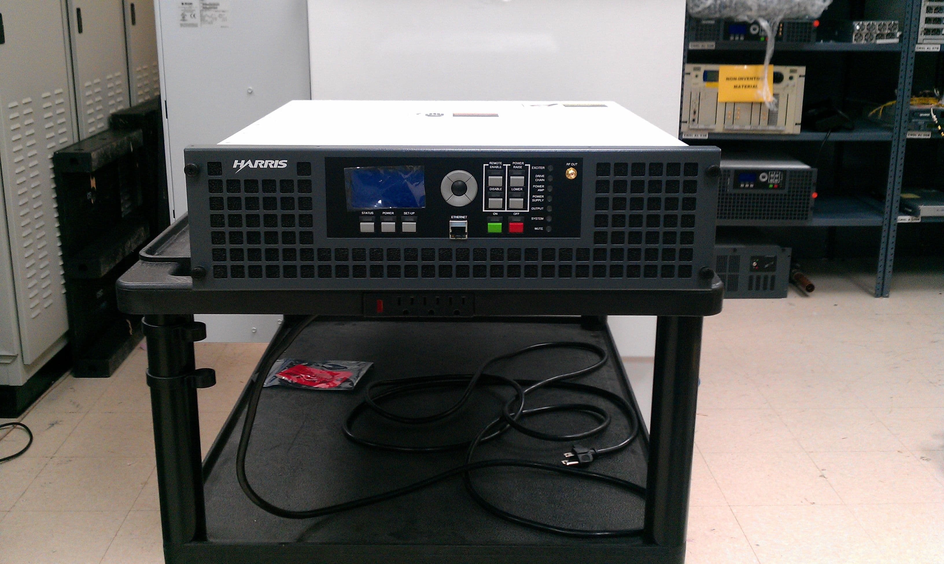
BOIFAXMP
Feb 03, 2014Air-Cooled FM Transmitter for Analog and Digital Standards Compact Class, Low Power
Equipment Class
TBC - Licensed Broadcast Station Transmitter