BOIDVFAtlas Mobile Digital Television Transmitter
GatesAir, Inc.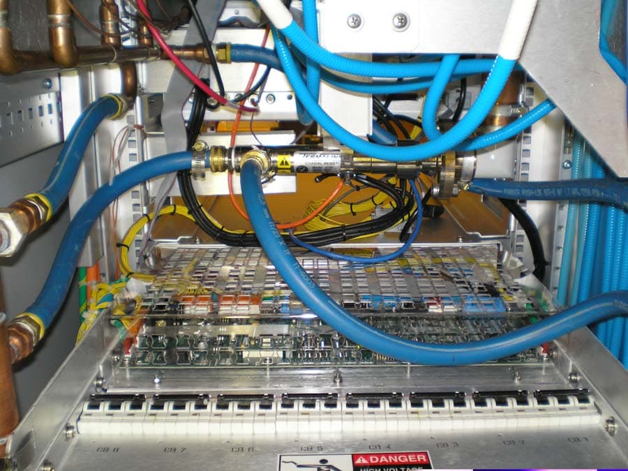
Click to zoom
Application Details
- Equipment Class
- TNB - Licensed Non-Broadcast Station Transmitter
- Date of Grant
- Apr 16, 2007
- Application Purpose
- Original Equipment
- Date of Application
- Mar 26, 2007
- Equipment Note
- Atlas Mobile Digital Television Transmitter
- Frequency Range
- 716.00000000 - 722.00000000
- Company
- GatesAir, Inc.
- Country
- United States
Documents & Files
Document Text
Text extracted from the exhibit documents filed with the FCC. Open a document above to read the original.
Cover Letter(s)
HARRIS CORPORATION Broadcast Communications Division 3200 Wismann Lane Post Office Box 4290 Quincy, IL USA 62305-4290 telephone 1-217-222-8200 www.harris.com March 21, 2007 Compliance Certification Services 47174 Benicia Street Fremont, CA 94538 Attn: Mr. Mike Kuo Dear Mike, This letter and the accompanying test report and documents are in application for FCC Certification of a series of Digital Television transmitters to be operated under the requirements of FCC Part 27.53 (f). Three models of the ATLAS Mobile DVF series of transmitters are included in this application, with power output ratings from 900 watts to 3400 watts, before the output filter. All models use the identical sub- assemblies, with the only significant difference between them being the number of output amplifier modules used to produce the required power. The ATLAS Mobile DVF series of transmitters are an advanced modular design, using the same components and assemblies in a building-block approach to create transmitters with output power ratings from 900 watts to 3400 watts at the cabinet output connection. The number of PA (Power Amplifier) modules used is governed by the power output of each model. 2 PA modules are used in the DVF900 transmitter, 4 modules in the 1700 watt DVF1700 and 8 modules in the 3400 watt DVF3400. A single cabinet houses all models up to and including the DVF3400. Larger transmitters are intended using multiple cabinets, and these will be the subject of future applications for Certification. Our test report intends to show that however many PA modules are used, the performance of the transmitter is well within the limits imposed by Part 27.53 (f). Tests were conducted on a single 3400 watt model, the DVF3400. A front and rear photo on page 8 of the test report give details of the various parts of the transmitter. These data are submitted in support of the application for FCC authorization of these three models of the ATLAS Mobile product, under the required Certification method. We respectfully request these products be certified. Yours sincerely, Karl Black Compliance Engineer Harris Broadcast Communications (217) 221-7543
Cover Letter(s)
DVF series Transmitter FCC Certification Application HARRIS CORPORATION Broadcast Communications Division 3200 Wismann Lane Post Office Box 4290 Quincy, IL USA 62305-4290 telephone 1-217-222-8200 www.harris.com Application for Equipment Certification Table of Contents SUBMITTED TO: Compliance Certification Services 47174 Benicia Street Fremont, CA 94538 For: Harris Broadcast Communications DVF Series Transmitter Family DVF series Transmitter FCC Certification Application Table of Contents Exhibit Description Confidentiality Requested 1 Cover Letter No 2 Table of Contents No 3 Request for Confidentiality No A Equipment ID Label Plate and Location No B Modulation Description for Atlas Mobile DVF Series Yes C Technical Description of Harris DVF Series No D Installation & Operating Instructions – Atlas Mobile DVF Yes E Installation & Operating Instructions – Apex Mobile Exciter Yes F Tune-Up Instructions No G Schematics and description of circuitry Yes H Atlas Mobile Cabinet Photos No I PA Module (Final Amplifier) Description Yes J DC Voltages and currents to Final Amplifier No K PA Module (Final Amplifier) Photos Yes L Output Bandpass Filter Specification Yes M Test Report – Includes FCC Form 731 Data No ~~~~~~~~~~~~~~~~~~~~~~~~~~~~~~~
Cover Letter(s)
DVF series Transmitter FCC Certification Application HARRIS CORPORATION Broadcast Communications Division 3200 Wismann Lane Post Office Box 4290 Quincy, IL USA 62305-4290 telephone 1-217-222-8200 www.harris.com Request for Confidentiality Pursuant to 47CFR 0.459, we hereby request that the Exhibits marked on the Table of Contents "Confidentiality Requested", and also marked as "Confidential" on their cover pages, be withheld from public inspection. Each Exhibit so-marked contains information of a proprietary nature to our company, and possibly to our customers also. Information which could be obtained from the cited Exhibits, which are commonly known as "Trade Secrets", includes printed circuit trace routing, component selection, RF circuit "broadbanding" techniques, mechanical construction layouts and modulation methods. The confidentiality of such information is carefully guarded within our company, and only shared when further disclosure is restricted by binding agreement. Additional proprietary information is contained within drawings, schematics and equipment configuration instructions, normally supplied to customers only after their purchase of the described equipment. Our customers, after having made such purchases, have no reason to share the documents with other parties and, in some cases, may be restricted from doing so by binding agreement. Additionally, those documents are normally supplied as hard copies as part of the equipment's documentation, and often in a size that is difficult to duplicate with standard office equipment. We are therefore concerned that in the event the above described information were to be made available in a public forum, particularly one as easy to access as the World Wide Web, our competitors, or those of our customers, could easily obtain and use it to compromise our ability, and that of our customers, to maintain our respective competitive positions in the marketplace worldwide. We therefore respectfully ask that you honor our request to maintain that confidentiality in regard to the selected documents. To support the requested confidentiality, we have placed the information requested to be kept confidential in Exhibits whose cover pages and whose entries in the Table of Contents are marked as described above. Sincerely, Karl Black Compliance Engineer (217) 221-7543 (office) (217) 221-7088 (fax) [email protected]
Cover Letter(s)
http://mail.google.com/mail/?view=page&name=gp&ver=sh3fib53pgpk Fwd: Response to Inquiry to FCC (Tracking Number 734641) (Harris BOIDVF AN07T6475) Reply from Tim Dwyer <[email protected]> hide details 11:36 am (2 minutes ago) to Mike Kuo <[email protected]> date Apr 17, 2007 11:36 AM subject Fwd: Response to Inquiry to FCC (Tracking Number 734641) (Harris BOIDVF AN07T6475) mailed-by gmail.com The FCCID in the subject of the previous email was incorrect. It should be BOIDVF. ---------- Forwarded message ---------- From: Tim Dwyer < [email protected]> Date: Apr 17, 2007 11:32 AM Subject: Fwd: Response to Inquiry to FCC (Tracking Number 734641) (Harris BIODVF AN07T6475) To: Mike Kuo < [email protected] > Good Morning Mike, The attached email from FCC indicates that it is ok to issue the grant. I have uploaded this email to the FCC upload folder. Best regards, Tim ---------- Forwarded message ---------- From: Generic Office of Engineering Technology < [email protected] > Date: Apr 17, 2007 11:02 AM Subject: Response to Inquiry to FCC (Tracking Number 734641) To: [email protected] Inquiry: ---Reply from Customer on 04/11/2007--- Harris has agreed to remove the powers above what was actually tested. The grant will show only powers at and below what was tested. Harris understands that they will need to submit a separate filing for the higher power model(s) if/when needed. Are the remaining inquiry items considered complete so as to allow the grant to be issued? Response: The equipment as reported shows compliance, and is acceptable for grant of Certification. http://mail.google.com/mail/?view=page&name=gp&ver=sh3fib53pgpk 4/17/2007 11:39:26 AM
External Photos
DVF series Transmitter FCC Certification Application HARRIS CORPORATION Broadcast Communications Division 3200 Wismann Lane Post Office Box 4290 Quincy, IL USA 62305-4290 telephone 1-217-222-8200 www.harris.com Application for Equipment Certification EXHIBIT H ATLAS Mobile Cabinet Photos 1. Overall photos Photos of the DVF3400 transmitter can be seen in EXHIBIT M – TEST REPORT, on pages 7, 9 and 10. 2. Cabinet Internal Photos This set of photos shows detailed views of the RF I/O distribution and the liquid coolant distribution to and from the PA (Power Amplifier) modules. PA Module RF Input and Control Connections The photo is of the RF splitter assembly and the distribution of control signals to the PA (Power Amplifier) Modules . DVF series Transmitter FCC Certification Application RF Combiners and Reject Loads This photo of the rear upper area of the cabinet shows the two 3dB 4-way combining assemblies, above each other at the center, and the RF Load cooling plate on the left. Coolant lines from the cabinet connection points at the top of the cabinet can be seen at the left and the right. Coolant is distributed to all modules and to a cooling plate on which are mounted the reject loads. DVF series Transmitter FCC Certification Application Reject Load Cooling Plate This photo is of the reject loads mounted on the cooling plate. DVF series Transmitter FCC Certification Application Main Reject Load A single 3 dB combiner combines the outputs of the two 4-way hybrid combiners. The reject load for the single 3 dB combiner is shown mounted horizonally, with coolant lines connected. DVF series Transmitter FCC Certification Application Liquid Coolant Distribution In this photo, the coolant distribution to the input and output connections of the either modules can be seen.
ID Label/Location Info
DVF series Transmitter FCC Certification Application HARRIS CORPORATION Broadcast Communications Division 3200 Wismann Lane Post Office Box 4290 Quincy, IL USA 62305-4290 telephone 1-217-222-8200 www.harris.com Application for Equipment Certification EXHIBIT A Equipment ID Label Plate and Location 2.1033 (c) (11) Identification Plate A photograph or drawing of the equipment identification plate or label showing the information to be placed thereon . Example of Identification Plate to be attached to the DVF3400 Transmitter MODEL:DATE: PART NO:FCC ID: SERIAL NO:OTHER ID: FREQUENCY:MHZ CHANNEL: POWER OUT:3.4KWXAVGPK VAC3PHASE60HZ UHF Channel 55 208 DVF3400 995-0072-001 OPD0001-060806 6/8/2006 BOIDVF 716 - 722 The plate is metal and is engraved as shown here. It is riveted to the DVF3400 and other models of the series in the location on rear door shown on the following page. DVF series Transmitter FCC Certification Application
Operational Description
DVF series Transmitter FCC Certification Application HARRIS CORPORATION Broadcast Communications Division 3200 Wismann Lane Post Office Box 4290 Quincy, IL USA 62305-4290 telephone 1-217-222-8200 www.harris.com Application for Equipment Certification EXHIBIT J DC Voltages and Currents of Final Amplifier 2.1033 (c) (8) Final amplifier DC voltages & currents The dc voltages applied to and dc currents into the several elements of the final radio frequency amplifying device for normal operation over the power range. The DV3400F transmitter uses eight solid state power amplifiers per cabinet. The operating RF output power per amplifier is 445W. The voltages and currents for one PA module the DVF3400 are shown below, A display screen from the transmitter has been captured to show the required data. The supply voltage and the currents of all 8 module pallets are shown. From this data, it may be seen that the supply voltage of this PA module is 30.5V. The total PA current for this module is the sum of the pallet currents, 60.0 A.
Parts List/Tune Up Info
DVF series Transmitter FCC Certification Application HARRIS CORPORATION Broadcast Communications Division 3200 Wismann Lane Post Office Box 4290 Quincy, IL USA 62305-4290 telephone 1-217-222-8200 www.harris.com Application for Equipment Certification EXHIBIT F Tune-Up, Installation and Operating Instructions Harris DVF series Transmitters The Harris DVF series transmitters are entirely solid-state and broadband. Tune-up in the conventional sense does not exist for these transmitters. However there are certain adjustments which may be carried out as needed by the user. These are described in detail in the two technical manuals included with this application as EXHIBITS D and E. EXHIBIT D – Installation and Operating Instructions – Atlas Mobile DVF Full installation instructions for the transmitter are in EXHIBIT D, Section 2, pages 2-1 through 2-43. Operating Instructions are in Section 3 of EXHIBIT D. EXHIBIT E – Installation & Operating Instructions – Apex Mobile Exciter Installation instructions for the exciter are located in Section 2, pages 2-1 through 2-11. The Exciter is operated as a part of the transmitter, but information on operating features and procedures for the exciter are included in Section 3, pages 3-1 through 3- 54. ~~~~~~~~~~~~~~~~~~~~~~~~~~~~~~
Test Report
DVF series Transmitter FCC Certification Application HARRIS CORPORATION Broadcast Communications Division 3200 Wismann Lane Post Office Box 4290 Quincy, IL USA 62305-4290 telephone 1-217-222-8200 www.harris.com Application for Equipment Certification EXHIBIT C Technical Description Harris DVF Series DTV Transmitters 2.1033 (c) (4) Type or Types of emission, 6M00W7W 2.1033 (c) (5) Frequency Range As ATLAS Mobile transmitters, the DVF series of transmitters will operate at 719 MHz, with a channel bandwidth of 6 MHz. 2.1033 (c) (6) Range of operating power A series of transmitter models of identical design except for the power levels is submitted by this application. Operating powers will be from 900 Watts to 10,000 Watts average power. The transmitters will operate in Single-Frequency networks with the power level of each site determined by the local conditions and the coverage needs of the network. Transmitter models will be selected by the licensee to meet those needs. The model selected for each location will be the lowest power model meeting the needs of the location. These transmitters are provided with power regulation to hold them to the power output level setting. Power output can be changed, either by front panel adjustment, or by a remote control adjustment, as a means to maintain the desired output power. 2.1033 (c) (7) Maximum Power For this series of transmitters, the maximum rated power is 10,000 Watts.
Test Report
Certification of Compliance ATLAS™ MOBILE Digital TV Transmitter for FCC Title 47 This document is compiled to provide the data and records supporting a Certification of Compliance with FCC Rules set forth in 47CFR Parts 2 and 27. Certification as described in Part 2, Subpart J applies to all subsequent identical units marketed. Use of the Certification method requires that the required records are filed accompanying FCC Form 731. The test record shall be retained as required by 2.938(c). The transmitter tested is referred to by Harris as: Trade Name ATLAS™ MOBILE FCC Identifier BOIDVF Frequency 719 MHz Model: Rated Power Before Filters DVF900 900 Watts DVF1700 1700 Watts DVF3400 (Tested) 3400 Watts Serial Number OPD0001-060806 Sample Tested: DVF3400 3400 Watts Before Output Filters 3000 Watts After Output Filters These tests were conducted and documented by: Page 1 of 36 ________________________________________ March 20, 2007 Sal Mendez (Date) Project Engineer The person responsible for testing is: ________________________________________ March 20, 2007 Karl Black (Date) Compliance Engineer Page 2 of 36 Table of Contents As an aid to locating needed information in this document, the following Table of Contents links each portion of the record with the appropriate Rule and locates it in this document by page number. Rule # Page Rules and Standards Applied in these Measurements.................................................................................... 3 Test Equipment Used in these Measurements................................................................................................ 3 2.938 Retention of records................................................................................................................... 4 (a) Records to be maintained............................................................................................................ 4 (1) Original Design Drawings and Specifications........................................................................... 4 (2) Production Testing and Inspection Procedures......................................................................... 4 (3) Test Results Demonstrating Compliance................................................................................... 4 (c) Record retention period.............................................................................................................. 4 2.1033 Application for certification....................................................................................................... 5 (a) Filed on FCC Form 731.............................................................................................................. 5 (c) Contents of Technical Report..................................................................................................... 5 (1) Name and address of manufacturer........................................................................................... 5 (2) FCC Identifier............................................................................................................................ 5 (3) Installation and operating instructions....................................................................................... 5 (4) Type or Types of emission,....................................................................................................... 5 (5) Frequency Range....................................................................................................................... 5 (6) Range of operating power......................................................................................................... 5 (7) Maximum Power....................................................................................................................... 6 (8) Final amplifier DC voltages & currents..................................................................................... 6 (9) Tune-up procedure.................................................................................................................... 6 (10) Schematics & Circuit descriptions............................................................................................. 7 (11) Identification Plate..................................................................................................................... 7 (12) Photographs of equipment......................................................................................................... 8 (13) Description of digital modulation............................................................................................ 14 (14) Required Data, 2.1046 through 2.1057................................................................................... 14 2.1046 Measurements required: RF power output............................................................................... 15 27.53 Emission limits............................................................................................................................ 17 2.1047 Measurements required: Modulation characteristics................................................................ 17 2.1049 Measurements required: Occupied bandwidth......................................................................... 24 2.1057 Frequency spectrum to be investigated..................................................................................... 25 2.1051 Measurements required: Spurious emissions at antenna terminals........................................... 27 2.1053 Measurements required: Field strength of spurious radiation.................................................. 30 2.1055 Measurements required: Frequency stability............................................................................ 35 Page 3 of 36 Rules and Standards Applied in these Measurements Requirement: Standard / Procedure 2.1046(a), (c) wer Output The output power at the transmitter output flange and at the output from the output bandpass filter were…
Text truncated - open the document above for the full version.
Contact Information
Applicant
John R Harmon(Compliance Engineer)
Technical Specifications
| # | Rule Parts | Frequency Range | Power Output | Emission | Tolerance |
|---|---|---|---|---|---|
| 3 | 27 | 716 MHz - 722 MHz | 3400 W | 6M00W7W | 0.719 Hz |
Other Applications from GatesAir, Inc.
BOI-GXLP300
Dec 04, 2024LPFM Transmitter
Equipment Class
TBC - Licensed Broadcast Station Transmitter
BOILAXT
Apr 23, 2015Maxiva LAXT Digital Television Transmitter
Equipment Class
TNB - Licensed Non-Broadcast Station Transmitter
BOIUAXCC
Mar 24, 2014Maxiva Compact Class
Equipment Class
TBC - Licensed Broadcast Station Transmitter
BOIFAXLP
Feb 04, 2014Flexiva Air-Cooled FM Transmitter/Exciter for Analog and Digital Standards Compact Class, Low Power - 50 W to 3.5 kW
Equipment Class
TBC - Licensed Broadcast Station Transmitter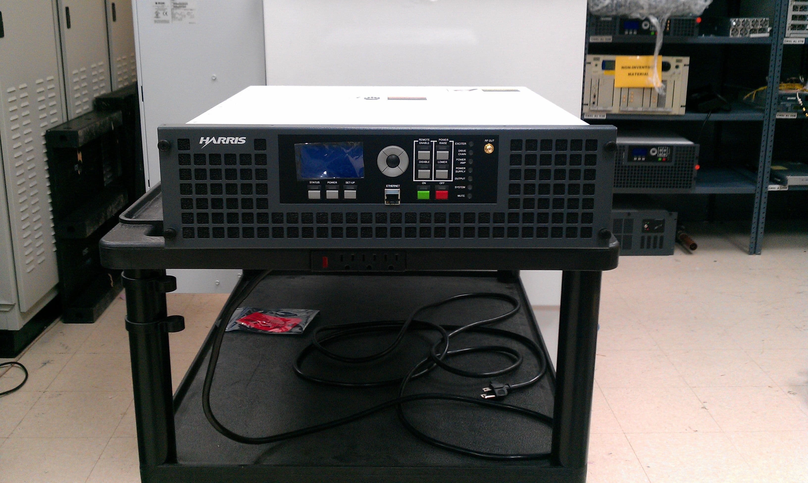
BOIFAXMP
Feb 03, 2014Air-Cooled FM Transmitter for Analog and Digital Standards Compact Class, Low Power
Equipment Class
TBC - Licensed Broadcast Station Transmitter