BOIDVMCool Play 1670 DVM Digital Television Transmitter
GatesAir, Inc.Application Details
- Equipment Class
- TNB - Licensed Non-Broadcast Station Transmitter
- Date of Grant
- May 07, 2007
- Application Purpose
- Original Equipment
- Date of Application
- May 07, 2007
- Equipment Note
- Cool Play 1670 DVM Digital Television Transmitter
- Frequency Range
- 1672.50000000 - 1672.50000000
- Company
- GatesAir, Inc.
- Country
- United States
Documents & Files
Document Text
Text extracted from the exhibit documents filed with the FCC. Open a document above to read the original.
Cover Letter(s)
HARRIS CORPORATION Broadcast Communications Division 3200 Wismann Lane Post Office Box 4290 Quincy, IL USA 62305-4290 telephone 1-217-222-8200 www.harris.com April 30, 2007 Compliance Certification Services 47174 Benicia Street Fremont, CA 94538 Attn: Mr. Mike Kuo Dear Mike, This letter and the accompanying test report and documents are in application for FCC Certification of a series of Digital Television transmitters to be operated under the requirements of FCC Part 27.53 (j). Eight models of the CoolPlay 1670 DVM series of transmitters are included in this application, with power output ratings from 25 watts to 400 watts, after the output filter. All models use identical sub-assemblies, with the only significant difference between them being that the 400W system uses a combiner and the other system could have single or dual outputs to achieve the desired power levels. The other significant difference being the number of output amplifier modules used to produce the required power. The CoolPlay 1670, DVM series of transmitters are an advanced modular design, using the same components and assemblies in a building-block approach to create transmitters with output power ratings from 25 watts to 400 watts at the cabinet output connection or connections. The unit has two variants one with a single output with output levels of 50, 100, 200, 400 watts and the second variant has two outputs each with output powers of 25, 50, 100, 200. The number of PA (Power Amplifier) modules and filters used is governed by the power output of each model. For the single output system, 1 PA module and 1 filter is used in the DVM50, DVM100 transmitter, 2 PA modules and 1 filter are used in the DVM200 and 4 PA modules and two filters are used in the 400 watt DVM400. For the dual output system, 2 PA module and 2 filters are used in the DVM50D (two outputs of 25W ea.), DVM100D (two outputs of 50W ea.) transmitters, 2 PA modules and 2 filters are used in the DVM200D (two outputs of 100W ea.) and 4 PA modules and 2 filters are used in the DVM400D (two outputs of 200W ea.). A single cabinet houses each model. Our test report intends to show that however many PA modules are used, the performance of the transmitter is well within the limits imposed by Part 27.53 (j). Tests were conducted on a single 400 watt model, the DVM400. This is the highest output power level offered in this series of transmitters. These tests are also asserted to be typical of the performance to be had from lower power versions of the same transmitter. A front and rear photo on page 7 of the test report give details of the various parts of the transmitter. Justification for Certifying these eight transmitter models as a group Modern solid-state transmitters are highly modular in design. Where parallel output amplifier modules are used to arrive at the desired output power, the principal emission characteristics are established by the amplifier modules themselves. If the overall transmitter structure is identical for several different power levels, in which the only change is to alter the number of modules combined together, performance of the various models at the various power levels will be consistent. Harris Broadcast Communications has obtained confirmation in previous years from FCC contacts that this is a valid concept, and recently we received the following eMail in response to an inquiry about the current designs: 2 From: Joe Dichoso [mailto:[email protected] ] Sent: Thursday, October 12, 2006 8:59 AM To: Hanna, Tania Cc: Rashmi Doshi; Steven Dayhoff; Andrew Leimer; Joe Dichoso Subject: RE: Hello Tania, Below is our reply to your inquiry. Please let us know if you have any issues with it or not. Thanks, Joe Rack mounted transmitters with stacked amplifier modules under one FCC identifier is allowed under the following conditions. 1) The amplifier modules are identical in design. 2) The addition or deletion of the modules changes only the output power. 3) The frequency range of different models with different modules is identical. There are no changes in the frequency operational range or determining circuitry between the different models with different installed modules. 4) For Certification submittals, each rack is tested with the maximum number of modules installed. While only the full rack is tested and submitted, the grantee is responsible for compliance for all configurations. Also, a separate line item should be added for each combination (e.g.: 1, 2, or 3 identical "stacked" power amplifiers would have 3 line items). Additional info: Section 2.1043 does not allow a change in maximum output power, therefore a a C2PC would not be allowed to add modules to increase output power beyond the configurations in the original application. Also, Section 2.1403 does not allow a change in frequency determining or output power circuitry, therefore non-identical plug-in modules other than the original module cannot be added with a C2PC. We believe these current DVM series CoolPlay 1670 transmitters meet the above requirements. • All of the amplifier modules used are identical. • Adding or deleting modules does change only the output power. • The frequency range of all will be identical. The service for which the CoolPlay 1670 transmitters have been designed to operates on a single TV channel everywhere, as Single Frequency Networks of transmitters to supply TV signals to mobile devices such as cellular telephones. • Therefore, we have tested at the maximum power possible in this service, by using the DVM400. • The output power circuitry (PA Modules) and the frequency determining circuitry in the exciter) all models of this transmitter series. Therefore, these data are submitted in support of the application for FCC authorization of these eight models of the CoolPlay 1670 product, under the required Certification method. We respectfully request these products be certified. Yours sincerely, Karl Black Compliance Engineer 3 Harris Broadcast Commun…
Text truncated - open the document above for the full version.
Cover Letter(s)
CoolPlay 1670 Transmitter FCC Certification Application HARRIS CORPORATION Broadcast Communications Division 3200 Wismann Lane Post Office Box 4290 Quincy, IL USA 62305-4290 telephone 1-217-222-8200 www.harris.com Table of Contents Confidentiality Requested 1. Cover Letter NO 2. Table of Contents NO 3. Request for Confidentiality NO A. Equipment ID Label Plate and mounting location NO B. Modulation Description NO C. Technical Description NO D. Installation and Operating Instructions, CoolPlay 1670 DVM Transmitters YES E. Installation and Operating Instructions, CoolPlay 1670 UBS Exciter YES F. Tuning Up Procedure YES G. Schematics and Description of Circuits YES H. CoolPlay 1670 Cabinet Photos YES I. PA Module (Final Amplifier) Description YES J. DC Voltages and Currents of Final Amplifiers NO K. PA Module (Final Amplifier) Photos YES L. Output Bandpass Filter Specification YES M. Test Report NO
Cover Letter(s)
http://mail.google.com/mail/?view=page&name=gp&ver=sh3fib53pgpk BOITNB CCS Application AN07T6772 Inbox Reply Tim Dwyer to Karl, Paul show details May 1 (6 days ago) Paul, Karl, I see you have entered a new application. I will probably pick this one up. On the application form there are no entries for frequency, power, emission designator, etc. If you had trouble with the form, let me know what you want entered and I can do it for you instead of starting over with a new form and project number. Also, I see that you used entered TNB for the product part of the FCCID and wonder if that is really what you want to do. You can also call me at 860-558-1791. Best regards, Tim Reply Reply to all Forward Reply "Black, Karl" to Tim, Paul show details May 1 (6 days ago) Tim, Thanks for the quick response. This one is really pretty important, and we need to do what we can to move it forward rapidly. We'd appreciate your making the needed corrections: l Frequency of these transmitters is 1672.5 MHz. They will all operate on one 5 MHz channel centered at that frequency, in single- frequency networks. l Power output level of these transmitters varies from 25 watts to 400 watts. We will submit a test report of the 400 watt model as typical of all of them. l The emission designator is 5M00W7W. l BOITNB is wrong. The full FCC ID should be BOIDVM. The technical manual for the transmitter is a pdf file larger than 7 MB. Reduce File size did not bring it below 4 MB, as there are photos in it which will not reduce, so Tech Pubs is making me a two-part version to get the individual parts below 4 MB. I should be able to upload it and the remaining files today. The test report will be uploaded last of all, as it is being competed now. http://mail.google.com/mail/?view=page&name=gp&ver=sh3fib53pgpk (1 of 4)5/7/2007 1:44:08 PM http://mail.google.com/mail/?view=page&name=gp&ver=sh3fib53pgpk The Equipment Specifications block as I entered it is attached as App7.gif - possibly I failed to SAVE. The initial files upload was as in Upload1.gif, attached. I just received your eMail confirming you see the files I just now uploaded, which tells me I must have failed to take some step earlier, so I'll upload those again as soon as I have the manual size problem resolved. . Thanks for your help on this, Tim. Karl Black From: [email protected] [mailto:[email protected]] On Behalf Of Tim Dwyer Sent: Tuesday, May 01, 2007 8:16 AM To: Black, Karl; Mizwicki, Paul Subject: BOITNB CCS Application AN07T6772 - Show quoted text - 2 attachments — Download all attachments View all images App 7.gif 17K View Download http://mail.google.com/mail/?view=page&name=gp&ver=sh3fib53pgpk (2 of 4)5/7/2007 1:44:08 PM http://mail.google.com/mail/?view=page&name=gp&ver=sh3fib53pgpk Upload 1.gif 23K View Download Reply Reply to all Forward Invite Karl to Gmail Reply Tim Dwyer to Karl show details May 1 (6 days ago) Karl, Got it. I am going to wait until this afternoon to see if maybe the form completes when all the files show up. I see that you uploaded more documents than are showing at the moment, so apparently they show up one at a time or in groups after whatever processing gets done. I'll keep checking. Tim - Show quoted text - Reply Forward Reply "Black, Karl" to Tim, Paul show details May 1 (5 days ago) Tim, All the files are now uploaded except for the test report, which will be forthcoming. If it won't violate your Rules of Engagement, we'd appreciate getting review of what we've provided as soon as is feasible, and if there is a charge for faster action I know there's be no problem with the added cost (I did not check the box for that, but we can handle that). The reduce file size function did not make the one manual (D) small enough, so we broke the manual into three sections at logical break points and I put a cover page on each identifying its contents. Please let us know of anything you see which we ought to change. In most cases, Paul is the best first contact, but if you need to contact me, feel free. http://mail.google.com/mail/?view=page&name=gp&ver=sh3fib53pgpk (3 of 4)5/7/2007 1:44:08 PM http://mail.google.com/mail/?view=page&name=gp&ver=sh3fib53pgpk Best Regards, Karl Black Compliance Engineer Harris Broadcast Communications http://mail.google.com/mail/?view=page&name=gp&ver=sh3fib53pgpk (4 of 4)5/7/2007 1:44:08 PM http://mail.google.com/mail/?ik=2a69a1bf8a&view=cv&search=query&q=harris&th=1125393e0a52257f&ww=1131&cvap=2&qt=harris.0&zx=pifwxuuyo6b7 Harris Corporation - Broadcast Communication Division, FCC ID: BOIDVM, Assessment NO.: AN07T6772, Notice#1 Inbox Reply "[email protected]" to kblack, pmizwick show details May 2 (5 days ago) Hello Karl, At your request, a preliminary review has been performed of the application package including exhibits 1-3 and A-L. The application documents appear to be complete and acceptable. We are awaiting upload of the test report. Insofar as final review requires comparison of information in the test report with the other exhibits, the project is in pending status until a review of all documents including the test report can be completed. Please notify me by email when the test report is uploaded and in case any additional or revised exhibits are submitted. As always, if there are any questions, please ask. Best regards, Tim Dwyer CCS Technical Reviewer The items indicated above must be submitted before processing can continue on the above referenced application. Failure to provide the requested information within 30 days of the original e-mail date may result in application dismissal and forfeiture of the filing fee. Also, please note that partial responses increase processing time and should not be submitted. Any questions about the content of this correspondence should be directed to the e-mail address listed below the name of the sender. Reply Reply to all Forward Invite [email protected] to Gmail Reply "Mizwicki, Paul" to tim.dwyer, Karl show details May 2 (5 days ago) Tim, Thank…
Text truncated - open the document above for the full version.
External Photos
CoolPlay 1670 DVM Transmitter FCC Certification Application HARRIS CORPORATION Broadcast Communications Division 3200 Wismann Lane Post Office Box 4290 Quincy, IL USA 62305-4290 telephone 1-217-222-8200 www.harris.com Application for Equipment Certification EXHIBIT H CoolPlay 1670 Cabinet Photos Confidential ~~~~~~~~~~~~~~~~~~~~~~~~~~~ Several photos and descriptions of the CoolPlay 1670 DVM series of transmitters can be seen in EXHIBIT D – Installation and Operating Instructions for the CoolPlay 1670 DVM Series of transmitters. The detailed cabinet photos can be seen throughout the technical manual but preliminary one should look in section 1.2.2 of the CoolPlay technical manual.
ID Label/Location Info
CoolPlay 1670 DVM Transmitter FCC Certification Application HARRIS CORPORATION Broadcast Communications Division 3200 Wismann Lane Post Office Box 4290 Quincy, IL USA 62305-4290 telephone 1-217-222-8200 www.harris.com Application for Equipment Certification EXHIBIT A Equipment ID Label Plate and Mounting Location 2.1033 (c) (11) Identification Plate A photograph or drawing of the equipment identification plate or label showing the information to be placed thereon. The Equipment ID Label is engraved on a metal plate along with product identification information. The plate is installed in a suitable location on each transmitter. I. Example of Identification Plate to be attached to the CoolPlay DVM Transmitter 2. Location of ID plate on the CoolPlay 1670 DVM Transmitter The metal plate that is riveted to the DVM400 or other models of this series is location inside the backdoor of the cabinet since this transmitter is an outdoor unit. This protects the metal plate from vandals and the weather. A photo showing the location of the plate is shown below. MODEL: DATE: PART FCC ID: SERIAL OTHER ID: FREQUENCY: MHZ CHANNEL POWER OUT: .400WXAVPK VASINGLEPHAS 60 HZ SFN 208 DVM400 995 0032 001 OPD00001-060806 6/8/2006 BOIDVM 1670 - 1675 CoolPlay 1670 DVM Transmitter FCC Certification Application MODEL: DATE: PART NO: FCC ID: SERIAL NO: OTHER ID: FREQUENCY: MHZ CHANNEL: POWER OUT: .400 W X AVG PK VAC SINGLE PHASE 60HZ SFN 208 DVM400 995 0032 001 OPD00001-060806 6/8/2006 BOIDVM 1670 -
Internal Photos
CoolPlay 1670 DVM Transmitter FCC Certification Application HARRIS CORPORATION Broadcast Communications Division 3200 Wismann Lane Post Office Box 4290 Quincy, IL USA 62305-4290 telephone 1-217-222-8200 www.harris.com Application for Equipment Certification EXHIBIT H CoolPlay 1670 Cabinet Photos Confidential ~~~~~~~~~~~~~~~~~~~~~~~~~~~ Several photos and descriptions of the CoolPlay 1670 DVM series of transmitters can be seen in EXHIBIT D – Installation and Operating Instructions for the CoolPlay 1670 DVM Series of transmitters. The detailed cabinet photos can be seen throughout the technical manual but preliminary one should look in section 1.2.2 of the CoolPlay technical manual.
Operational Description
CoolPlay 1670 DVM Transmitter FCC Certification Application HARRIS CORPORATION Broadcast Communications Division 3200 Wismann Lane Post Office Box 4290 Quincy, IL USA 62305-4290 telephone 1-217-222-8200 www.harris.com Application for Equipment Certification EXHIBIT B Modulation Description for CoolPlay 1670 DVM Series of Transmitters The type of modulation used in the CoolPlay 1670 transmitters is DVB-H. This is a COFDM modulation transmission standard. It is fully described in ETSI standard EN 300 744. The particular form of DVB-H transmission intended for this particular use with a channel width of 5 MHz.
Operational Description
CoolPlay 1670 DVM Transmitter FCC Certification Application HARRIS CORPORATION Broadcast Communications Division 3200 Wismann Lane Post Office Box 4290 Quincy, IL USA 62305-4290 telephone 1-217-222-8200 www.harris.com Application for Equipment Certification EXHIBIT C Technical Description For CoolPlay 1670 DVM Series of transmitters 2.1033 (c) (4) Type or Types of emission, 5M00W7W 2.1033 (c) (5) Frequency Range The CoolPlay 1670 DVM series of transmitters will operate at 1672.5 MHz center , with a channel bandwidth of 5 MHz. 2.1033 (c) (6) Range of operating power A series of transmitter models of identical design except for the power levels is submitted by this application. Operating powers will be from 25 Watts to 400 Watts average power. The transmitters will operate in Single-Frequency networks with the power level of each site determined by the local conditions and the coverage needs of the network. Transmitter models will be selected by the licensee to meet those needs. The model selected for each location will be the lowest power model meeting the needs of the location. These transmitters are provided with power regulation to hold them to the power output level setting. Power output can be changed, either by front panel adjustment, or by a remote control adjustment, as a means to maintain the desired output power. 2.1033 (c) (7) Maximum Power For this series of transmitters, the maximum rated power is 400 Watts.
Operational Description
CoolPlay 1670 DVM Transmitter FCC Certification Application HARRIS CORPORATION Broadcast Communications Division 3200 Wismann Lane Post Office Box 4290 Quincy, IL USA 62305-4290 telephone 1-217-222-8200 www.harris.com Application for Equipment Certification EXHIBIT J DC Voltages and Currents of Final Amplifier 2.1033 (c) (8) Final amplifier DC voltages & currents The dc voltages applied to and dc currents into the several elements of the final radio frequency amplifying device for normal operation over the power range. The DVM400 transmitter uses four solid state power amplifiers per cabinet. The operating RF output power per amplifier is ~250W. The voltages and currents for one Power Amplifier Block on the DVM400 is shown below, A display screen from the transmitter has been captured to show the required data. The supply voltage and the currents of all RF stages are shown. From this data, it may be seen that the supply voltage of this PA module is 32.8V. The total PA module current for this module is the sum of the currents, which is about 20.2A. The total Power Amplifier Block would be about 40.4A.
Test Report
FrequencyPABPFPABPF (MHz)(dB)(dB)linearlinearlinear(dB) 1669-41.15096-31.787.67192E-05 0.0006645.09218E-08-72.93096 1669.01 -41.15096-31.767.67192E-05 0.0006675.11569E-08-72.91096 1669.02 -41.15096-31.737.67192E-05 0.0006715.15115E-08-72.88096 1669.03 -41.15096-31.717.67192E-05 0.0006755.17492E-08-72.86096 1669.04 -41.15096-31.77.67192E-05 0.0006765.18685E-08-72.85096 1669.05 -41.49896-31.77.08115E-05 0.0006764.78745E-08-73.19896 1669.06 -41.49896-31.687.08115E-05 0.0006794.80955E-08-73.17896 1669.07 -41.49896-31.687.08115E-05 0.0006794.80955E-08-73.17896 1669.08 -41.49896-31.677.08115E-05 0.0006814.82063E-08-73.16896 1669.09 -40.98696-31.677.96717E-05 0.0006815.4238E-08-72.65696 1669.1-40.98696-31.687.96717E-05 0.0006795.41133E-08-72.66696 1669.11 -40.98696-31.687.96717E-05 0.0006795.41133E-08-72.66696 1669.12 -40.98696-31.77.96717E-05 0.0006765.38647E-08-72.68696 1669.13 -41.28696-31.717.43539E-05 0.0006755.01538E-08-72.99696 1669.14 -41.28696-31.727.43539E-05 0.0006735.00385E-08-73.00696 1669.15 -41.28696-31.737.43539E-05 0.0006714.99234E-08-73.01696 1669.16 -41.28696-31.757.43539E-05 0.0006684.9694E-08-73.03696 1669.17 -40.97896-31.767.98186E-05 0.0006675.32236E-08-72.73896 1669.18 -40.97896-31.787.98186E-05 0.0006645.2979E-08-72.75896 1669.19 -40.97896-31.837.98186E-05 0.0006565.23726E-08-72.80896 1669.2-40.97896-31.887.98186E-05 0.0006495.17731E-08-72.85896 1669.21 -40.38296-31.929.15596E-05 0.0006435.88442E-08-72.30296 1669.22 -40.38296-31.979.15596E-05 0.0006355.81707E-08-72.35296 1669.23 -40.38296-32.029.15596E-05 0.0006285.75048E-08-72.40296 1669.24 -40.38296-32.079.15596E-05 0.0006215.68465E-08-72.45296 1669.25 -40.38296-32.129.15596E-05 0.0006145.61958E-08-72.50296 1669.26 -41.12596-32.197.71621E-05 0.0006044.66019E-08-73.31596 1669.27 -41.12596-32.297.71621E-050.000594.55412E-08-73.41596 1669.28 -41.12596-32.387.71621E-05 0.0005784.46071E-08-73.50596 1669.29 -41.12596-32.487.71621E-05 0.0005654.35917E-08-73.60596 1669.3-41.03596-32.587.87778E-05 0.0005524.34915E-08-73.61596 1669.31 -41.03596-32.687.87778E-050.000544.25015E-08-73.71596 1669.32 -41.03596-32.797.87778E-05 0.0005264.14385E-08-73.82596 1669.33 -41.03596-32.97.87778E-05 0.0005134.04021E-08-73.93596 1669.34 -40.87296-33.098.17907E-05 0.0004914.01517E-08-73.96296 1669.35 -40.87296-33.278.17907E-05 0.0004713.85216E-08-74.14296 1669.36 -40.87296-33.468.17907E-05 0.0004513.68726E-08-74.33296 1669.37 -40.87296-33.648.17907E-05 0.0004333.53756E-08-74.51296 1669.38 -40.54296-33.838.82478E-05 0.0004143.65346E-08-74.37296 1669.39 -40.54296-34.028.82478E-05 0.0003963.49707E-08-74.56296 1669.4-40.54296-34.218.82478E-05 0.0003793.34737E-08-74.75296 1669.41 -40.54296-34.488.82478E-05 0.0003563.1456E-08-75.02296 1669.42 -40.88796-34.848.15087E-05 0.0003282.67426E-08-75.72796 1669.43 -40.88796-35.28.15087E-05 0.0003022.46152E-08-76.08796 1669.44 -40.88796-35.558.15087E-05 0.0002792.27093E-08-76.43796 1669.45 -40.88796-35.918.15087E-05 0.0002562.09028E-08-76.79796 1669.46 -40.93296-36.278.06685E-05 0.0002361.90416E-08-77.20296 Measured Data Compound 1669.47 -40.93296-36.678.06685E-05 0.0002151.73662E-08-77.60296 1669.48 -40.93296-37.038.06685E-05 0.0001981.59847E-08-77.96296 1669.49 -40.93296-37.818.06685E-05 0.0001661.33568E-08-78.74296 1669.5-40.93296-38.598.06685E-05 0.0001381.1161E-08-79.52296 1669.51 -40.97496-39.397.98921E-05 0.0001159.19399E-09-80.36496 1669.52 -40.97496-40.187.98921E-05 9.59E-057.66486E-09-81.15496 1669.53 -40.97496-40.977.98921E-058E-056.39005E-09-81.94496 1669.54 -40.97496-41.777.98921E-05 6.65E-055.31501E-09-82.74496 1669.55 -41.03796-42.517.87416E-05 5.61E-054.41778E-09-83.54796 1669.56 -41.03796-42.857.87416E-05 5.19E-054.08511E-09-83.88796 1669.57 -41.03796-42.737.87416E-05 5.33E-054.19956E-09-83.76796 1669.58 -41.03796-42.627.87416E-05 5.47E-054.30729E-09-83.65796 1669.59 -40.64096-42.578.62788E-05 5.53E-054.77424E-09-83.21096 1669.6-40.64096-42.468.62788E-05 5.68E-054.89671E-09-83.10096 1669.61 -40.64096-42.368.62788E-05 5.81E-055.01076E-09-83.00096 1669.62 -40.64096-42.258.62788E-05 5.96E-055.1393E-09-82.89096 1669.63 -40.78996-42.198.33689E-05 6.04E-055.03505E-09-82.97996 1669.64 -40.78996-41.048.33689E-05 7.87E-056.56151E-09-81.82996 1669.65 -40.78996-39.898.33689E-05 0.0001038.55075E-09-80.67996 1669.66 -40.78996-38.748.33689E-05 0.0001341.1143E-08-79.52996 1669.67 -40.57296-37.598.76403E-05 0.0001741.52653E-08-78.16296 1669.68 -40.57296-36.448.76403E-05 0.0002271.98932E-08-77.01296 1669.69 -40.57296-35.298.76403E-05 0.0002962.59241E-08-75.86296 1669.7-40.57296-34.148.76403E-05 0.0003853.37835E-08-74.71296 1669.71 -40.56396-33.268.78221E-05 0.0004724.14576E-08-73.82396 1669.72 -40.56396-32.628.78221E-05 0.0005474.80401E-08-73.18396 1669.73 -40.56396-31.998.78221E-05 0.0006325.55398E-08-72.55396 1669.74 -40.56396-31.368.78221E-05 0.0007316.42102E-08-71.92396 1669.75 -40.56396-30.728.78221E-05 0.0008477.44053E-08-71.28396 1669.76 -40.62696-30.078.65574E-05 0.0009848.51734E-08-70.69696 1669.77 -40.62696-29.448.65574E-05 0.0011389.847E-08-70.06696 1669.78 -40.62696-28.88.65574E-05 0.0013181.14105E-07-69.42696 1669.79 -40.62696-28.588.65574E-05 0.0013871.20034E-07-69.20696 1669.8-40.53396-28.368.84309E-05 0.0014591.29004E-07-68.89396 1669.81 -40.53396-28.138.84309E-05 0.0015381.3602E-07-68.66396 1669.82 -40.53396-27.98.84309E-05 0.0016221.43418E-07-68.43396 1669.83 -40.53396-27.678.84309E-050.001711.51218E-07-68.20396 1669.84 -39.92696-27.440.000101696 0.0018031.8336E-07-67.36696 1669.85 -39.92696-27.240.000101696 0.0018881.92001E-07-67.16696 1669.86 -39.92696-27.080.000101696 0.0019591.99207E-07-67.00696 1669.87 -39.92696-270.000101696 0.0019952.0291E-07-66.92696 1669.88 -39.56096-26.920.000110638 0.0020322.24856E-07-66.48096 1669.89 -39.56096-26.830.000110638 0.0020752.29564E-07-66.39096 1669.9-39.56096-26.750.000110638 0.0021132.33832E-07-66.31096 1669.91 -39.56096-26.670.000110638 0.0021532.38179E-07-66.23096 1669.92 -39.86896-26.60.000103063 0.0021882.25478E-07-66.46896 1669.93 -39.86896-26.520…
Text truncated - open the document above for the full version.
Test Report
CoolPlay 1670 DVM Transmitter FCC Certification Application HARRIS CORPORATION Broadcast Communications Division 3200 Wismann Lane Post Office Box 4290 Quincy, IL USA 62305-4290 telephone 1-217-222-8200 www.harris.com EXHIBIT M Test Report The following test report contains the test data to demonstrate compliance. Certification of Compliance Cool Play 1670 Digital TV Transmitter for FCC Title 47 This document is compiled to provide the data and records supporting a Certification of Compliance with FCC Rules set forth in 47CFR Parts 2 and 27. Certification as described in Part 2, Subpart J applies to all subsequent identical units marketed. Use of the Certification method requires that the required records are filed accompanying FCC Form 731. The test record shall be retained as required by 2.938(c). The transmitter tested is referred to by Harris as: Trade Name COOLPLAY TM 1670 FCC Identifier BOIDVM Frequency 1672.5 MHz Model: Rated Power DVM-50 50 Watts DVM-100 100 Watts DVM-200 200 Watts DVM-400 (Tested) 400 Watts DVMD-50 2 x 25 Watts DVMD-100 2 x 50 Watts DVMD-200 2 x 100 Watts DVMD-400 2 x 200 Watts Sample Tested: DVM-400 400 Watts Serial Number OPD0001-060806 The person responsible for testing is: ________________________________________ __May 7, 2007_____ Karl Black (Date) Compliance Engineer Page 1 of 33 Page 2 of 33 Table of Contents As an aid to locating needed information in this document, the following Table of Contents links each portion of the record with the appropriate Rule and locates it in this document by page number. Rule # Page Rules and Standards Applied in these Measurements.................................................................................... 3 Test Equipment Used in these Measurements................................................................................................ 3 2.938 Retention of records................................................................................................................... 3 (a) Records to be maintained............................................................................................................ 3 (1) Original Design Drawings and Specifications........................................................................... 4 (2) Production Testing and Inspection Procedures......................................................................... 4 (3) Test Results Demonstrating Compliance................................................................................... 4 (c) Record retention period.............................................................................................................. 4 2.1033 Application for certification....................................................................................................... 5 (a) Filed on FCC Form 731.............................................................................................................. 5 (c) Contents of Technical Report..................................................................................................... 5 (1) Name and address of manufacturer........................................................................................... 5 (2) FCC Identifier............................................................................................................................ 5 (3) Installation and operating instructions....................................................................................... 5 (4) Type or Types of emission,....................................................................................................... 5 (5) Frequency Range....................................................................................................................... 5 (6) Range of operating power......................................................................................................... 6 (7) Maximum Power....................................................................................................................... 6 (8) Final amplifier DC voltages & currents..................................................................................... 6 (9) Tune-up procedure.................................................................................................................... 7 (10) Schematics & Circuit descriptions............................................................................................. 7 (11) Identification Plate..................................................................................................................... 8 (12) Photographs of equipment......................................................................................................... 8 (13) Description of digital modulation............................................................................................ 16 (14) Required Data, 2.1046 through 2.1057................................................................................... 16 2.1046 Measurements required: RF power output..............................…
Text truncated - open the document above for the full version.
Contact Information
Applicant
John R Harmon(Compliance Engineer)
Technical Specifications
| # | Rule Parts | Frequency Range | Power Output | Emission | Tolerance |
|---|---|---|---|---|---|
| 5 | 27 | 1.67 GHz - 1.67 GHz | 25 W | 5M00W7W | 2 Hz |
Other Applications from GatesAir, Inc.
BOI-GXLP300
Dec 04, 2024LPFM Transmitter
Equipment Class
TBC - Licensed Broadcast Station Transmitter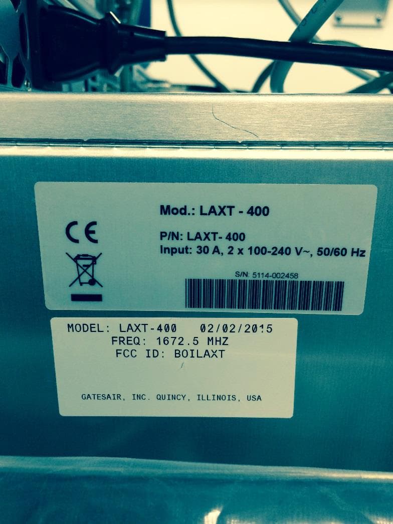
BOILAXT
Apr 23, 2015Maxiva LAXT Digital Television Transmitter
Equipment Class
TNB - Licensed Non-Broadcast Station Transmitter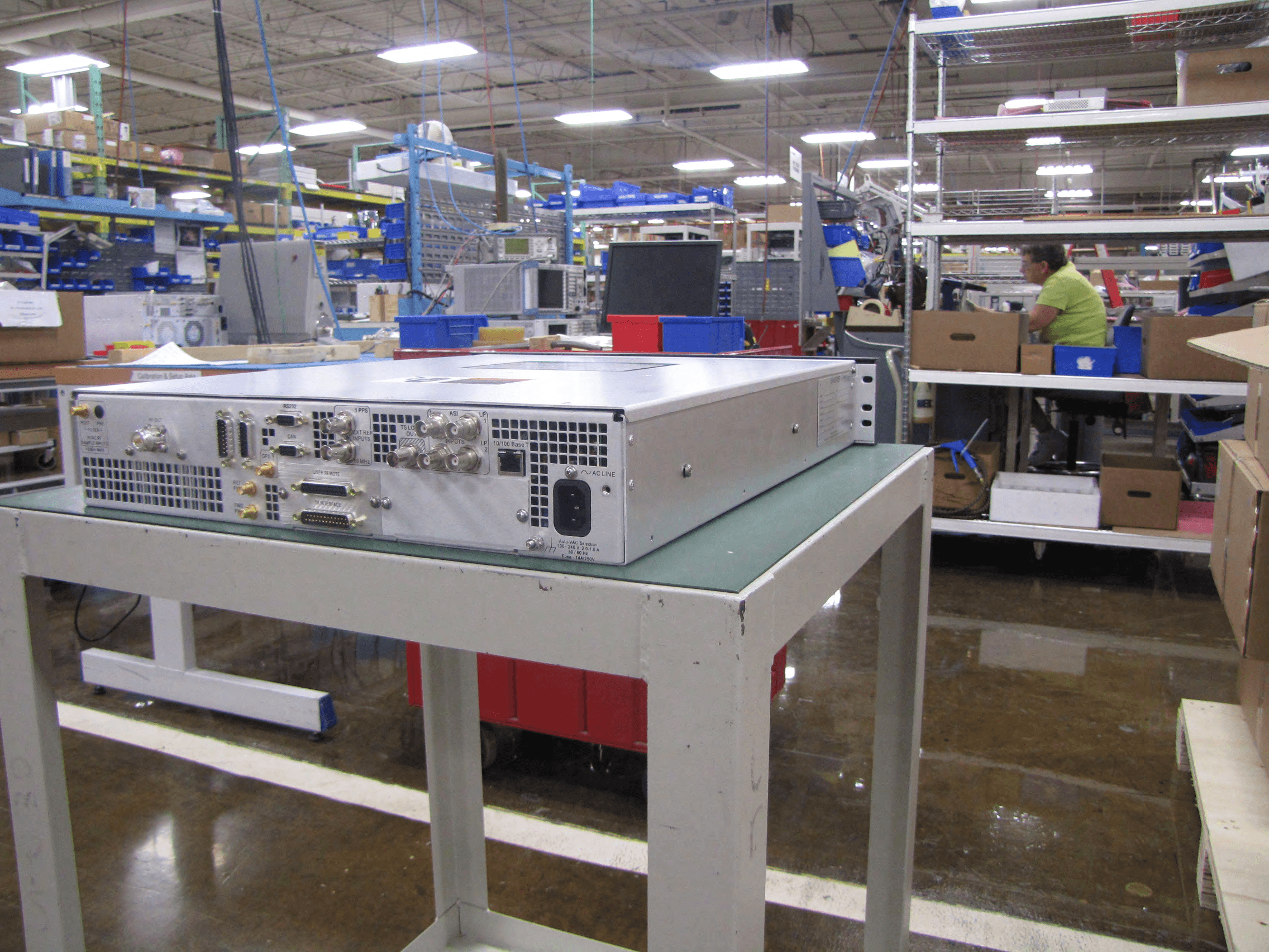
BOIUAXCC
Mar 24, 2014Maxiva Compact Class
Equipment Class
TBC - Licensed Broadcast Station Transmitter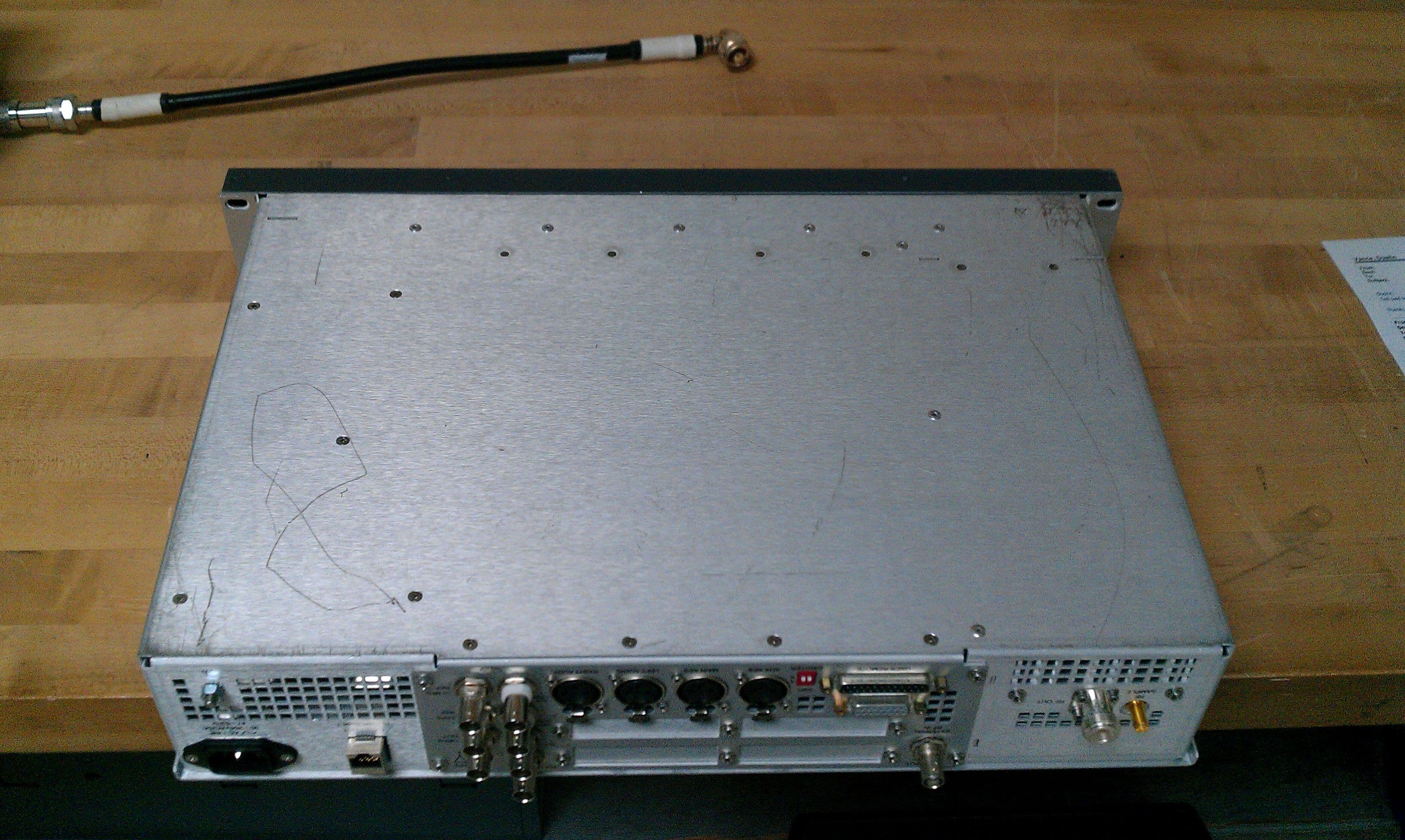
BOIFAXLP
Feb 04, 2014Flexiva Air-Cooled FM Transmitter/Exciter for Analog and Digital Standards Compact Class, Low Power - 50 W to 3.5 kW
Equipment Class
TBC - Licensed Broadcast Station Transmitter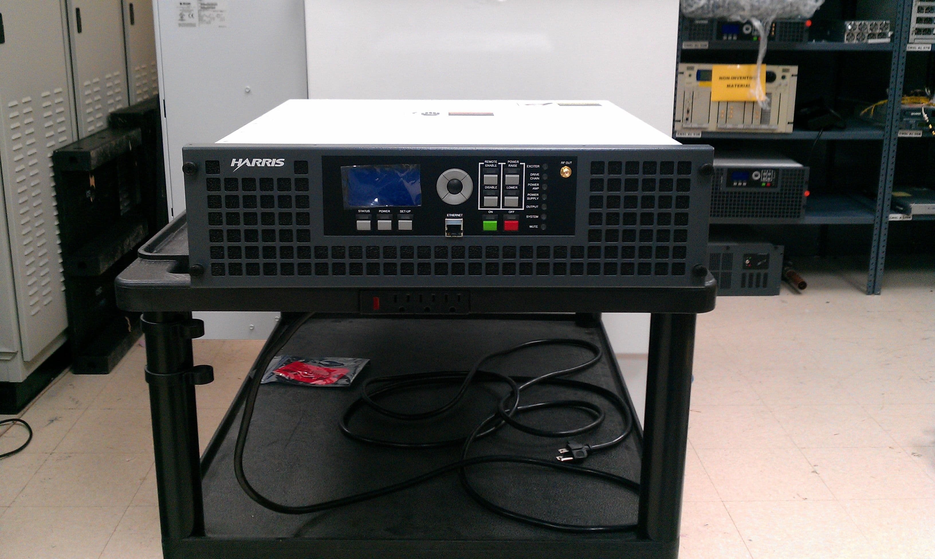
BOIFAXMP
Feb 03, 2014Air-Cooled FM Transmitter for Analog and Digital Standards Compact Class, Low Power
Equipment Class
TBC - Licensed Broadcast Station Transmitter