BV2-AHGC20Bluetooth Headphone
D&M Holdings Inc.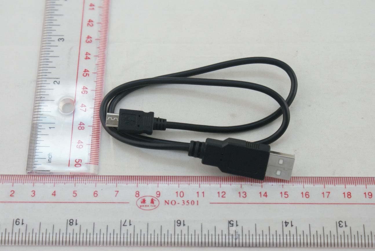
Click to zoom
Application Details
- Equipment Class
- DSS - Part 15 Spread Spectrum Transmitter
- Date of Grant
- Dec 18, 2014
- Application Purpose
- Original Equipment
- Date of Application
- Dec 18, 2014
- Equipment Note
- Bluetooth Headphone
- Frequency Range
- 2402.00000000 - 2480.00000000
- Company
- D&M Holdings Inc.
- Country
- Japan
Documents & Files
Document Text
Text extracted from the exhibit documents filed with the FCC. Open a document above to read the original.
Users Manual
AH-GC20 AH-GC20EM_ENG-FRA_141113.indd 12014/11/13 9:53:56 EU Regulatory Conformance Hereby, DENON EUROPE Division of D&M Germany GmbH An der Kleinbahn 18, Nettetal, D-41334 Germany declares that this device is in compliance with the essential requirements and other relevant provisions of Directive 1999/5/EC. Notice: Observe the national local regulations in the location where the device is to be used. This device may be restricted for use in some or all member states of the European Union (EU). 0700 AH-GC20EM_ENG-FRA_141113.indd 22014/11/13 9:53:56 3 Operation / Battery charging temperature range: 5 °C – 40 °C Temperaturbereich für Betrieb/Akkuladevorgang: 5 °C – 40 °C Plage de température de fonctionnement/pour le chargement de la batterie : 5 °C – 40 °C Gamma di temperature di esercizio/di carica della batteria: da 5 °C a 40 °C Intervalo de temperatura de funcionamiento/carga de la pila: 5 °C – 40 °C Temperatuurbereik bediening / batterij opladen: 5 °C – 40 °C Vid bruk / Temperaturintervall för batteriladdning: 5 °C – 40 °C Диапазон рабочих температур/температур зарядки батареи: 5 °C – 40 °C Zakres temperatur pracy / ładowania akumulatora: 5 °C – 40 °C 動作 / バッテリー充電温度範囲:5°C~ 40°C AH-GC20EM_ENG-FRA_141113.indd 32014/11/13 9:53:56 4 DECLARATION OF CONFORMITY Our products following the provisions of EC/EU directives, that as follows; LV: 2006/95/EC, EMC: 2004/108/EC, RoHS: 2011/65/EU, R&TTE: 1999/5/EC ÜBEREINSTIMMUNGSERKLÄRUNG Unsere Produkte unterliegen den Bestimmungen der folgenden EG/EU-Richtlinien: LV: 2006/95/EC, EMC: 2004/108/EC, RoHS: 2011/65/EU, R&TTE: 1999/5/EC DECLARATION DE CONFORMITE Nos produits sont conformes aux dispositions des directives CE/UE comme suit; LV: 2006/95/EC, EMC: 2004/108/EC, RoHS: 2011/65/EU, R&TTE: 1999/5/EC DICHIARAZIONE DI CONFORMITÀ I nostri prodotti sono conformi a quanto previsto dalle direttive EC/EU, come specificato di seguito: LV: 2006/95/EC, EMC: 2004/108/EC, RoHS: 2011/65/EU, R&TTE: 1999/5/EC DECLARACIÓN DE CONFORMIDAD Nuestros productos cumplen las disposiciones de las directivas de la CE/UE siguientes: LV: 2006/95/EC, EMC: 2004/108/EC, RoHS: 2011/65/EU, R&TTE: 1999/5/EC EENVORMIGHEIDSVERKLARING Onze producten volgen de voorwaarden van de EG/EU-richtlijnen zoals volgt; LV: 2006/95/EC, EMC: 2004/108/EC, RoHS: 2011/65/EU, R&TTE: 1999/5/EC ÖVERENSSTÄMMELSESINTYG Våra produkter uppfyller följande föreskrifter i EC/EU-direktiv: LV: 2006/95/EC, EMC: 2004/108/EC, RoHS: 2011/65/EU, R&TTE: 1999/5/EC DEKLARACJA ZGODNOŚCI Nasze produkty zgodnie z postanowieniami KE/UE, tj. LV: 2006/95/EC, EMC: 2004/108/EC, RoHS: 2011/65/EU, R&TTE: 1999/5/EC DENON EUROPE Division of D&M Germany GmbH An der Kleinbahn 18, Nettetal, D-41334 Germany 0700 AH-GC20EM_ENG-FRA_141113.indd 42014/11/13 9:53:56 WARNINGS Do not bend forcedly the plug on the equipment for the connection between the connector and micro USB/USB cable. WARNHINWEISE Der Stecker am Gerät darf beim Anschließen des Anschlusses und Micro-USB/USB-Kabels nicht mit Gewalt gebogen werden. AVERTISSEMENTS Ne pliez pas la fiche sur l’appareil en forçant pour connecter la borne au câble micro USB/USB. AVVERTENZE Non piegare con forza lo spinotto sull’apparecchio per effettuare il collegamento tra il connettore e il cavo micro USB/USB. ADVERTENCIAS No doble a la fuerza la clavija del equipo para la conexión entre el conector y el cable micro USB/ USB. WAARSCHUWINGEN Buig de stekker op het apparaat niet geforceerd voor de verbinding tussen de aansluiting en de micro-USB/USB-kabel. VARNINGAR Böj inte kontakten på anslutningsutrustningen för mycket när du ansluter den med USB/USB kabeln med mikrokontakt. OSTRZEŻENIE Nie zginaj na siłę wtyczki w urządzeniu, gdy podłączasz przewód micro USB/USB do złącza. 禁止 充電するとき、micro USB/USB 接続端子 に無理な力を加えない micro USB/USB 接続端子にて充電する際には、 無理な力を加えないでください。斜めに差したり、 差した状態でコード部を持ち、引っ張ると、端子部 が故障・破損し、火災の原因となります。 本機を廃棄する 本製品に内蔵されている充電式電池はリサイクルで きます。本機を廃棄する際は、当社お客様相談セン ターにご相談ください。 Product Name : Bluetooth headphones Model Number : AH-GC20 This product FCC ID: BV2-AHGC20 This product IC: 10369A-AHGC20 Cet appareil IC: 10369A-AHGC20 For Canadian customers: CAN ICES-3 (B) / NMB-3 (B) AH-GC20EM_ENG-FRA_141113.indd 52014/11/13 9:53:56 1 ENGLISH 1. Charging Charge the headphones fully prior to usage by using the USB cable Included. • 0 % to 49 % charged: Charging LED indicator slowly fl ashes red • 50 % to 99 % charged: Charging LED indicator fl ashes red • 100% charged: Charging LED indicator lights red It will take approx. 2 hours from empty to full charge. 2. Wearing Adjust the slider length to fi t your head when wearing the headphones. 3. Pairing with Bluetooth device Register (Pairing) a Bluetooth device to the headphones. 1. Activate Bluetooth function of the Bluetooth device to be connected. 2. With the headphones’ Bluetooth function off , press and hold the control button for approx. 4 seconds. The red and blue LEDs will alternately fl ash, and the headphones will enter pairing standby mode. 3. Select the “DENON AH-GC20” appears on the Bluetooth device to be connected. The blue LED indicator will light up for approx. 5 seconds when pairing has been completed. Refer to the web manual for other functions information and operation procedure details, such as cable connection, remaining battery indication, Multi-point connection, Voice guidance, and so on. Enter the following URL into your web browser: manuals.denon.com/AHGC20/ALL/EN/ Web Manual AH-GC20EM_ENG-FRA_141113.indd 12014/11/13 9:53:57 2 ENGLISH 4. Playback music via Bluetooth Activate Bluetooth function of the Bluetooth device to be connected. • ON: Press and hold the control button for approx. 1 second. The Bluetooth device registered on the headphones will be paired automatically. • Operates the paired Bluetooth device using the control button. Play/PausePress q one timeIncrease volumePress r Next trackSlide to w Decrease volumePress t Previous trackSlide to e • OFF: Press and hold the control button for approx. 5 seconds and longer. When t…
Text truncated - open the document above for the full version.
External Photos
ANNEX C EUT PHOTOS C.1 Appearance of the EUT THE FRONT OF EUT THE BACK OF EUT THE LEFT OF EUT THE RIGHT OF EUT THE UP OF EUT THE DOWN OF EUT THE AUDIO LINE THE USB CABLE
ID Label/Location Info
Label: Label Location: FCC ID Location
Internal Photos
C.2 Inside of the EUT OPEN THE EUT PHOTO 1 OPEN THE EUT PHOTO 2 EUT INTERNAL BOARD 1 EUT INTERNAL BOARD 2 Ceramic Chip Antenna BT Chip THE INTERNAL BATTERY 1 THE INTERNAL BATTERY 2
RF Exposure Info
RF Exposure Evaluation for BV2-AHGC20 Refer user manual this device is a Bluetooth Speaker and this device was designed used in portable devices the minimum distance between human’s body is 5mm. Based on the 47CFR 2.1093, this device belongs to portable device. The definition of the category as following: Portable Derives: CFR Title 47 §2.1093(b) (b) For purposes of this section, a portable device is defined as a transmitting device designed to be used so that the radiating structure(s) of the device is/are within 20 centimeters of the body of the user. FCC KDB 447498 D01 General RF Exposure Guidance v05r02 Limit Unless specifically required by the published RF exposure KDB procedures, standalone 1-g head or body and 10-g extremity SAR evaluation for general population exposure conditions, by measurement or numerical simulation, is not required when the corresponding SAR Test Exclusion Threshold condition, listed below, is satisfied. These test exclusion conditions are based on source-based time-averaged maximum conducted output power of the RF channel requiring evaluation, adjusted for tune-up tolerance, and the minimum test separation distance required for the exposure conditions. The minimum test separation distance is determined by the smallest distance from the antenna and radiating structures or outer surface of the device, according to the host form factor, exposure conditions and platform requirements, to any part of the body or extremity of a user or bystander. The 1-g and 10-g SAR test exclusion thresholds for 100 MHz to 6 GHz at test separation distances ≤ 50 mm are determined by: [ (max.power of channe l,including tune −up tolerance,mW) (min.test separation distance,mm) ] · [ � f (GHz) ] ≤ 3.0 for 1-g SAR and ≤ 7.5 for 10-g extremity SAR Where • f (GHz) is the RF channel transmit frequency in GHz • Power and distance are rounded to the nearest mW and mm before calculation • The result is rounded to one decimal place for comparison The test exclusions are applicable only when the minimum test separation distance is ≤ 50 mm and for transmission frequencies between 100 MHz and 6 GHz. When the minimum test separation distance is < 5 mm, a distance of 5 mm is applied to determine SAR test exclusion. FCC exclusion condition= [ (8,mW) (5,mm) ] · [ � 2. 48 (GHz) ] = 2.52 < 3.0 RF Exposure Evaluation Result: PA S S
Test Report
Report No.: BL-SZ1490080-601 2 Revision History Version Issue Date Revisions Rev. 01 Oct 27, 2014 Initial Issue TABLE OF CONTENTS 1 ADMINISTRATIVE DATA (GENERAL INFORMATION) .......................................................................... 5 1.1 Identification of the Testing Laboratory .............................................................................................. 5 1.2 Identification of the Responsible Testing Location ............................................................................. 5 1.3 Test Environment Condition ............................................................................................................... 5 1.4 Announce ........................................................................................................................................... 6 2 PRODUCT INFORMATION ...................................................................................................................... 7 2.1 Applicant ............................................................................................................................................ 7 2.2 Manufacturer ...................................................................................................................................... 7 2.3 General Description for Equipment under Test (EUT) ....................................................................... 7 2.4 Technical Information ......................................................................................................................... 7 2.5 Ancillary Equipment ........................................................................................................................... 8 3 SUMMARY OF TEST RESULTS .............................................................................................................. 9 3.1 Test Standards ................................................................................................................................... 9 3.2 Verdict ................................................................................................................................................ 9 4 GENERAL TEST CONFIGURATIONS ................................................................................................... 10 4.1 Test Environments ........................................................................................................................... 10 4.2 Test Equipment List ......................................................................................................................... 10 4.3 Test Configurations .......................................................................................................................... 11 4.4 Description of Test Setup ................................................................................................................. 11 4.4.1 For Antenna Port Test ............................................................................................................... 11 4.4.2 For AC Power Supply Port Test ................................................................................................ 12 4.4.3 For Radiated Test (Below 30MHz) ............................................................................................ 12 4.4.4 For Radiated Test (30MHz-1GHz) ............................................................................................ 13 4.4.5 For Radiated Test (Above 1GHz) .............................................................................................. 13 4.5 Test Conditions ................................................................................................................................ 14 Report No.: BL-SZ1490080-601 3 4.6 Measurement Results Explanation Example ................................................................................... 15 4.6.1 For conducted test items: .......................................................................................................... 15 4.6.2 For radiated band edges and spurious emission test: ............................................................... 15 TEST ITEMS ........................................................................................................................................... 16 5.1 Antenna Requirements .................................................................................................................... 16 5.1.1 Standard Applicable .................................................................................................................. 16 5.1.2 Antenna Anti-Replacement Construction .................................................................................. 16 5.1.3 Antenna Gain ............................................................................................................................ 16 5.2 Number of Hopping Frequency ........................................................................................................ 17 5.2.1 Limit ........................................................................................................................................... 17 5.2.2 Test Procedure .......................................................................................................................... 17 5.3 Peak Output Power .......................................................................................................................... 18 5.3.1 Test Limit ................................................................................................................................... 18 5.3.2 Test Procedure .......................................................................................................................... 18 5.4 Occupied Bandwidth ........................................................................................................................ 19 5.4.1 Limit ................................................................................…
Text truncated - open the document above for the full version.
Test Setup Photos
ANNEX B TEST SETUP PHOTOS B.1 Conducted Test Photo B.2 Conducted Emissions Test Photo B.3 Radiated Test Photo Below 30MHz 30MHz to 1GHz Above 1GHz
Contact Information
Applicant
Akihiro Yoshida(Professional)
Test Firm
Shenzhen BALUN Technology Co.,Ltd.Xuewen Wu
Technical Specifications
| # | Rule Parts | Frequency Range | Power Output |
|---|---|---|---|
| 1 | 15C | 2.40 GHz - 2.48 GHz | 6.67 mW |
Other Applications from D&M Holdings Inc.

BV2-DHT-S218
Jan 04, 2024SOUND BAR
Equipment Class
DTS - Digital Transmission System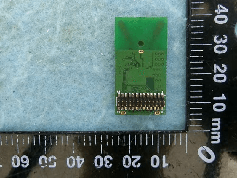
BV2-EW21DM
Jul 06, 2020DENON Wireless Module 5G
Equipment Class
NII - Unlicensed National Information Infrastructure TX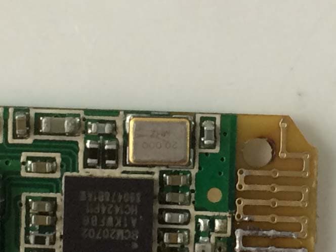
BV2H1GPDONGLE
Apr 01, 2015Bluetooth Dongle
Equipment Class
JBP - Part 15 Class B Computing Device Peripheral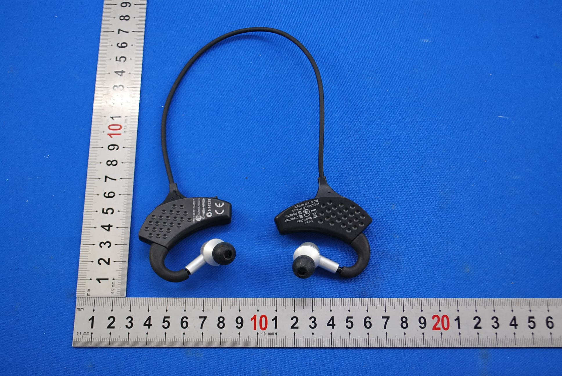
BV2-AH-W200EM
Sep 04, 2013Bluetooth Headphones
Equipment Class
DSS - Part 15 Spread Spectrum Transmitter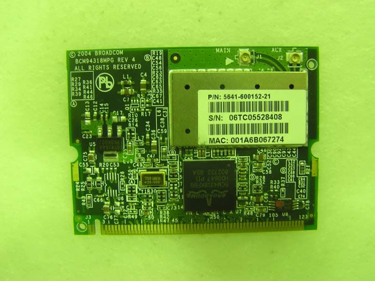
BV2-MPGBR052
May 14, 2007WIRELESS LAN MINI PCI ADAPTER
Equipment Class
DTS - Digital Transmission System