BVCAMB4315.247 WIRELESS LR-WPAN IN 2.4 GHz BAND USING DIGITAL SS.
Tyco Safety Products/Sensormatic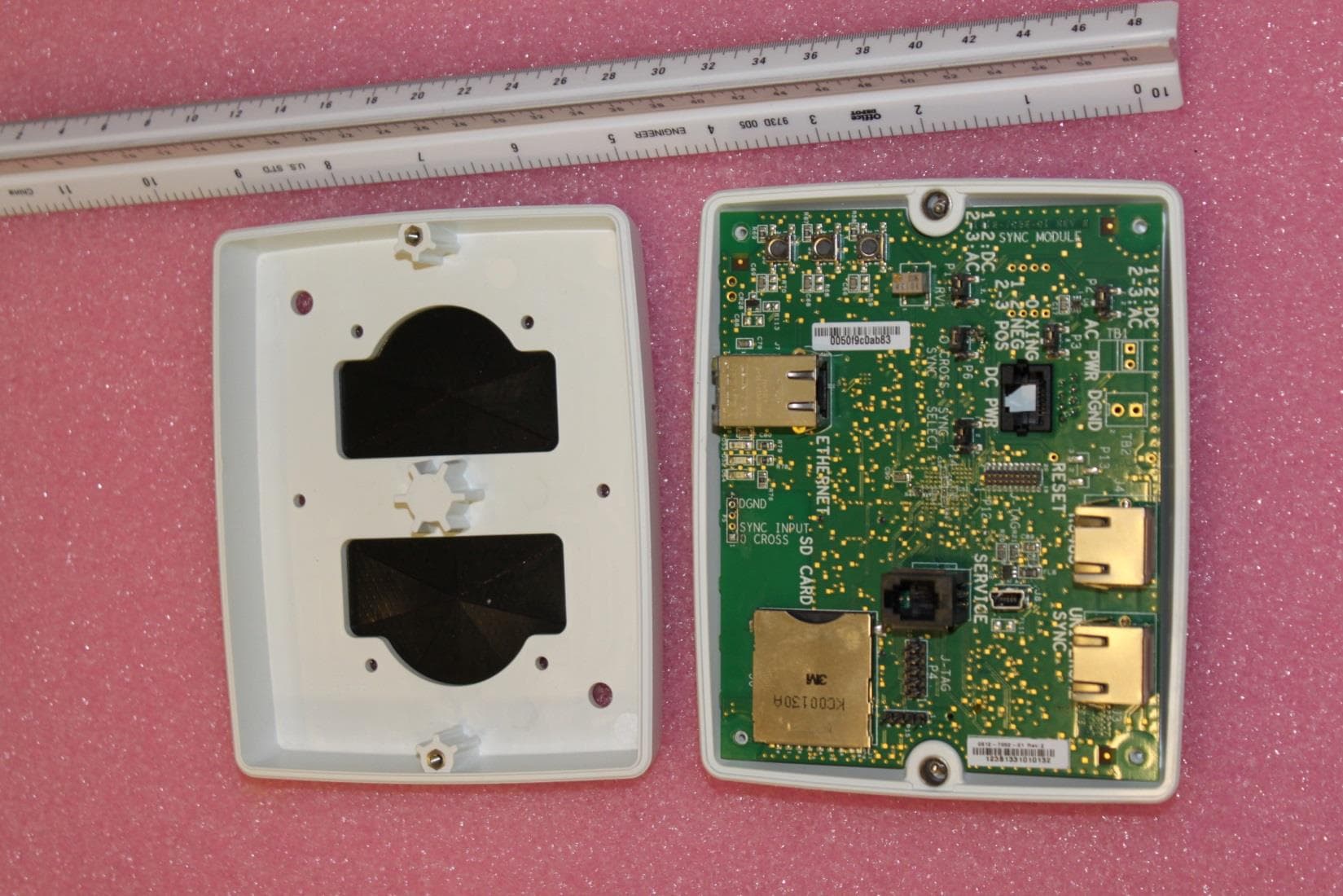
Click to zoom
Application Details
- Equipment Class
- DTS - Digital Transmission System
- Date of Grant
- Jan 06, 2014
- Application Purpose
- Original Equipment
- Date of Application
- Jan 06, 2014
- Equipment Note
- 15.247 WIRELESS LR-WPAN IN 2.4 GHz BAND USING DIGITAL SS.
- Frequency Range
- 2402.00000000 - 2481.50000000
- Country
- United States
Documents & Files
Document Text
Text extracted from the exhibit documents filed with the FCC. Open a document above to read the original.
Users Manual
ZBAMB4300 SYNC ACCESS POINT 8200-0958-03, REV. 2B INSTALLATION GUIDE 1 of 7 ZBAMB4300 Sync Access Point Installation Guide for Lowe’s ® Hardware Stores The ZBAMB4300 Sync Access Point (Sync AP) is an AC line zero-crossing detector that can transmit zero crossing data to nearby ZBAMB2070 Mobile Handheld Deactivators to prevent detection interference with nearby EAS detectors. This guide explains only how to install the Sync AP in a Lowe’s hardware store. For setup instructions, see ZBAMB4300 Sync AP Connection and Setup Guide 8200-0958-06. If you need assistance... Contact your Sales Representative. © 2013 Sensormatic Electronics, LLC ZBAMB4300 SYNC ACCESS POINT 8200-0958-03, REV. 2B INSTALLATION GUIDE 2 of 7 Installation Locations On the wall near the main or lumber entrance In the Universal Outdoor Enclosure near the garden center entrance. OR ZBAMB4300 SYNC ACCESS POINT 8200-0958-03, REV. 2B INSTALLATION GUIDE 3 of 7 Safety WARNING: Install the AP in an air space not used for environmental air. DO NOT install it in a plenum or other environmental air-handling space. Cables placed in environmental airspace must be plenum rated unless the cables are in raceways. All wiring must be through conduit. Ensure that all safety instructions within this manual are continuously observed and respected during the installation and/or operation of this device. Mount the AP only as shown in this guide. Mounting the module any other way may affect its operation. The manufacturer is not responsible for any radio or TV interference caused by unauthorized modifications to this equipment. Such modifications could void the user’s authority to operate the equipment. The antennas used for this transmitter must be installed to provide a separation distance of at least 20cm (8in) from all persons and must not be collocated or operating in conjunction with any other antenna or transmitter. Parts Required Supplied Part Qty. Part Number Power Supply Module* 1 5606-0079-01 Install Kit (indoor install only) 1 0352-0580-01 Connector, Female, RJ45 1 2109-0717-01 Cable, Cat5, 4.6m (15ft) 1 6003-0266-02 Coupler, Female-to-Female, Cat5 1 2109-0906-01 * Includes power cord 0352-0547-xx. Not Supplied (Order Separately) Part Qty. Part Number Install Kit (for outdoor enclosure) 1 0352-0591-01 Bracket, Mounting 1 0505-1544-01 Bracket, Corner/Wall Mount 1 0500-7844-01 Screw, Self-Tapping, PHP, #6x34in 4 2816-7634-32 Screw, Tapcon, HXWH, 3/16x3/4in 4 2816-7683-02 Drill Bit, Tapcon, 5/32x3-1/2in 1 2816-7683-10 Anchor, HLW Wall, ¼-20, 1/8-5/8 4 2880-0025-02 Screw, Mach, M3x8, PHP (not used) 1 5801-1051-120 Screw, Self-Tapping, 8x32, PHP 4 5810-5091-120 Nut, Locking, M3 (not used) 2 5826-0200-020 Nut, Locking, M4 4 5826-0300-020 Purchase Part Qty. 3/4-inch Conduit, Preferred (as required) – 4x4 Electrical Box, Deep 1 ZBAMB4300 SYNC ACCESS POINT 8200-0958-03, REV. 2B INSTALLATION GUIDE 4 of 7 Installation A: Main/Lumber Entrance For the garden center entrance, see Installation B. Electrical Connection Points The electrical connections near the EAS system are generally the same, but may vary from store to store. A typical scenario is described below. Power Cable Route The power cable route goes from: The AC outlet inside the main electrical box in which the power supply module (1) and female- to-female coupler (2) reside. Down through existing conduit into the UltraLink enclosure below. Up through existing conduit and alarm module electrical box (3). To a 4x4 electrical box (4) mounted 3.7m (12ft) from the floor (the Sync AP mounts here using two screws as shown below). A length of conduit (5) will need to be added for power to reach this box. Notes: The 4.6m (15ft) Cat5 cable supplied is used to get power to the Sync AP. DO NOT connect this cable to the Sync AP or the female-to-female coupler inside the main electrical box at this time. These connections will be done at the end of the setup process. If the cable does not fit through the conduit, then cut off one of its connectors close to the end of the cable, route the cable, then reattach the connector (see page 5 for reattachment instructions). 3.7M (12FT) FROM FLOOR Main Electrical Box UltraLink Enclosure Alarm Module 1 2 3 4 5 Do not connect. Leave the cable hanging inside the Sync AP ZBAMB4300 SYNC ACCESS POINT 8200-0958-03, REV. 2B INSTALLATION GUIDE 5 of 7 Installation B: Garden Center Entrance For the main/lumber entrance, see Installation A. Electrical Connection Points The location of electrical connection points near the EAS system is generally the same for each store, but details may vary from store to store. These instructions cover a typical scenario. Sync AP Mounting Location Mount the Sync AP in the Universal Outdoor Enclosure. If the enclosure has a drop-down floor-max fiberglass panel: Drill an access hole in the fiberglass for the cable and mount the Sync AP where shown. Plug the power supply into the AC outlet in the enclosure and route its cable up through the drop-down panel and through the access hole. DO NOT connect the cable to the Sync AP. This will be done during the setup process. If the enclosure DOES NOT have a drop- down floor-max fiberglass panel: Mount the Sync AP in the interior upper-left corner of the enclosure using optional mounting bracket 0505-1544-01* and four screws. Plug the power supply into the AC outlet in the enclosure and route its cable up behind the bracket. Attach the Sync AP to the bracket using two screws and connect the cable to the Sync AP. DO NOT connect the cable to the Sync AP. This will be done during the setup process. * Order Sync AP Mounting Bracket Install Kit 0352- 0591-01. - OR - RJ45 Pin Assignments Male plug pin assignments are according to the T-568B standard. All connections are “straight through” from plug to plug, that is: pin 1 to pin 1, pin 2 to pin 2, and so on Pin Wire Color 1 Orange/White 2 Orange 3 Green/White 4 Blue 5 Blue/White 6 Green 7 Brown/White 8 Brown Pin 1 ZBAMB4300 SYNC …
Text truncated - open the document above for the full version.
Cover Letter(s)
Nov. 18, 2013 Timco Engineering, Inc. 849 N.W. State Road 45 P.O. Box 370 Newberry, Florida 32669 USA Re: Application for a Confidential Request for DSS wireless network Device, FCC ID: BVCAMB43 Dear Sir or Madam: Federal Communications Commission Authorization and Evaluation Division Confidentiality Request regarding application for certification. Pursuant to Sections 0.457 and 0.459 of the Commission’s Rules, we hereby request confidential treatment of information accompanying this application as outlined below: BVCAMB43 Conf OpDes.pdf BVCAMB43 Conf Schem.pdf BVCAMB43 Conf BlkDia.pdf The above materials contain trade secrets and proprietary information not customarily released to the public. The public disclosure of these materials may be harmful to the applicant and provide unjustified benefits to its competitors. The applicant understands that pursuant to Section 0.457 of the Rules, disclosure of this application and all accompanying documentation will not be made before the date of the Grant for this application. Sincerely, William D. Owsley Principal EMC Engineer Compliance Engineering Tyco Retail Solutions Sensormatic Electronics, LLC. 6600 Congress Ave. Boca Raton, FL. 33487
Cover Letter(s)
FCC ID: BVCAMB43 IC: 3506A-AMB43 Nov. 22, 2013 Timco Engineering, Inc. 849 N.W. State Road 45 P.O. Box 370 Newberry, Florida 32669 USA Re: Application for a Limited Single Modular Request for wireless private network transceiver device, FCC ID: BVCAMB43 IC: 3506A-AMB43 Dear Sir or Madam: Pursuant to Section 15.212 (b) of the FCC Rules and IC RSS-Gen I 3 2010 Sections 3.2.2 and 3.2.3; “(b) A limited modular approval may be granted for single or split modular transmitters that do not comply with all of the above requirements, e.g. , shielding, minimum signaling amplitude, buffered modulation/data inputs, or power supply regulation, if the manufacturer can demonstrate by alternative means in the application for equipment authorization that the modular transmitter meets all the applicable part 15 requirements under the operating conditions in which the transmitter will be used. Limited modular approval also may be granted in those instances where compliance with RF exposure rules is demonstrated only for particular product configurations. The applicant for certification must state how control of the end product into which the module will be installed will be maintained such that full compliance of the end product is always ensured.” This device generates a series of DSS pulses per 15.247 in the 2400-2483.5 MHz band and is used as a private wireless network to synchronize a number of EAS anti-pilferage devices. The radio module is a small pcb card the mates to a larger digital motherboard for power and data. These are built and assembled and installed under the applicants’ direct control. The transmitter complies with the modular requirements. The transmitter radio elements are not shielded. The modulation/data input is buffered. The radio has its own regulated power supply. The antenna is built into the pcb as a permanent feature.. The radio was tested installed on the motherboard. There is a permanently affixed label/print with FCC ID number. The transmitter does not comply with all the modular requirements. It is not available to be installed into any other systems or devices outside of the applicants’ control. Testing and results indicated in the test report, demonstrate that the transmitter meets the general radiated limits of 15.209 and also the conducted limits of 15.207 and complies with 15.247 for DSS transceivers. Therefore, as we the applicant will always maintain control of the end product by manufacturing the transmitter board into a variety of chassis, all to perform the same function of a private wireless network, we are applying for a Limited Modular approval. Sincerely, William D. Owsley Principal EMC Engineer Sensormatic Electronics, LLC. 6600 Congress Ave. Boca Raton, FL. 33487
Cover Letter(s)
FCC ID: BVCAMB43 IC: 3506A-AMB43 FCC Declaration of Conformity Statement Model: AMB4310 FCC ID: BVCAMB43 This equipment complies with the limits for a Class B digital device, pursuant to Part 15 of the FCC rules. These limits provide reasonable protection against harmful interference in a commercial or residential installation. This equipment can radiate radio frequency energy and, if not installed and used in accordance with the instructions, may cause harmful interference. If this equipment does cause harmful interference to radio or television reception, which can be determined by turning the equipment off and on, the user is encouraged to correct the interference by one or more of the following: reorient or relocate the receiving antenna, increase the separation between the equipment and receiver, connect the equipment on a circuit different from that to which the receiver is connected, consult the dealer or an experienced radio/TV technician for help. Equipment changes or modifications not expressly approved by Sensormatic Electronics, LLC, the party responsible for FCC compliance, could void the user’s authority to operate the equipment and could create a hazardous condition. Industry Canada (IC) IC: 3506A-AMB43 This device complies with Industry Canada licence-exempt RSS standard(s). Operation is subject to the following two conditions: (1) this device may not cause interference, and (2) this device must accept any interference, including interference that may cause undesired operation of the device. Le présent appareil est conforme aux CNR d’Industrie Canada applicables aux appareils radio exempts de licence. L’exploitation est autorisée aux deux conditions suivantes : (1) l’appareil ne doit pas produire de brouillage, et (2) l’utilisateur de l’appareil doit accepter tout brouillage radioélectrique subi, même si le brouillage est susceptible d’en compromettre le fonctionnement. This Class B digital device complies with Canadian ICES-003. Cet appareil numérique de la classe B est conforme à la norme NMB-003 du Canada. Sincerely, William D. Owsley / Principal EMC Engineer Tyco Safety Products / Sensormatic Electronics, LLC. 6600 Congress Ave. Boca Raton, FL. 33487
External Photos
FCC ID: BVCAMB43 IC: 3506A-AMB43 External photos Back side. FCC label placed along short edge. FCC ID: BVCAMB43 IC: 3506A-AMB43 Front side FCC ID: BVCAMB43 IC: 3506A-AMB43 Open case. RF board is mounted to other side of digital board.
ID Label/Location Info
FCC ID: BVCAMB43 IC: 3506A-AMB43 FCC label location External photos Back side. FCC label placed along short edge. FCC ID: BVCAMB43 IC: 3506A-AMB43 RF board top side with temporary RF output connector and cable for testing, and larger digital board. Arrow points to FCC ID to be printed on this surface along the edge.
ID Label/Location Info
FCC ID: BVCAMB43 IC: 3506A-AMB43 FCC Internal label Label to be printed in silk screen on board. FCC ID: BVCAMB43 IC: 3506A-AMB43
Internal Photos
FCC ID: BVCAMB43 IC: 3506A-AMB43 Internal photos Digital board and RF board assembled FCC ID: BVCAMB43 IC: 3506A-AMB43 Digital board backside FCC ID: BVCAMB43 IC: 3506A-AMB43 RF board top with temporary RF output connector and cable for testing, and larger digital board. Arrow points to FCC ID to be printed on this surface along the edge. FCC ID: BVCAMB43 IC: 3506A-AMB43 RF board backside with larger digital board and test cable. FCC ID: BVCAMB43 IC: 3506A-AMB43 FCC ID: BVCAMB43 IC: 3506A-AMB43
Test Report
FCC ID: BVCAMB43 IC: 3506A-AMB43 Page 1 of 44 TYCO SAFETY PRODUCTS SENSORMATIC ELECTRONICS, LLC. EMC TEST REPORT Model: AMB-4300 Wireless Access Point FCC ID: BVCAMB43 IC: 3506A-AMB43 Intentional Radiator 15.247 (DSSS 2400 – 2483.5 MHz) FCC 47 CFR, Part 15, Subpart B, and Subpart C Industry Canada ICES-003e, RSS GENe, RSS-210e EMC Engineer 6600 Congress Ave. Boca Raton, FL. 33487 USA Revision Level Date Reason Rev. A Nov. 22, 2013 Initial FCC ID: BVCAMB43 IC: 3506A-AMB43 Page 2 of 44 1 SUMMARY OF RESULTS ........................................................................................................................... 3 2 GENERAL ...................................................................................................................................................... 5 2.1 Test Site Registration ............................................................................................................................... 5 2.2 Test Procedures ........................................................................................................................................ 5 2.3 Sample Calculation – Radiated & Conducted Emissions ........................................................................ 6 2.4 Uncertainty of Measurements .................................................................................................................. 8 3 DESCRIPTION AND CHARACTERISTICS OF THE EUT ........................................................................ 9 3.1 Model / Type Designation ........................................................................................................................ 9 3.1.2 Overview ........................................................................................................................................... 9 3.1.3 Environment ...................................................................................................................................... 9 3.1.4 Frequency Characteristics and Internal Clocks ................................................................................. 9 3.2 TEST SET-UP BLOCK DIAGRAM ..................................................................................................... 10 3.2.1 List Of Ports .................................................................................................................................... 10 3.2.2 Accessory Equipment Used During Testing ................................................................................... 11 4 FCC TESTS .................................................................................................................................................. 12 4.1 AC Conducted Emissions, FCC Part 15, Clause 15.107 And 15.207 .................................................... 12 4.2 Radiated Emissions, FCC Part 15, Clause 15.109 and 15.209 (above 30 MHz) ................................... 15 4.3 Conducted RF measurements connection losses and setup. .................................................................. 21 4.4 6 dB Emission Bandwidth. 15.247 (a)(2) ............................................................................................... 22 4.5 Max Conducted Power Output, 15.247 (b)(3)........................................................................................ 23 4.6 Spurious RF Conducted Emissions, 15.247 (d) ..................................................................................... 25 4.7 Maximum power spectral density level in the fundamental emission. 15.247 (e) ................................. 32 4.8 20 dBc Bandwidth from highest level .................................................................................................... 33 4.9 Input Voltage Variation, 15.31(e). ......................................................................................................... 34 4.10 RF Exposure Compliance Requirements per 15.247 (b) (5), 2.1093 (d)(1) Portable ......................... 35 5 EQUIPMENT LIST ...................................................................................................................................... 36 6 ANTENNA FACTORS. ............................................................................................................................... 37 FCC ID: BVCAMB43 IC: 3506A-AMB43 Page 3 of 44 1 SUMMARY OF RESULTS FCC 47 CFR Part 15. Test Requirement Test Limit Comments 15.15 (b) User Accessible Controls Cannot change output power above limit. The product contains no user accessible controls that increase transmission power above permitted levels. 15.31 (e) Vary Input AC Mains Power Does not increase the output power above the limit. Complies. 13.33 (a) Frequency range of radiated measurements General Limits of 15.209, 150 kHz to 24 GHz. E-field measurements comply 15.107 AC Conducted Emissions Unintentional digital emissions subject to Class B limits of 15.107 Digital emissions determined by turning transmitter off. Complies. 15.109 Radiated Emissions Requirements Unintentional digital emissions subject to Class B limits of 15.109 Digital emissions determined by turning transmitter off. Complies. 15.203 Antenna Connector Permanently attached or unique coupling. The antenna is permanently attached. Inverted F. Complies. 15.204(b)(c) System and Antennas Marketed as a system with authorized antenna types Integral internal antenna. Complies. 15.207 (a) (b) AC Conducted Emissions General Limits. Conducted emissions on AC side of DC supply. Complies. 15.205 (a) (b) 15.209 (a) (c) Radiated Emission Comply with limits in 15.209 (a). No intentional emissions in the restricted bands of 15.205 The radiated emissions comply with the general emission limits. Complies. 15.247 (a) (2) Carrier Frequency Separation DTS, 6 dB BW >500 kHz Complies. 15.247 (b) (3) Output Power Maximum 1 W (30 dBm) The EUT complies with the requirement. Max = 7 dBm. Complies. 15.247 (b) (4) Maximum Antenna Gain If gain of transmitting anten…
Text truncated - open the document above for the full version.
Test Setup Photos
FCC ID: BVCAMB43 IC: 3506A-AMB43 Test Setup photos Conducted Emissions FCC ID: BVCAMB43 IC: 3506A-AMB43 Radiated emissions on OATS FCC ID: BVCAMB43 IC: 3506A-AMB43 FCC ID: BVCAMB43 IC: 3506A-AMB43 FCC ID: BVCAMB43 IC: 3506A-AMB43 Radio testing
Contact Information
Applicant
Mark D. Alexis(Manager Regulatory Compliance)
Test Firm
SensormaticWilliam Owsley
[email protected]5619126462
Technical Specifications
| # | Rule Parts | Frequency Range | Power Output |
|---|---|---|---|
| 1 | 15C | 2.40 GHz - 2.48 GHz | 10.00 mW |
Other Applications from Tyco Safety Products/Sensormatic

BVCIDX5000
Jun 23, 2026UHF RFID Reader
Equipment Class
DSS - Part 15 Spread Spectrum TransmitterBVCAMS1137H
Dec 22, 2025Anti Theft System - Electronic Asset Security
Equipment Class
FAP - Part 15 Anti-Pilferage DeviceBVCAMB9012
Sep 10, 2024Label Deactivator Controller
Equipment Class
DCD - Part 15 Low Power Transmitter Below 1705 kHz
BVC-4000-PI26
Sep 24, 2015RM2L-4000-P126, RM2-4000-P126
Equipment Class
DXX - Part 15 Low Power Communication Device Transmitter
BVCAMS90604
May 20, 2014Anti-pilferage Device
Equipment Class
FAP - Part 15 Anti-Pilferage Device