BVCAMB9010ANTI-PILFERAGE DEVICE
Tyco Safety Products/Sensormatic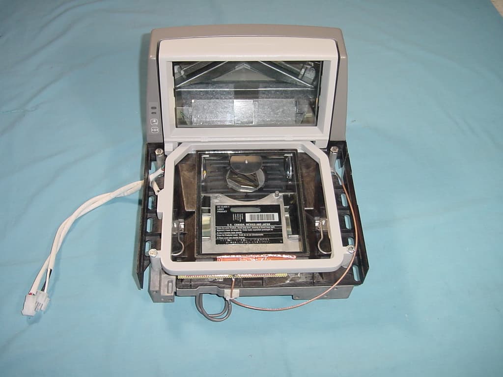
Click to zoom
Application Details
- Equipment Class
- FAP - Part 15 Anti-Pilferage Device
- Date of Grant
- Aug 08, 2007
- Application Purpose
- Original Equipment
- Date of Application
- Aug 06, 2007
- Equipment Note
- ANTI-PILFERAGE DEVICE
- Frequency Range
- 0.05750000 - 0.06000000
- Country
- United States
Documents & Files
Document Text
Text extracted from the exhibit documents filed with the FCC. Open a document above to read the original.
Users Manual
ZBAMB9010 BI-PLANAR ANTENNA CONTROLLER 8200-0747-01, REV. 4A INSTALLATION AND SERVICE GUIDE 1 of 14 1ZBAMB9010 Bi-Planar Antenna Controller Installation and Service Guide Contents About this Guide....................................................1 About the Product..................................................2 Product Limitations................................................4 Device Interaction ...........................................4 Deactivator Performance ................................4 Antennas.........................................................4 Installation .............................................................4 Hardware Setup ..............................................4 Software Setup ...............................................5 Service Configurator Control Definitions ...............7 Troubleshooting...................................................11 Basic Troubleshooting ..................................11 Advanced Troubleshooting ...........................12 Specifications ......................................................13 Connector Inputs/Outputs ...................................13 Declarations ........................................................14 © 2007 Sensormatic Electronics About this Guide This guide explains how to install, setup, and troubleshoot the AMB-9010 controller. It does not explain how to mount the controller and its associated antenna into a counter or scanner. Mounting instructions are supplied with the mounting bracket and antenna. Note: Because customer requirements dictate the location of components at the customer site, your ADT representative will supply this information separately. If you need assistanceÖ Customers: 1-800-241-6678 (Sensormatic/ADT Customer Response Center) ADT Technicians (North America): Sensormatic Technical Support 1-800-543-9740 Direct: 561-939-3290 Hours: 8 a.m. to 6 p.m. EST Email: [email protected] ADT Technicians (Europe): TFS EMEA +800 CALLTYCO (+800.22.55.89.26) UK only: +44 (0) 8701.238.787 France only: +33 (0) 4.72.79.14.83 Spain only: +900.10.19.45 Direct: +31 475.352.722 Fax: +31 475.352.725 Hours: 8 a.m. to 6 p.m. CET Email: TFSEMEA.Support @ tycoint.com www.tycosafetyproducts-europe.com For all training inquires: Email: [email protected] External Power Supply Controller ZBAMB9010 BI-PLANAR ANTENNA CONTROLLER 8200-0747-01, REV. 4A INSTALLATION AND SERVICE GUIDE 2 of 14 About the Product The AMB-9010 controller connects to an AMB- 5182 low inductance antenna to detect and deactivate security labels. Antennas used with the controller: Note: An EEPROM in the antenna cable automatically adjusts the controller to the antennaís characteristics. If the EEPROM is not programmed, the antenna type settings default to PowerPad Pro. Low Inductance Antennas Deactivation Height Antenna* Tx Power Full Power MMS Power AMB-5182 (ZBAMB5182) Normal 20ñ22.5cm (8ñ9in) N/A Internal features: • External power supply with a universal ac input and 22Vdc output and line sync signal to the controller. • Automatic antenna type detection, except if using an optional antenna cable extension. • Auto and re-synchronization • Adjustments to transmit and deactivation fields to correct for counter thickness • Remote key switch detection • Status LED for power on, communication activity, and basic diagnostics. • Label type (SR/DR) and power level (full or MMS). • Advanced settings. • Diagnostics. Front panel features: a. Power: External ac-dc power supply connects here. b. RS-485 (Network) port: This 6-position modular jack provides RS-485 communication between Sensormatic devices and a POS system. An RS-485 based Remote provides AcoustoLink and FootLink functionality on this port. c. Status LED: For indication of power on/antenna connected (green), antenna disconnected (off), deactivation disabled (green blinking), deactivation (orange blinking), and non-recoverable fault (red). d. SERVICE port: This 4-position modular jack provides RS-232 communication to a laptop computer for advanced setup and diagnostics. e. SCANNER port: This 8-position modular jack allows a POS system, such as a bar code scanner, to control deactivation and also provides RS-232 communication if required. These ports accept various control voltages (see specs on page 13). f. REMOTE port: This 6-position RJ-11 modular jack supports the legacy Sensormatic remote alarm module. Deactivation can be disabled on this port. g. ANTENNA port: Receives a cable from the antenna. a b c d e f g ZBAMB9010 BI-PLANAR ANTENNA CONTROLLER 8200-0747-01, REV. 4A INSTALLATION AND SERVICE GUIDE 3 of 14 Power Cord Power cord length is 183cm (6ft). The cord attach- es the external power supply to an ac outlet. The type of cord used depends on the country of use. Setup A software configurator is used to setup the controller. The configurator: • Installs on a laptop computer that plugs into the SERVICE port. • Requires Windows Æ 2000 or XP operating system software on the laptop. Auto Synchronization Enabled using the software configurator, auto synchronization: • Upon power up, automatically synchronizes the controller to the strongest signal picked up by an antenna. • Enables the controller to sync its transmission to other nearby EAS systems to prevent their interference during tag detection. • The Universal Sync standard (wired sync) is supported on the NETWORK port as either transmit or receive mode, and is set up in the software configurator. • If Sensormatic devices using wireless sync are nearby, an RS-485 based Smart Remote that plugs into the NETWORK port on the controller can be used to achieve synchronization. POS Integration POS devices such as bar code scanners can control deactivation when connected to the SCANNER port. • POS devices must be programmed with special software. • Voltage specifications are on page 13. Networking A Sensormatic peripheral device such as an EAS detection system can send data to a storeís POS network usin…
Text truncated - open the document above for the full version.
Cover Letter(s)
June 20, 2007 Timco Engineering, Inc. 849 N.W. State Road 45 P.O. Box 370 Newberry, Florida 32669 USA Re: Request for withholding from public disclosure proprietary information submitted pursuant to an application for certification for a low power transmitter. FCC ID: BVCAMB9010 Dear Sir or Madam: Sensormatic Electronics Corporation requests certain materials submitted with this application for certification of device FCC ID: BVCAMB9010 be withheld from public disclosure. This request is made under the provision of FCC DA 04-1705 dated 6/15/04, 47 CFR 0.457 (d), 0.459, and 5 USC 552(b)(4) Freedom of Information Act, Trade Secrets. The items for which confidentiality is requested include the Operational Description, Block Diagram and Schematic Diagrams. This information contains proprietary information (trade secrets) regarding the circuit operation and capabilities (specific values of components, circuit design details and system architecture) which are the result of our extensive investment in research and development. Without the disclosed information, competitive organizations would take considerable more time to assess and develop a workable competitive product. As a result, we believe that disclosure of these company-guarded materials would compromise our leading position in this market. We therefore formally request that the materials identified “Confidential” be kept strictly confidential and not made available for inspections by any other party, except on a need to know basis for the sole purpose of the certification process. Sincerely, William D. Owsley Principal Engineer, Compliance Engineering
External Photos
AMB 5182 Coil antenna Installed in Scanner Covers removed from scanner Coils of antenna
External Photos
AMB 5278 coil antenna photos In scanner Scanner covers removed Coils of antenna
ID Label/Location Info
2402-1296-24 ® FCC ID: BVCAMB9010 This device complies with part 15 of the FCC rules. Operation is subject to the following two conditions: (1) This device may not cause harmful interference, and (2)This device must accept any interference received, including interference that may cause undesired operation. This Class A digital apparatus complies with Canadian ICES-003. Cet appareil numérique de la classe A est confrome á la norme NMB-003 du Canada. IC: 3506A-AMB9010 ASSEMBLED IN PUERTO RICO-0105 TYPE: AMB-9010 MFD: 05-07 P/N: 0101-0194-01 REV: A SERIAL NO: ccctyyww123456 RATING: 100-240V~ 50/60Hz 2.5A Max. NRTL BARCODE N205
ID Label/Location Info
Regulatory Label location (bottom, front )
Internal Photos
AMB 9010 photos
Test Report
W:\T\TycoSafetyProducts_BVC\2372UC7\AMB-9010 Controller Test Report_11-30-06 FCC-IC.doc Page 1 of 18 TYCO SAFETY PRODUCTS SENSORMATIC EMC TEST PLAN and REPORT Model: AMB9010 Controller Standards Tested 47 CFR, Part 15 RSS 210 W:\T\TycoSafetyProducts_BVC\2372UC7\AMB-9010 Controller Test Report_11-30-06 FCC-IC.doc Page 2 of 18 1 DESCRIPTION AND CHARACTERISTICS OF EQUIPMENT UNDER TEST (EUT). 3 1.1 CONSTRUCTION OF EQUIPMENT 4 1.1.1 Block Diagram of System to be Tested 5 1.2 LIST OF PORTS 6 1.3 EUT Characteristics 7 1.3.1 FREQUENCY CHARACTERISTICS 7 1.3.2 FREQUENCY(S) 7 1.4 TRANSMITTER RF CARRIER CHARACTERISTICS 8 1.4.1 MAXIMUM RATED TRANSMITTER OUTPUT 8 1.5 OTHER EQUIPMENT CHARACTERISTICS 9 2 SUMMARY OF APPLICABLE TESTS 10 2.1 North American Transmitter Type Tests 10 2.2 TESTS PER 47 CFR Part 15 and EN 55022 11 2.2.1 CONDUCTED EMISSIONS – Mains Port; CLAUSE 15.107 and 15.207 11 2.2.2 RADIATED EMISSIONS, E-Field, CLAUSE 15.109 and 15.209 12 2.2.3 RADIATED EMISSIONS, E-Field (Class A), EN 55022, Table 4. 13 2.2.4 RADIATED EMISSIONS, H-Field , CLAUSE 15.209 14 2.3 TESTS PER RSS 210 15 2.3.1 MODULATION BANDWIDTH, RSS 210, Clause 5.9.1 15 3 EQUIPMENT LIST 17 W:\T\TycoSafetyProducts_BVC\2372UC7\AMB-9010 Controller Test Report_11-30-06 FCC-IC.doc Page 3 of 18 1 Description and Characteristics of Equipment Under Test (EUT). TYPE DESIGNATION (See Note 1) The type designation may be either a single alphanumeric code or an alphanumeric/code divided into two parts. TYPE DESIGNATION AS A SINGLE ALPHANUMERIC CODE: | A | M | B | 9 | 0 | 1 | 0 | | | | | | | | | | OR TYPE DESIGNATION IN TWO PARTS: 1. EQUIPMENT SERIES No. (See Note 2) | | | | | | | | | | | | | | | | | | 2. EQUIPMENT SPECIFIC No. (See Note 3) | | | | | | | | | | | | | | | | | | Note 1: This is the manufacturer’s numeric or alphanumeric code or name that is specific to a particular equipment. It may contain information in coded form on the characteristics of the equipment e.g. frequency, power. The manufacturer is free to choose the form of the type designation. Note 2: This is the number, code or trade name used by the manufacturer to describe a series or “family” of equipment of substantially the same mechanical and electrical construction which will include a number of related equipments. This number is often referred to as the “model no.” Note 3: This is the manufacturer’s identification number given to a specific equipment in the series or “family” of equipments. It is often referred to as the “identification number”. W:\T\TycoSafetyProducts_BVC\2372UC7\AMB-9010 Controller Test Report_11-30-06 FCC-IC.doc Page 4 of 18 1.1 CONSTRUCTION OF EQUIPMENT [ ] Single unit (See Note 4) [ X ] Multiple units If multiple units describe each one clearly: Unit Product Code Part Number Controller AMB9010 Antenna/s AMB5182, AMB5278 AC-DC Converter Various suppliers Note 4: “UNIT” means a physically separate item of the equipment. The equipment under test may consist of two separate units. In this case additional sheets covering the transmitter and receiver characteristics for both units would be required, if unit 1 and unit 2 are covered by the same TYPE DESIGNATION. 1.1.1 Block Diagram of System to be Tested Ault AC-DC Converter AMB9010 Controller 5278 Ant coil or 5182 Ant coil C Laptop Configurator F RS232 Smart Alarm D RS485 E On/Off Switch G PSC 8200 Scanner Or NCR B A H W:\T\TycoSafetyProducts_BVC\2372UC7\AMB-9010 Controller Test Report_11-30-06 FCC-IC.doc Page 5 of 18 W:\T\TycoSafetyProducts_BVC\2372UC7\AMB-9010 Controller Test Report_11-30-06 FCC-IC.doc Page 6 of 18 1.2 LIST OF PORTS Ident Function * Classif. ** Max Cable Length Test Length Cable Type A AC Mains ac power > 1m but ≤ 3 m 1.83m; .3m 3 conductor unshielded B Power Supply Secondary dc power > 1m but ≤ 3 m 2.1m 2 conductor unshielded C Ant Cable 1 signal/contro l < 3 m 1.5m 3 conductor Shielded D RS485 Network signal/contro l < 3 m 2.1m 4 conductor unshielded E RS 485 Network signal/contro l >3 m 2.1m 4 conductor unshielded F RS232 signal/contro l >3 m 10m 4 conductor unshielded G RJ45 signal/contro l >3 m 2.5m 8 conductor unshielded * Classify ports as ac power, dc power, or signal/control. ** Classify maximum cable lengths as ≤ 1 m, > 1m but ≤ 3 m, or > 3m W:\T\TycoSafetyProducts_BVC\2372UC7\AMB-9010 Controller Test Report_11-30-06 FCC-IC.doc Page 7 of 18 1.3 EUT Characteristics 1.3.1 FREQUENCY CHARACTERISTICS Method of frequency generation [ X ] CRYSTAL [ X ] SYNTHESIZER [ ] OTHER: 1.3.2 FREQUENCY(S) 60 MHz 8 MHz 1.84 MHz 1.4 MHz 200 kHz 58 kHz W:\T\TycoSafetyProducts_BVC\2372UC7\AMB-9010 Controller Test Report_11-30-06 FCC-IC.doc Page 8 of 18 1.4 TRANSMITTER RF CARRIER CHARACTERISTICS 1.4.1 MAXIMUM RATED TRANSMITTER OUTPUT -22.5 dB uV/m Field strength at 10 m Is transmitter intended for: Intermittent duty only [X] Yes [ ] No Transmitter ON 1.6ms seconds/minutes Transmitter Period 5.55 / 11.11 / 16.67 / 22.22 ms seconds/minutes AVERAGE DUTY CYCLE 14.4% Is transmitter carrier output variable [ ] Yes [ x ] No RF output Maximum Minimum (Volts; provides max current relationship) Is the RF output continuously variable [ ] Yes [ X ] No or stepped [ ] Yes [ X ] No EQUIPMENT RATINGS Mains frequency : 50 - 60 Hz Temperature range : 0 - 50 °C Humidity range : 0 - 90 % non-condensing W:\T\TycoSafetyProducts_BVC\2372UC7\AMB-9010 Controller Test Report_11-30-06 FCC-IC.doc Page 9 of 18 1.5 OTHER EQUIPMENT CHARACTERISTICS INFORMATION TO DETERMINE PERFORMANCE ASSESSMENT PRIMARY FUNCTIONS TO BE TESTED DURING AND AFTER EMC TESTS The primary function to be tested is anti-theft label detection and deactivation. ANCILLARY EQUIPMENT USED DURING TESTING Hard tag Lap Top Remote Switch Smart Alarm POS Scanner USER CONTROL FUNCTIONS: None. STORED DATA: none. METHODS USED TO ACCESS NORMAL OPERATION: Power up system with no tags in the field. When the “ready” LED is properly illuminated, place a hard tag on the transmitter/deactivator pad. With these conditions, The LAPTOP connected to the service port via RS232 c…
Text truncated - open the document above for the full version.
Test Report
AMB-9010 FCC Information June 14, 2007 Transmitter measurements at antenna connector P1, Pin 1 to chassis Typical transmitter bursts are for 1.6mS and at intervals of 5.55mS, 11.11mS, 16.67mS, or 22.22mS on the 60Hz ac line or 6.67mS, 13.33mS, 20mS, or 26.67 for a 50Hz ac line. This Tx voltage waveform shows the 22.22mS burst interval. The cursors in the next waveform show that the Tx bursts are less than 166V peak to peak on the antenna connector, and provides more detail of a single Tx burst. The Tx burst contains swept frequencies in 7 discrete steps from 57.5kHz to 60kHz. Transmitter currents, Channel 1 (X), through antenna connector P1-1 to P1-3 The above waveform is the Tx current in a low inductance antenna (70uH) at the normal transmit power level. It is less than 2A peak. This waveform is a single Tx current burst. The next waveform shows both the Tx voltage at P1-1 and the Tx current, as well as their inductive phase relationship. This waveform shows more Tx current detail at the start of the Tx burst.. The waveform below is a single Tx current burst at the boost transmit power level (maximum for the 70uH antenna family). It is less than 3.6A peak. Deactivation Waveforms Deactivation Voltage Waveform at P1-1 to P1-3 (Chassis) The waveform starts at the 535V dc level, and follows the equation: v(t) = 535 * exp(-a*t) * cos((1/2*pi()*sqrt(LC))*t) The waveform voltage glitches are the SCR commutation spikes and do not appear in the current waveform. The current waveform follows the equation: i(t) = (535 / sqrt(L/C)) * exp(-a*t) * sin((1/2*pi()*sqrt(LC))*t) The measured current peak was 600A for the 70uH antenna family. L = 70uH and C = 100uF typical, while a is approximately 1070 Nepers. The frequency f is about 1900Hz. The maximum repetition rate is 3 times per second. Additional detail of the initial deactivation voltage waveform. The ring down typically takes 5 to 7 cycles for the 70 uH antennas and takes 7 to 9 cycles for the 1 mH antennas. 70uH antennas Vinitial = 535V a = 1070 Neper f = 1900Hz L = 70uH C = 100uF 1mH antennas Vinitial = 500V a = 178 Neper f = 480Hz L = 1000uH C = 100uF
Test Setup Photos
W:\T\TycoSafetyProducts_BVC\2372UC7\AMB-9010 Controller Test Report_11-30-06 FCC-IC.doc Page 16 of 18
Contact Information
Applicant
Mark D. Alexis(Manager Regulatory Compliance)
Test Firm
Tyco Safety Products / SensormaticWilliam Owsley
[email protected]561-912-6462
Technical Specifications
| # | Rule Parts | Frequency Range | Power Output |
|---|---|---|---|
| 1 | 15C | 0.0575 MHz - 0.06 MHz | - |
Other Applications from Tyco Safety Products/Sensormatic

BVCIDX5000
Jun 23, 2026UHF RFID Reader
Equipment Class
DSS - Part 15 Spread Spectrum TransmitterBVCAMS1137H
Dec 22, 2025Anti Theft System - Electronic Asset Security
Equipment Class
FAP - Part 15 Anti-Pilferage DeviceBVCAMB9012
Sep 10, 2024Label Deactivator Controller
Equipment Class
DCD - Part 15 Low Power Transmitter Below 1705 kHz
BVC-4000-PI26
Sep 24, 2015RM2L-4000-P126, RM2-4000-P126
Equipment Class
DXX - Part 15 Low Power Communication Device Transmitter
BVCAMS90604
May 20, 2014Anti-pilferage Device
Equipment Class
FAP - Part 15 Anti-Pilferage Device