BVCAMB9020ANTI THEFT AUXILIARY DEVICE
Tyco Safety Products/Sensormatic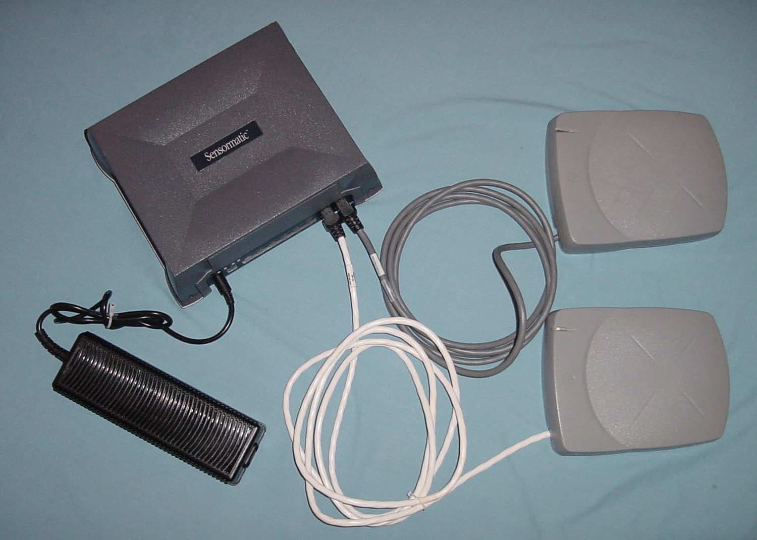
Click to zoom
Application Details
- Equipment Class
- FAP - Part 15 Anti-Pilferage Device
- Date of Grant
- Nov 25, 2003
- Application Purpose
- Original Equipment
- Date of Application
- Nov 25, 2003
- Equipment Note
- ANTI THEFT AUXILIARY DEVICE
- Frequency Range
- 0.05800000 - 0.05800000
- Country
- United States
Documents & Files
Document Text
Text extracted from the exhibit documents filed with the FCC. Open a document above to read the original.
Users Manual
Preliminary 2003-11-21 DUAL ANTENNA SCANMAX PRO DEACTIVATOR CONTROLLER 8200-0365-01, REV. 1A INSTALLATION AND SERVICE GUIDE 1 of 12 AMB-9020 Dual Antenna ScanMax ® Pro Deactivator Controller Installation and Service Guide The Dual Antenna Deactivator controller, along with an antenna, is used to deactivate security labels. Antennas used with the controller are: • PowerPad Pro (ZBSMPPP) • Slim Pad Pro (ZBSMPSP) • CompactPad Pro Tabletop (ZBSMPCP) • CompactPad Pro Flush Mount (ZBSMPCP-F) • HS Pro (ZBSMPHS) • LP Pro (ZBSMPLP) • IP Pro (ZBSMPIP) • IS Pro (ZBSMPIS) • NS Pro (ZBSMPNS) • NS2 Pro (ZBSMPNS2) IMPORTANT (all antennas)! If only one antenna is used, it MUST be plugged into the Antenna 1 port or the unit will not function properly. IMPORTANT (IS Pro only)! If two antennas are used and one is an IS Pro antenna and one is not, the IS Pro antenna MUST be plugged into the Antenna 1 port or the unit will not function properly. © Sensormatic 2003 Contents About this Guide ....................................................1 About the Product ..................................................2 Product Overview ...............................................2 About the Controller............................................2 About the Antennas ............................................3 System Operation ...............................................3 Indicators ............................................................3 POS Integration ..................................................4 Interconnection Cables.......................................4 Connector Inputs/Outputs ......................................5 Installation..............................................................5 Basic Setup............................................................6 Controller Status Indicators ................................7 Remote Alarm Module........................................7 Advanced Setup and Adapter Configuration .........8 Troubleshooting .....................................................9 Basic Troubleshooting ........................................9 Advanced Troubleshooting...............................10 Specifications.......................................................12 Declarations .........................................................12 About this Guide This guide explains how to install, setup, and service the Dual Antenna Deactivator controller. Other related documents are: • Planning Guide, 8200-0365-03 • Software Configurator Guide, 8200-0365-04 Note: Because customer requirements dictate the placement of components, your Sensormatic representative will supply this information separately. If you need assistance... Call 1-800-543-9740 (Sensormatic / ADT Customer Response Center) Preliminary 2003-11-21 DUAL ANTENNA SCANMAX PRO DEACTIVATOR CONTROLLER 8200-0365-01, REV. 1A INSTALLATION AND SERVICE GUIDE 2 of 12 About the Product Product Overview The Dual Antenna Deactivator controller supports any two ScanMax Pro deactivation antennas used to deactivate USII and USIII labels. A universal input, 22Vdc output power supply powers the controller. The controller contains the necessary ports for: • Wireless synchronization • Network communication • Maintaining independent antenna status • Functional control for each antenna. The controller also has: • Automatic antenna type detection, except if using the optional extension cable. • Auto synchronization • Automatic key switch detection • Panel button for Label type (SR or DR) and power level (Full or Magnetic Media Safe) • LEDs that indicate power on, communication activity, and diagnostics. Product Limitations • The controller has max duty cycle of three times a second. • Both antennas must have the same power level and label type • Max throughput speed of 203cm/sec (80”/second) unless otherwise limited by the antenna. • Maximum distance between antenna and controller is expected to be 3m (9.8ft), or 6m (19.7ft) when optional extension cable 0652- 0136-01 is used. • Antennas cannot deactivate simultaneously. • No independent antenna power selection (both antennas full or MMS) • No independent antenna label selection (both antennas same label setting) • Low Profile Pad and PowerPad have a 10% reduction in deactivation height. Magnetic Media Safe Operation Magnetic Media Safe (MMS) operation enables security labels in audiotapes and videotapes to be deactivated without affecting the media. MMS is selectable using a software configurator, or using the push button on the controller. Synchronization Auto-synchronization. Auto-synchronization within the controller helps minimize tuning and adjustment service calls. The controller synchronizes to the antenna picking up the highest in-band amplitude or to a wireless synchronization input. Wireless synchronization. The wireless synchronization module plugs into the RS485 port on the controller. If the TSP/Sensormatic network is using this port, the module can be plugged into the modular jack of the network terminal block assembly. About the Controller The controller consists of an aluminum and plastic enclosure that contains power and control electronics. All connections are made to a connector plate on one side of the unit. Connections include: • DC power in • Two deactivation outputs • Two remote indicator ports • Two RS232 ports: POS 1 and POS 2 (the service configurator uses only the POS 1 port) • Two Scan I/O ports • RS485 port. Connector Panel Antenna 1 Antenna 2 Remote 1 Remote 2 LED for mag media safe (MMS) LED for label type (SR) Button: PROG Control LED: Status 1 and Status 2 POS1/SERV POS2 RS485 Scan IO 1 Scan IO 2 Preliminary 2003-11-21 DUAL ANTENNA SCANMAX PRO DEACTIVATOR CONTROLLER 8200-0365-01, REV. 1A INSTALLATION AND SERVICE GUIDE 3 of 12 About the Antennas The controller accepts any ScanMax Pro antenna. These antennas automatically set the controller for their antenna type and software settings when plugged into the controller except when using an extension c…
Text truncated - open the document above for the full version.
Cover Letter(s)
Sensormatic Electronics Corporation 6600 Congress Avenue, Boca Raton, FL 33487 Telephone (561) 912-6000 FAX (561) 912-6787 Novmber 19, 2003 Timco Engineering, Inc. 849 N.W. State Road 45 P.O. Box 370 Newberry, Florida 32669 USA Re: Request for withholding from public disclosure proprietary information submitted pursuant to an application for certification for a low power transmitter. FCC ID: BVCAMB9020 Dear Sir or Madam: Sensormatic Electronics Corporation requests certain materials submitted with this application for certification be withheld from public disclosure. This request is made under the provision of 47 CFR 0.457 (d) and 5 USC 552(b)(4) Freedom of Information Act, Trade Secrets. The items for which confidentiality is requested include the Operational Description, Block Diagram and Schematic Diagrams. This information contains proprietary information (trade secrets) regarding the circuit operation and capabilities (specific values of components, circuit design details and system architecture) that are the result of our extensive investment in research and development. Without the disclosed information, competitive organizations would take considerable more time to assess and develop a workable competitive product. As a result, we believe that disclosure of these company-guarded materials would compromise our leading position in this market. We therefore formally request that the materials identified “Confidential” be kept strictly confidential and not made available for inspections by any other party, except on a need to know basis for the sole purpose of the certification process. Sincerely, Donald J. Umbdenstock Sr. Principal Engineer, Compliance Engineering
External Photos
External Photo Clockwise from top: Controller, Pad Antennas, External Power Supply
ID Label/Location Info
2402-1296-12 MODEL: AMB-9020 MFD:11-03 P/N: 0404-0125-01 REV : A SERIAL NO: SECA0117012345 RATING: 100-250V~ 50-60Hz 2A FCC ID: BVCAMB9020 THIS DEVICE COMPLIES WITH PART 15 OF THE FCC RULES. OPERATION IS SUBJECT TO THE FOLLOWING TWO CONDITIONS: (1) THIS DEVICE MAY NOT CAUSE HARMFUL INTERFERENCE, AND (2) THIS DEVICE MUST ACCEPT ANY INTERFERENCE RECEIVED, INCLUDING INTERFERENCE THAT MAY CAUSE UNDESIRED OPERATION. IC: 3506A-AMB9020 MADE IN PUERTO RICO N205 BARCODE NRTL
ID Label/Location Info
Label Location
Internal Photos
Controller Pad Antenna
Test Report
FCC ID: BVCAMB9020 IC: 3506A – AMB9020 1 COMPANY Sensormatic Electronics Corp. 6600 Congress Ave Boca Raton, Florida 33487 PRODUCT TESTED AMB-9020 FCC ID: BVCAMB9020 IC: 3506A-AMB9020 FCC RULES 15.207, 15.209 IC SPECIFICATIONS RSS 210 TEST DATE November 5-7, 2003 SUBMITTED BY Donald J. Umbdenstock FCC ID: BVCAMB9020 IC: 3506A – AMB9020 2 CONTENTS I. SUMMARY OF RESULTS 3 II. GENERAL INFORMATION 3 Test Methodology 3 Test Facility 3 System Description 4 15.203 Compliance 4 III. CONDUCTED EMISSIONS TESTING, 47 CFR 15.207 4 IV. RADIATED EMISSIONS TESTING, 47 CFR 15.209 4 V. OCCUPIED BANDWIDTH, RSS 210, Clause 5.9.1 5 VI. LIST OF MEASUREMENT EQUIPMENT 6 VII. DATA Part A – Conducted Emissions 7 Part B – Radiated Emissions 8 Part C – 20 dB Bandwidth 9 FCC ID: BVCAMB9020 IC: 3506A – AMB9020 3 I. Summary of Results 47 CFR 15.203 ANTENNA REQUIREMENTS COMPLIES 47 CFR 15.207 CONDUCTED EMISSIONS COMPLIES 47 CFR 15.209 RADIATED EMISSIONS COMPLIES RSS 210: 5.9.1 OCCUPIED BANDWIDTH PROVIDED II. General Information 1.1. Test Methodology Both conducted and radiated emissions testing were performed according to the procedures in ANSI C63.4-1992, and the requirements of 15.31, 15.33, 15.35, 15.207, and 15.209. Radiated emissions measurements below 30MHz were performed at a distance of 3 and 6 meters, and the results extrapolated to the distance specified per 15.31 and 15.209 invoking the 2-point extrapolation method. 1.2. Test Facility Measurements per 15.207 and 15.209 were performed at Sensormatic Electronics Corporation. The shielded room conducted emissions measurement facility and the radiated emissions Open Area Test Site are located at Sensormatic Electronics Corporation Headquarters at 6600 Congress Avenue, Boca Raton, Florida 33487. These sites have been found acceptable by and are on file with the FCC per FCC Registration Number 90925, and Industry Canada per file number IC 3506. FCC ID: BVCAMB9020 IC: 3506A – AMB9020 4 1.3. Test System Description. The device is an anti-theft system auxiliary device whose purpose is to detect and deactivate anti-theft labels. The device consists of 4 modules – an external power supply, a controller and 2 antennas. The controller houses the transmitter, receiver, deactivator, and control and I/O interface electronics. When an anti-theft label is brought in proximity of the loop antenna of the controller, the transmitter excites the label. The receiver detects the presence of the label and enables the deactivator. The product tested was a pre-production unit built to production drawings. 15.203. The antenna is an external antenna employing custom Molex connectors; therefore the antenna is compliant with the requirements of this clause. III. Conducted Emissions 15.207. Conducted emissions data are presented in Section VIII “Data”, Part A, Conducted Emissions. The product demonstrated compliance with the requirements. The product was tested at 120 V, 60 Hz. IV. Radiated Emissions 15.209. Radiated emissions data for this product are presented in Section VIII “Data”, Part B, Radiated Emissions. The product demonstrated compliance with the requirements. Radiated emissions measurements were performed at 3 meters. Propagation loss was determined by extrapolating the results to 300 meters as per 15.31(f)(2), using the 2-point extrapolation method. FCC ID: BVCAMB9020 IC: 3506A – AMB9020 5 Maximum radiation was determined by placing the system on a non-conductive turntable and rotating the turntable for maximum emissions. The measurement antenna was rotated for maximum pickup about the vertical and horizontal axis of the measurement antenna at the radial of the EUT with the maximum emission. The maximum emission was determined to be with the measurement loop antenna in the vertical polarization. The product was tested at input voltages to the power supply ranging from 102 – 138V, 60Hz. See Section VIII, Part B. V. Occupied Bandwidth RSS 210:5.9.1. The 20 dB bandwidth measurements for this product are presented in Section VII “Data”, Part C, Occupied Bandwidth. A bandwidth requirement was not specified for 58kHz products, so the default 20dB bandwidth was measured. The HP 8591EM spectrum analyzer cannot measure a bandwidth over 1.8kHz in quasi- peak detection mode, so the bandwidth was measured in peak detection mode, providing a worst-case occupied bandwidth. FCC ID: BVCAMB9020 IC: 3506A – AMB9020 6 VI. LIST OF MEASURING EQUIPMENT The equipment used for determining compliance of the Ultra Post system with the requirements of 15.207 and 15.209 is marked with an “X” in the first column of the table below. Model Description Vendor Serial # X ALP -70 Loop Antenna Electro Metrics 163 3110B Biconnical Antenna Electro Metrics 1017 3146 Log Periodic Antenna EMCO 3909 3825/2 Line Imp Stable Network EMCO 1562 X 3816/2NM Line Imp Stable Network EMCO 9703 1064 6060B Frequency Generator Giga-tronics 5850202 FM2000 Isotropic Field Monitor Amplifier Research 15171 FP2000 Isotropic Field Probe Amplifier Research 15214 888 Leveler Amplifier Research 14998 75A220 Low Band Amplifier Amplifier Research 15208 10W1000A High Band Amplifier Amplifier Research 15138 PEFT Junior EFT Generator Haefely Trench 083 180-16 PEFT Junior Capacitive Cable Clamp Haefely Trench 083-078-31 NSG435 ESD Simulator Schaffner 1197 NSG431 ESD Simulator Schaffner 1267 X HP8591EM EMC Analyzer Hewlett - Packard 3520A00190 Power Source Pacific Instruments F-2031 EM Injection Clamp Fischer Cust. Comm. 30 FCC-801-M3-16 Coupling Decoupling Nwk Fischer Cust. Comm. 58 FCC-801-M3-16 Coupling Decoupling Nwk Fischer Cust. Comm. 59 F-33-1 RF Current Probe Fischer Cust. Comm. 304 EM 7600 Transient Limiter Electro-Metrics 187 Roberts Ant Tunable Dipole Set Compliance Design 003282 Roberts Ant Tunable Dipole Set Compliance Design 003283 HP8594E Spectrum Analyzer Hewlett Packard 3246A00300 X HP8447F Opt 64 Dual Preamplifier Hewlett Packard 2805A03473 FCC ID: BVCAMB9020 IC: 3506A – AMB9020 7 VII. Data Part A contains conducted emissions …
Text truncated - open the document above for the full version.
Test Report
11/25/03 FCC ID: BVCAMB9020 Duty Cycle Correction Factor method of calculating field strength, expanding upon data collected 11/07/03. The transmitter transmits for 1.6 ms at a maximum rate of 180 Hz, or Duration: 1.6 ms Period: 5.6 ms 20 log (1.6/5.6) = -10.9 Corrected Value (dB) = PK(dB) + DCCF + ACF + DCF Freq in 3 meter measurements DCCF ACF DCF BW FCC Corrected kHz PK QP Avg nf dB dB dB kHz Limit Values 58 61.6 54.5 42.7 2.7 -10.9 62.5 -120.0 9 32.3/300 -6.8 116 31.1 22.7 16.2 0.8 -10.9 56.6 -120.0 9 26.3/300 -43.2 174 35.7 27.3 17.3 -3.4 -10.9 53.1 -120.0 9 22.8/300 -42.1 232 nf 13.7 11.8 -5.6 -10.9 50.6 -120.0 9 20.3/300 nf 290 18.8 10.2 4.8 1.0 -10.9 48.7 -120.0 9 18.4/300 -63.4 348 nf 7.5 3.0 2.4 -10.9 47.1 -120.0 9 16.8/300 nf 406 15.1 6.2 0.9 0.0 -10.9 45.7 -120.0 9 15.4/300 -70.1 464 nf 10.2 0.1 -0.5 -10.9 44.6 -120.0 9 14.3/300 nf 522 nf 10.2 nf 3.5 -10.9 43.5 -60.0 9 33.3/30 -17.2 580 amb 21.5 -10.9 42.6 -60.0 9 32.3/30 ambient The above demonstrates readings compliant with 15.209 and compliance with 15.35 (b). DCCF = -10.9 dB; therefore, t he peak reading is less than 20 dB above the average value. PK Peak (peak detector reading in dB) QP Quasi Peak (detector reading in dB) Avg Average (detector reading in dB) nf Noise Floor, read in pk detector mode. DCCF Duty Cycle Correction Factor ACF Antenna Correction Factor DCF Distance Correction Factor BW Band Width (resolution bandwidth) Channel 1Channel 2Ac tual transmit pulses
Test Setup Photos
Conducted Emissions Radiated Emissions
Contact Information
Applicant
Mark D. Alexis(Manager Regulatory Compliance)
Test Firm
Sensormatic Electronics CorporationWilliam Elliott
Technical Specifications
| # | Rule Parts | Frequency Range | Power Output |
|---|---|---|---|
| 1 | 15C | 0.058 MHz - 0.058 MHz | - |
Other Applications from Tyco Safety Products/Sensormatic

BVCIDX5000
Jun 23, 2026UHF RFID Reader
Equipment Class
DSS - Part 15 Spread Spectrum TransmitterBVCAMS1137H
Dec 22, 2025Anti Theft System - Electronic Asset Security
Equipment Class
FAP - Part 15 Anti-Pilferage DeviceBVCAMB9012
Sep 10, 2024Label Deactivator Controller
Equipment Class
DCD - Part 15 Low Power Transmitter Below 1705 kHz
BVC-4000-PI26
Sep 24, 2015RM2L-4000-P126, RM2-4000-P126
Equipment Class
DXX - Part 15 Low Power Communication Device Transmitter
BVCAMS90604
May 20, 2014Anti-pilferage Device
Equipment Class
FAP - Part 15 Anti-Pilferage Device