BVCAMC7010Anti-Pilferage Device
Tyco Safety Products/Sensormatic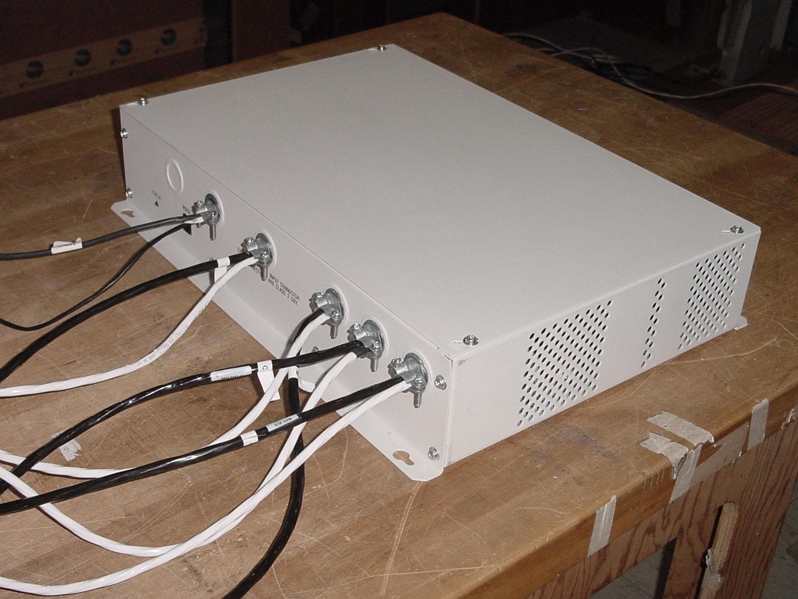
Click to zoom
Application Details
- Equipment Class
- FAP - Part 15 Anti-Pilferage Device
- Date of Grant
- Aug 26, 2010
- Application Purpose
- Original Equipment
- Date of Application
- Aug 26, 2010
- Equipment Note
- Anti-Pilferage Device
- Frequency Range
- 0.04500000 - 0.08900000
- Country
- United States
Documents & Files
Document Text
Text extracted from the exhibit documents filed with the FCC. Open a document above to read the original.
Users Manual
Preliminary AMC-7010 METAL FOIL DETECTION KIT 8200-2609-05, REV. 3 INSTALLATION GUIDE 1 of 24 AMC-7010 Metal Foil Detection Kit Installation Guide ZPMETAL-C4-7010 ZPMETAL-DET-7010 Contents About this Guide .................................................... 1 About the Product .................................................. 2 Features .......................................................... 2 Installation Requirements ...................................... 2 Installation ............................................................. 4 For Existing Systems ...................................... 4 Installing the Filter Board ................................ 5 Arranging the Pedestals ................................. 7 Wiring the AMC-7010 .... Error! Bookmark not defined. AC Hookup ...................................................... 9 Mounting the AMC-7010 ............................... 15 Downloading Files ........................................ 17 Tuning the Cap Board ................................... 18 Configuring the Metal Detection Settings ..... 20 Troubleshooting ............................................ 21 Configuring the Alarm Settings ..................... 22 Specifications ...................................................... 23 Declarations ........................................................ 23 About this Guide This guide explains how to install the AMC-7010, which is an option for the AMS-9050 controller that detects metal foil in dual, split, and quad pedestal systems. Other related documents are: Installation and Service Guide, AMS-9050 Controller, 8200-0537-02 Installation Guide, Ultra•Exit Transceiver Antennas, 8200-0537-16 Installation Guide, Metal Detection Filter Board, 8200-2609-04 Installation Guide, AMC-7000/7020 Metal Foil Detection Kit, 8200-2609-01 Note: Because customer requirements dictate the placement of system components, your Sensormatic representative will supply this information separately. Regulatory Restriction: The AMC-7010 Metal Foil Detection Kit requires that the Metal Detection Filter Board (ZPMETAL- UE-FLTR) be installed on the Ultra•Exit pedestals. Refer to the section entitled “Installing the Filter Board” on page 5 for guidelines on which pedestals require a filter board. Intended Use: Only install this device as described in this guide. © 2010 Sensormatic Electronics, LLC Preliminary AMC-7010 METAL FOIL DETECTION KIT 8200-2609-05, REV. 3 INSTALLATION GUIDE 2 of 24 About the Product The AMC-7010 Metal Foil Detection kit (ZPMETAL- DET-7010) covers split pedestal configurations. It also covers quad pedestal configurations with the addition of the ZPMETAL-DET-C4 kit. This AMS-9050 accessory detects metal having a large surface area, such as aluminum foil, when it passes between the pedestals of a system. It is designed to not detect metal objects with small continuous surfaces, such as keys and shopping carts. The kit can only be used with AMS-9050 controllers. The AMC-7010 is an accessory for AMS-9050 controllers connected to 2m Ultra•Exit pedestals (ZS1090, ZS1091, ZS1092and ZS1102) or 2.4m Ultra•Exit pedestals (ZS1130, ZS1131, ZS1121, and ZS1132) with the Integrated Traffic Flow option (ZPUE-TRAFFICNTR). Although the AMC-7010 can handle dual, split, or quad pedestal configurations, the AMC-7000 and AMC-7020 options are usually used for dual configurations. Features Automatic Detection Adjustment – the system adjusts itself to changes in the amount of metal in the environment. Enclosure is suitable for use in environmental air handling space other than ducts or plenums. Directional Inhibit support – using the People Counter option, system can be set to alarm for incoming metal only, out-going metal only, or both. Multiple alarm methods – the system can indicate the presence of metal foil by several methods: a visual alarm at the pedestal, an audio alarm at the pedestal, the triggering of a relay that connects to another device (such as a paging system), or an alarm at a digital remote alarm. Metal foil detection counts – the number of metal foil detections can be displayed on an optional Local Device Manager (LDM). Large coverage area – detects metal between two antennas up to 1.5m (5ft) off the floor between the two pedestals. Wired synchronization – synchronization of the controller with other controllers must be done with Universal Synchronization instead of wired synch because the Wired Synch port is needed for Metal Foil Detection. Installation Requirements Verifying Equipment and Unpacking Verify that all equipment has arrived. Ensure the system configuration is correct for the site. Unpack major components in a back room. At the install site, lay out parts in the order used. Do not clutter the aisle or cause a trip hazard. Installer/Contractor Have electrical work comply with the latest national electrical code, national fire code, and all applicable local codes and ordinances. Coordinate work with other trades to avoid interference. Verify existing site conditions and coordinate with the owner’s representative and appropriate utilities as required. Obtain copies of all related plans, specifications, shop drawings and addenda to schedule and coordinate related work. Thoroughly review the project to ensure that all work meets or exceeds the above requirements. Bring alleged discrepancies to the attention of Sensormatic Electronics. Mounting Requirements The AMC-7010 has a built-in flange used to attach the enclosure to a wall or ceiling using suitable hardware. Structure and hardware must support 25.6kg (56.4 lb) or four times the weight of the enclosure assembly. Do not mount enclosure with its fan facing up. Pedestal Placement Minimum distance between two Ultra*Exit pedestals is 1.2m (4.0ft) measured center-to- center. If there is another Metal Detection system in the area and the two closest pedestals of the system are within 11m (35ft) of each other, you must sync the AMS-9050 controllers with a Wired Sync option. P…
Text truncated - open the document above for the full version.
Cover Letter(s)
August 20, 2010 Timco Engineering, Inc. 849 N.W. State Road 45 P.O. Box 370 Newberry, Florida 32669 USA Re: Application for a Confidential Request for Anti-Pilferage Device, FCC ID: BVCAMC7010 Dear Sir or Madam: Federal Communications Commission Authorization and Evaluation Division Confidentiality Request regarding application for certification. Pursuant to Sections 0.457 and 0.459 of the Commission’s Rules, we hereby request confidential treatment of information accompanying this application as outlined below: AMC7010 Conf OpDes.pdf AMC7010 Conf Schem.pdf AMC7010 Conf BlkDia.pdf The above materials contain trade secrets and proprietary information not customarily released to the public. The public disclosure of these materials may be harmful to the applicant and provide unjustified benefits to its competitors. The applicant understands that pursuant to Section 0.457 of the Rules, disclosure of this application and all accompanying documentation will not be made before the date of the Grant for this application. Sincerely, William D. Owsley Principal EMC Engineer Compliance Engineering Tyco Retail Solutions Sensormatic Electronics, LLC. 6600 Congress Ave. Boca Raton, FL. 33487
External Photos
FCC ID: BVCAMC7010 IC: 3506A-AMC7010 External Photos FCC ID: BVCAMC7010 IC: 3506A-AMC7010
ID Label/Location Info
FCC ID: BVCAMC7010 IC: 3506A-AMC7010 Label Location Photos
ID Label/Location Info
2412-2334-53 Product Code: ZPMETAL-DET-7010 Type: AMC-7010 MFD:05-10 P/N: 0319-0019-01 REV : A S/N: ccctyyww123456 Rating: 100-120/200-240V~ 50-60Hz 2,5A (2.5A) Made in Mexico -0123 BARCODE FCC ID: BVCAMC7010 This device complies with part 15 of the FCC rules. Operation is subject to the following two conditions: (1) This device may not cause harmful interference, and (2) This device must accept any interference received, including interference that may cause undesired operation. This Class A digital apparatus complies with Canadian ICES-003. Cet appareil numérique de la classe A est confrome á la norme NMB-003 du Canada. IC: 3506A-AMC7010 NRTL N205
Internal Photos
FCC ID: BVCAMC7010 IC: 3506A-AMC7010 Internal Photos FCC ID: BVCAMC7010 IC: 3506A-AMC7010 1 PCB Photos – Top and Bottom FCC ID: BVCAMC7010 IC: 3506A-AMC7010 FCC ID: BVCAMC7010 IC: 3506A-AMC7010 Note ferrite on green wire ground
Test Report
Page 1 of 37 TYCO SAFETY PRODUCTS SENSORMATIC EMC TEST REPORT Model: AMC-7010 FCC ID: BVCAMC7010 IC: 3506A-AMC7010 Intentional Radiator FCC and IC 47 CFR, Part 15, Subpart B, AND Subpart C Industry Canada RSS GEN, ICES-003, RSS-210 Date: August 23, 2010 EMC Engineer Revision Reason Date Rev 1 Initial 8/23/2010 Page 2 of 37 1 SUMMARY OF RESULTS 1.1 47 CFR Part 15, Subpart B / Subpart C Part Parameter To Be Measured selected Comments SubPart B UNINTENTIONAL RADIATORS 15.107 Conducted Disturbance (Conducted Emissions, 0.15-30 MHz) X complies 15.109 Radiated Disturbance (Radiated Emissions, 30-1000 MHz) X complies SubPart C INTENTIONAL RADIATORS 15.207 Conducted Disturbance (Conducted Emissions, 0.15-30 MHz) X complies 15.209 Radiated Disturbance (Radiated Emissions, 0.009 plus MHz) X complies Compliance with 15.203 The antenna is a professionally installed external antenna employing a terminal style connector; therefore the antenna is compliant with the requirements of this clause. Compliance with 15.204 The only antenna type used with this transmitter is a loop. The loop with the highest gain (area x turns x current) has been used for testing and the transmit circuit adjusted for highest output. 1.2 IC RSS 210 Clause Parameter To Be Measured test comment 5.9.1 Emission Bandwidth X complies Page 3 of 37 1 SUMMARY OF RESULTS ................................................................................................................ 2 1.1 47 CFR Part 15, Subpart B / Subpart C ........................................................................................ 2 1.2 IC RSS 210 ................................................................................................................................... 2 2 DESCRIPTION AND CHARACTERISTICS OF THE EUT ............................................................. 4 2.1 Description and Characteristics of Equipment Under Test (EUT). .............................................. 4 2.1.1 Additional EUT Setup / Configuration Details ..................................................................... 4 2.2 CONSTRUCTION OF EQUIPMENT UNDER TEST (EUT) ..................................................... 5 2.2.1 Overview ............................................................................................................................... 5 2.2.2 Installation ............................................................................................................................. 5 2.3 EQUIPMENT RATINGS ............................................................................................................. 6 2.4 FREQUENCY and INTERNAL CLOCKS .................................................................................. 6 2.4.1 Marketing And Installation Environment .............................................................................. 7 2.5 TEST SET-UP BLOCK DIAGRAM ............................................................................................ 8 2.6 LIST OF PORTS .......................................................................................................................... 9 3 FCC TESTS ....................................................................................................................................... 10 3.1 Sample Calculation – Radiated & Conducted Emissions ........................................................... 10 3.1.1 Test Site Registration .......................................................................................................... 10 3.2 Conducted Emissions, FCC Part 15, Clause 15.107 And 15.207 ............................................... 11 3.3 Radiated Emissions, FCC Part 15, Clause 15.109 (Above 30 Mhz) ......................................... 14 3.4 Radiated Emissions, FCC Part 15, Clause 15.209 (Below 30 MHz) ........................................ 17 3.5 Occupied Bandwidth For IC ....................................................................................................... 19 4 EQUIPMENT LIST ........................................................................................................................... 24 5 ANTENNA FACTORS. .................................................................................................................... 25 6 Test Setup Photos .............................................................................................................................. 32 7 PCB Photos – Top and Bottom ......................................................................................................... 36 Page 4 of 37 2 DESCRIPTION AND CHARACTERISTICS OF THE EUT The type designation may be either a single alphanumeric code or an alphanumeric/code divided into two parts. TYPE DESIGNATION AS A SINGLE ALPHANUMERIC CODE: (See Note 1) A M S 7 0 1 0 OR TYPE DESIGNATION IN TWO PARTS: 1. EQUIPMENT SERIES No. (See Note 2) 2. EQUIPMENT SPECIFIC No. (See Note 3) Note 1: This is the manufacturer’s numeric or alphanumeric code or name that is specific to a particular equipment. It may contain information in coded form on the characteristics of the equipment e.g. frequency, power. The manufacturer is free to choose the form of the type designation. Note 2: This is the number, code or trade name used by the manufacturer to describe a series or “family” of equipment of substantially the same mechanical and electrical construction which will include a number of related equipments. This number is often referred to as the “model no.” Note 3: This is the manufacturer’s identification number given to specific equipment in the series or “family” of equipments. It is often referred to as the “identification number”. 2.1 Description and Characteristics of Equipment Under Test (EUT). Unit: AMC-7010 Power Pack Board Revision -02 Product Code: ZE7010 Part Number: 0319-0011-01 Regulatory ID: AMC-7010 2.1.1 Additional EUT Setup / Configuration Details Configurator Version: 6.11 Application Version: 1.0082 Page 5 of 37 2.2 C…
Text truncated - open the document above for the full version.
Test Setup Photos
FCC ID: BVCBIC7010 IC: 3506A-BIC7010 Test Setup Photos Radiated Emissions >30 MHz FCC ID: BVCBIC7010 IC: 3506A-BIC7010 Radiated Emissions <30 MHz FCC ID: BVCBIC7010 IC: 3506A-BIC7010 Conducted Emissions FCC ID: BVCBIC7010 IC: 3506A-BIC7010 Occupied Bandwidth
Contact Information
Applicant
Mark D. Alexis(Manager Regulatory Compliance)
Test Firm
Tyco Safety Products / SensormaticWilliam Owsley
[email protected]561-912-6462
Technical Specifications
| # | Rule Parts | Frequency Range | Power Output |
|---|---|---|---|
| 1 | 15C | 0.045 MHz - 0.089 MHz | - |
Other Applications from Tyco Safety Products/Sensormatic

BVCIDX5000
Jun 23, 2026UHF RFID Reader
Equipment Class
DSS - Part 15 Spread Spectrum TransmitterBVCAMS1137H
Dec 22, 2025Anti Theft System - Electronic Asset Security
Equipment Class
FAP - Part 15 Anti-Pilferage DeviceBVCAMB9012
Sep 10, 2024Label Deactivator Controller
Equipment Class
DCD - Part 15 Low Power Transmitter Below 1705 kHz
BVC-4000-PI26
Sep 24, 2015RM2L-4000-P126, RM2-4000-P126
Equipment Class
DXX - Part 15 Low Power Communication Device Transmitter
BVCAMS90604
May 20, 2014Anti-pilferage Device
Equipment Class
FAP - Part 15 Anti-Pilferage Device