BVCAMS9040-68KANTI-PILFERAGE DEVICE
Tyco Safety Products/Sensormatic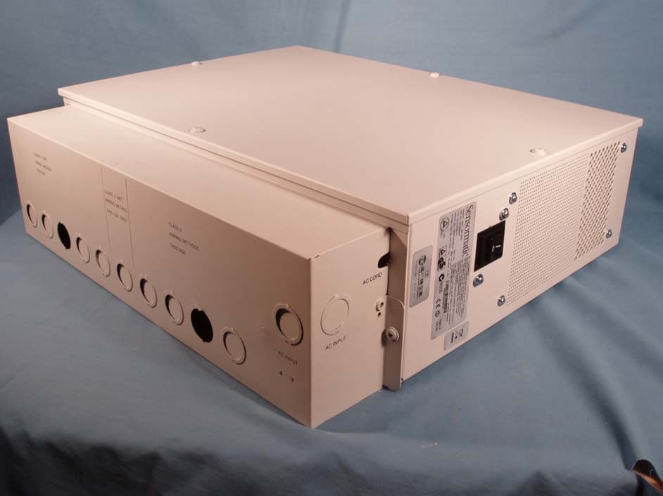
Click to zoom
Application Details
- Equipment Class
- FAP - Part 15 Anti-Pilferage Device
- Date of Grant
- Apr 08, 2008
- Application Purpose
- Original Equipment
- Date of Application
- Apr 07, 2008
- Equipment Note
- ANTI-PILFERAGE DEVICE
- Frequency Range
- 0.06800000 - 0.06800000
- Country
- United States
Documents & Files
Document Text
Text extracted from the exhibit documents filed with the FCC. Open a document above to read the original.
Users Manual
AMS-9040 CONTROLLER 8200-0367-02, REV. E INSTALLATION AND SERVICE GUIDE 1 of 22 AMS-9040 Controller Installation and Service Guide ZE9040, ZE9040-68K Contents To the Installer....................................................... 1 About the Product.................................................. 2 Basic Operation and Setup ................................... 2 Device Connections .............................................. 3 Installation Features .............................................. 7 Service Features ................................................... 8 Installation Requirements...................................... 9 Installation Procedure.......................................... 10 AC Hookup .......................................................... 12 System Setup ...................................................... 14 Redistributing the Load ....................................... 15 Special Rules for Floor Antennas........................ 16 Troubleshooting................................................... 17 Fuse Replacement .............................................. 19 Specifications ...................................................... 20 Declarations ........................................................ 21 Appendix A: Auto Synchronization...................... 22 To the Installer The AMS-9040 detection system consists of a ZE9040 controller and the following antennas: Non-European Installation Antenna Type Digital Euro Pro-Max 4 AMS-3003 System Digital Pro-Max 4 AMS-3004 System Digital Door-Max 4 AMS-3010 System Digital Floor-Max 4 AMS-3030 System AMS-3000 System AMS-3031 System © 2008 Sensormatic Electronics Corp. European Installation Antenna Type Digital Euro Pro-Max 4 Digital Pro-Max 4 Digital Door-Max 4 Digital Floor-Max 4 CAUTION: Ultra•Loop antennas cannot be installed with the AMS-9040 controller in EU countries. This installation and service guide explains how to install, setup, and service the AMS-9040 controller. Parts required to install this system are: • AMS-9040 Controller • Digital AM intelligent antennas (various) • AMS-9040 Service Configurator Software. Other documents that may be required for installation are: • AMS-9040 Detection System Planning Guide, 8200-0367-01 • Antenna Installation Guide (various) • AMS-9040 Controller Key Switch, 8200-0367-04 • AMS-9040/Digital 216 Controller Air Handling Kit, 8000-2693-11. Regulatory Restriction: In certain countries, there may be installation restrictions on the antennas. See antenna installation guides for restrictions, if any. Intended Use: Only install this device as described in this guide. Declaration of Conformity: If this product was installed in a European Union or European Free Trade Association member state, give the Declaration of Conformity included with this product to the manager or user. By law, this information must be provided to the user. • Because customer requirements dictate the placement of system components, your Sensormatic representative will supply this information separately. • Because of the number of antennas and accessories that can connect to this controller, methodically install this system to avoid problems. See “System Setup” in this guide for guidance on how to setup antennas. • Never restart or boot up a computer connected to an active controller. Doing so disables the mouse function on the computer. AMS-9040 CONTROLLER 8200-0367-02, REV. E INSTALLATION AND SERVICE GUIDE 2 of 22 About the Product The four-channel AMS-9040 controller is part of an EAS detector used to detect EAS tags/labels at store exit(s). Controller Features • Inputs for up to eight intelligent or non-intelligent antennas (four of which can be transceivers), up to four auxiliary receiver antennas, and up to four noise coils. Antenna coils can be set for phase flipping (default), aiding, or figure-8 operation. Note: Phase flipping is unavailable when noise coils are used. noise coils are used. • The controller is set up using a laptop computer and AMS-9040 service configurator software. • The controller is set up using a laptop computer and AMS-9040 service configurator software. • Controller-assisted tuning of intelligent antennas. • Controller-assisted tuning of intelligent antennas. • Wireless synchronization device such as a Sensormatic Sync Link can be used. • Wireless synchronization device such as a Sensormatic Sync Link can be used. • Up to two remote alarms and two beacon lamps can be powered and controlled. • Up to two remote alarms and two beacon lamps can be powered and controlled. • Up to four externally-powered alarm devices such as security cameras can be triggered. • Up to four externally-powered alarm devices such as security cameras can be triggered. • Sensormatic alarm management or people counting device can be powered and controlled. • Hardwired sync and transmit inhibit function connections. • RS-232 (for local diagnostics) and RS-485 (for remote diagnostics) support. Installation Features • Sits on a shelf or attaches to a wall or ceiling using a cable tray/mounting bracket assembly. The assembly secures to the controller using two captive ¼-turn fasteners. • Has 19 knockouts in the cable tray used to receive exposed cables or cables in conduit. Knockouts are available for Class 2 wiring from low voltage devices, Class 2 “wet” wiring from an alarm management device, and Class 3 wiring from transmit antennas. Three knockouts in the tray receive an exposed ac cable or cable in conduit. A U-shaped opening in the side of the tray allows access for a power cord, if used. Basic Operation and Setup The controller deters theft by activating an alarm when it detects the unique response of an active Ultra•Max hard plastic tag or disposable label. To detect a tag: • Antenna(s) connected to the controller emit a magnetic field close to the tag/label’s natural frequency causing it to vibrate or “ring” at the frequency of the field. When the field is removed, energy in the ta…
Text truncated - open the document above for the full version.
Cover Letter(s)
Tyco / Sensormatic Federal Communications Commission Authorization and Evaluation Division Confidentiality Request regarding application for certification of FCC ID: (BVCAMS9040-68K). Pursuant to Sections 0.457 and 0.459 of the Commission’s Rules, we hereby request confidential treatment of information accompanying this application as outlined below: AMS9040-68K_Conf Operational Description.pdf AMS9040-68K_Conf Schematic.pdf AMS9040-68K_Conf Block Diagram.pdf The above materials contain trade secrets and proprietary information not customarily released to the public. The public disclosure of these materials may be harmful to the applicant and provide unjustified benefits to its competitors. The applicant understands that pursuant to Section 0.457 of the Rules, disclosure of this application and all accompanying documentation will not be made before the date of the Grant for this application. Sincerely, (signature) William D. Owsley (printed name) Rev. 1/1/03
Cover Letter(s)
Tyco Safety Products / Sensormatic March 17, 2008 Federal Communications Commission Authorization and Evaluation Division 7435 Oakland Mills Road Columbia, MD 21046 Dear Sir or Madam: Sensormatic Electronics Corporation, 6600 Congress Avenue, Boca Raton, FL 33431 hereby requests certification for the Anti-Theft Device Model AMS-9040-68K [FCC ID: BVCAMS9040-68K] as set forth in the Federal Communication Commission's Rules and Regulations, Part 2 and 15. The AMS-9040-68K is a controller capable of driving a pair of antennas to generate a magnetic field to excite tags, receive the signal and alarm when an acceptable tag signal is detected and verified. The system operates at 68 kHz. The supported antenna sets for use with the AMS-9040-68K are the Digital Door-Max, Digital Floor-Max, Digital Pro-Max, Digital Euro Pro-Max, and Ultra Loop families of Sensormatic Electronics antennas. Sincerely, William D. Owsley Principal Compliance Engineer Tyco / Sensormatic Boca Raton, FL. 33487
External Photos
FCC ID: BVCAMS9040-68K IC: 3506A-AMS904068K AMS-9040-68K External Photos FCC ID: BVCAMS9040-68K IC: 3506A-AMS904068K
ID Label/Location Info
FCC ID: BVCAMS9040-68K IC: 3506A-AMS904068K AMS-9040 Label Position FCC ID: BVCAMS9040-68K IC: 3506A-AMS904068K Label Position The label is a metalized polyester th at is UL recognized and is permanen tly affixed using an L-23 adhesive.
ID Label/Location Info
2412-2334-42 N205 PRODUCT CODE: ZE9040-68K TYPE: AMS-9040 P/N: 0319-0016-01 REV: A SERIAL NO: ccctyyww123456 MFD: 04/08 100-120/200-240V~ 50-60Hz 5.0A BARCODE NRTL ASSEMBLED IN: Puerto Rico-0105 FCC ID: BVCAMS9040-68K This device complies with part 15 of the FCC rules. Operation is subject to the following two conditions: (1) This device may not cause harmful interference, and (2)This device must accept any interference received, including interference that may cause undesired operation. This Class A digital apparatus complies with Canadian ICES-003. Cet appareil numérique de la classe A est confrome á la norme NMB-003 du Canada. IC: 3506A-AMS904068K
Internal Photos
FCC ID: BVCAMS9040-68K IC: 3506A-AMS904068K AMS-9040-68K Internal Photos Internal Photo 1 FCC ID: BVCAMS9040-68K IC: 3506A-AMS904068K Internal Photo 2 – Board Top View FCC ID: BVCAMS9040-68K IC: 3506A-AMS904068K Internal Photo 3 – Board Bottom View
Test Report
Report AMS9040-68K Page 1 of 28 TYCO SAFETY PRODUCTS SENSORMATIC EMC TEST REPORT PRODUCT TESTED AMS9040-68K FCC ID: BVCAMS9040-68K IC: 3506A-AMS904068K FCC RULES 47 CFR, Part 15, Subparts B and C IC SPECIFICATIONS RSS-Gen:2007 / RSS-210e:2007 / ICES-003:2004 Test Report Number AMS9040-68K DATE 10/10/2007 Report AMS9040-68K Page 2 of 28 1 Summary of Results Test Reference Test Name Results 47 CER 15.107 CONDUCTED EMISSIONS COMPLIES 47 CER 15.109 RADIATED EMISSIONS COMPLIES 47 CFR 15.203 ANTENNA REQUIREMENTS COMPLIES 47 CFR 15.207 CONDUCTED EMISSIONS COMPLIES 47 CFR 15.209 RADIATED EMISSIONS COMPLIES RSS GEN: 4.6.1 OCCUPIED BANDWIDTH PROVIDED Report AMS9040-68K Page 3 of 28 TYCO SAFETY PRODUCTS............................................................................................................................. 1 SENSORMATIC................................................................................................................................................... 1 EMC........................................................................................................................................................................ 1 TEST REPORT..................................................................................................................................................... 1 1 Summary of Results........................................................................................................................................ 2 1.1 General Information................................................................................................................................4 1.1.1 Test Methodology........................................................................................................................... 4 1.1.2 Test Facility.................................................................................................................................... 4 1.1.3 Test System Description................................................................................................................. 4 2 List of Measuring Equipment......................................................................................................................... 6 3 FCC 15.203 Antenna Requirement................................................................................................................. 7 4 Conducted Emissions, FCC 15.107 and 15.207 ............................................................................................. 8 5 Radiated Emissions....................................................................................................................................... 14 5.1 Radiated Emissions, FCC 15.209, 30-1000 MHz................................................................................. 15 5.2 Radiated Emissions, FCC 15.209, below 30 MHz ............................................................................... 24 5.2.1 H- field data below 30 MHz, in particular 10 harmonics of the fundamental frequency............. 26 6 Occupied Bandwidth, RSS Gen 4.6.1 ........................................................................................................... 28 Report AMS9040-68K Page 4 of 28 1.1 General Information 1.1.1 Test Methodology Conducted and Radiated Emissions testing were performed according to the procedures in ANSI C63.4-2003, and the requirements of 15.31, 15.33, 15.35, 15.207, and 15.209. Radiated emissions measurements below 30MHz were performed at a distance 15 meters and the results were extrapolated to the distance specified per 15.31 and 15.209 according the 2-point extrapolation method. 1.1.2 Test Facility The shielded room conducted emissions measurement facility and the radiated emissions Open Area Test Site are located at Tyco / Sensormatic Electronics Corporation Headquarters at 6600 Congress Avenue, Boca Raton, Florida 33487. These sites have been found acceptable by and are on file with the FCC per FCC Registration Number 889978, and Industry Canada per file number IC 3506A-1. 1.1.3 Test System Description. The AMS-9040-68K is a controller capable of driving a pair of antennas to generate a magnetic field to excite tags, receive the signal and alarm when an acceptable tag signal is detected and verified. A single main PCB accommodates the Receiver, the Switching Amplifier Transmitter and the Power Supply. The AMS-9040-68K is intended to be paired with the following Sensormatic transmit antenna systems families: -Digital Door-Max -Digital Floor-Max -Digital Pro-Max -Digital Euro Pro-Max -Ultra Loop The worst-case radiated emissions data [below 30 MHz] was observed on the Ultra Loop Antenna. The worst case configuration was the vertical loop and the data reported is to that configuration. The product tested was a pre-production unit built to production drawings. Report AMS9040-68K Page 5 of 28 LIST OF PORTS Id Function Class Maximum Cable Length Test Length Cable Type A AC Mains* ac power > 1m but ≤ 3 m 6 18 AWG Cable B Transmit signal/control > 3 m 50 Shielded 2 Pairs [individual shields] + common drain [white] Belden-E E34372 C Transmit signal/control > 3 m 50 Shielded 4 wire Cable [individual shield] + common drain [white] Belden-E E34372 D External Receiver signal/control > 3 m 10 Shielded four wire cable [black] 22 AWG E116394 E Remote Alarm signal/control > 3 m 11 Shielded 2 Pairs [individual shields] + 1 common drain [black] 22 AWG – E118871 F Beacon Lamp signal/control > 3 m 26 Madison Cable 2 wire cable [shielded] G Relay Contact signal/control > 3 m 15 Madison Cable 2 wire cable [shielded] – same type as F H TX Inhibit signal/control > 3 m 14 Madison Cable 2 wire cable [shielded] – same type as F and G I RS232 signal/control > 3 m J RS485 Network signal/control > 3 m 20 Shielded 2 wire cable – Alpha AWG 24 K Sync Link signal/control <3m 9 Ribbon Cable [unshielded] L Ultra Link signal/control > 3 m 15 Alpha wire – 2 wire - unshielded M Wired Sync signal/control > 3 m N…
Text truncated - open the document above for the full version.
Test Setup Photos
AMS9040-68K EMC Test Report Setup Photos, Dated 10/10/2007 Conducted setup Photos of required line cord 3 meter compact chamber setup for frequency identification Typical OATS setup. H-Field setup
Contact Information
Applicant
Mark D. Alexis(Manager Regulatory Compliance)
Test Firm
Tyco Safety Products / SensormaticWilliam Owsley
[email protected]561-912-6462
Technical Specifications
| # | Rule Parts | Frequency Range | Power Output |
|---|---|---|---|
| 1 | 15C | 0.068 MHz - 0.068 MHz | - |
Other Applications from Tyco Safety Products/Sensormatic

BVCIDX5000
Jun 23, 2026UHF RFID Reader
Equipment Class
DSS - Part 15 Spread Spectrum TransmitterBVCAMS1137H
Dec 22, 2025Anti Theft System - Electronic Asset Security
Equipment Class
FAP - Part 15 Anti-Pilferage DeviceBVCAMB9012
Sep 10, 2024Label Deactivator Controller
Equipment Class
DCD - Part 15 Low Power Transmitter Below 1705 kHz
BVC-4000-PI26
Sep 24, 2015RM2L-4000-P126, RM2-4000-P126
Equipment Class
DXX - Part 15 Low Power Communication Device Transmitter
BVCAMS90604
May 20, 2014Anti-pilferage Device
Equipment Class
FAP - Part 15 Anti-Pilferage Device