BVCAMSUSUPANTI-PILFERGAE DEVICE
Tyco Safety Products/Sensormatic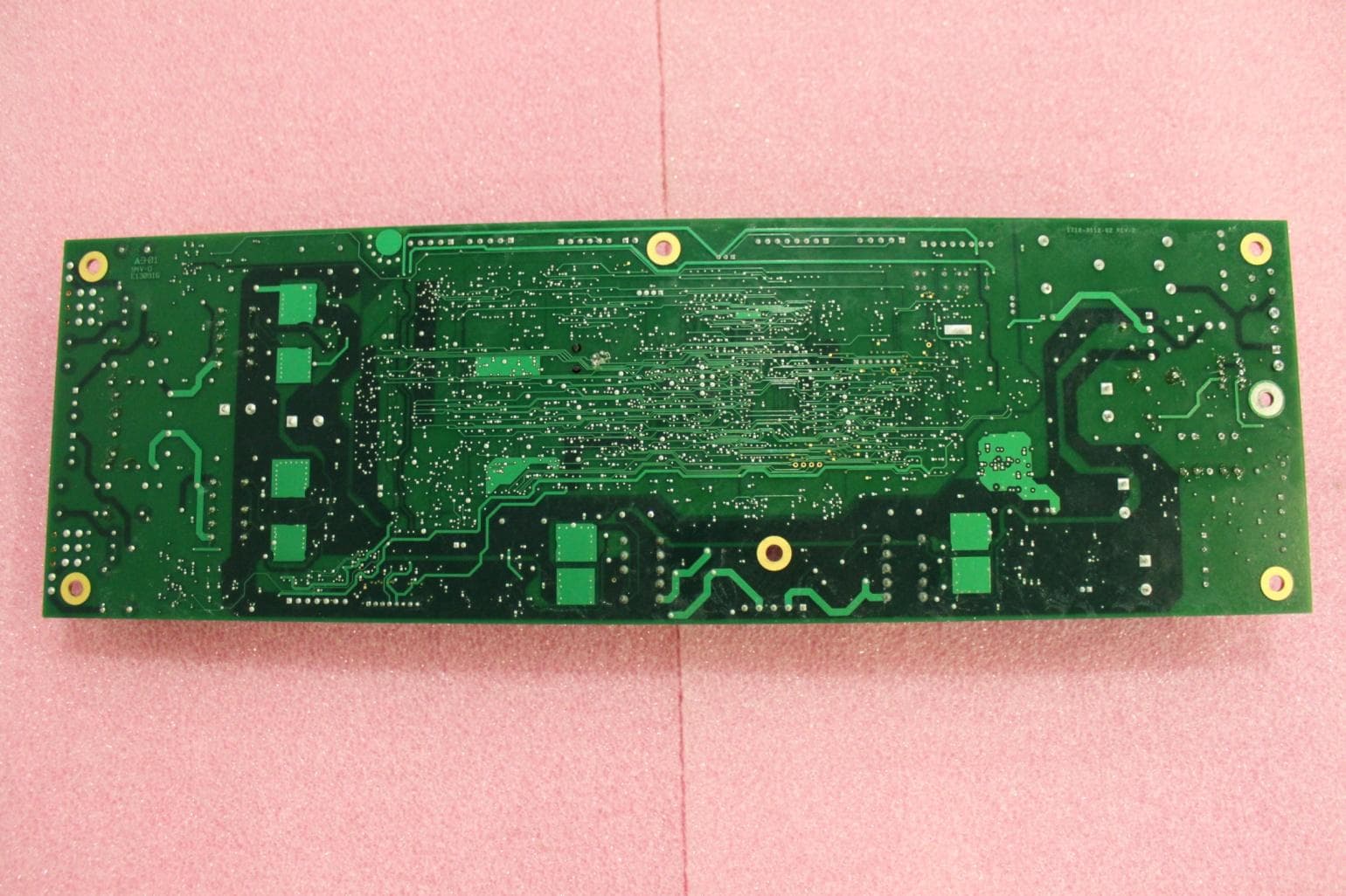
Click to zoom
Application Details
- Equipment Class
- FAP - Part 15 Anti-Pilferage Device
- Date of Grant
- Nov 07, 2011
- Application Purpose
- Original Equipment
- Date of Application
- Nov 07, 2011
- Equipment Note
- ANTI-PILFERGAE DEVICE
- Frequency Range
- 0.05800000 - 0.05800000
- Country
- United States
Documents & Files
Document Text
Text extracted from the exhibit documents filed with the FCC. Open a document above to read the original.
Users Manual
PRELIMINARY ULTRA•POST VI (AMS-1014) 8000-2595-30, REV. 4 INSTALLATION GUIDE 1 of 20 Ultra•Post ® VI (AMS-1014) Installation Guide ZS1014-P, ZS1014-S TYPE: AMS-1014 MODEL: AMS-USUP Contents About this Guide .................................................... 1 To the Installer ....................................................... 1 About the Product .................................................. 2 Installation Requirements ...................................... 4 Installing the Mounting Base ................................. 8 Connecting Options ............................................. 10 Connecting a Secondary Pedestal ...................... 12 Connecting an Auxiliary Receiver ....................... 14 Connecting to an UltraLink .................................. 14 Connecting Remote Alarms ................................ 15 Connecting Power ............................................... 16 Adjusting the Alarm Volume ................................ 17 Testing ................................................................. 17 Covering the Antenna Cables ............................. 17 Installing Crash Parts .......................................... 18 Specifications ...................................................... 19 Declarations ........................................................ 20 © 2011 Sensormatic Electronics, LLC. About this Guide This installation guide explains how to install the Ultra•Post VI (AMS-1014) detector. Other related documents are: Planning Guide, 8000-2595-03 (Rev F or later) Setup and Service Guide, 8000-2595-07 (Rev F or later) Reference Guide, 8000-2595-08 (Rev I or later) Install Guide, Ultra•Post People Counting 2 Option, 8000-2595-31 Note: Because customer requirements dictate the placement of detector components, your Sensormatic representative will supply this information separately. To the Installer Regulatory Restriction: none. Intended Use: Only install this device as described in this guide. Do Not Discard! Document may be needed by code inspectors. Leave it at the site until the installation is complete and the system has been approved. PRELIMINARY ULTRA•POST VI (AMS-1014) 8000-2595-30, REV. 4 INSTALLATION GUIDE 2 of 20 About the Product The Ultra•Post VI detector activates an alarm when it detects the unique response of an active Ultra•Max ® hard plastic tag or disposable label. Features The Ultra•Post VI detector is similar to the Ultra•Post IV detector; however it has the following additional features. Fan-less design for silent operation Improved noise immunity Hybrid-parallel design One design for world-wide use Auxiliary receivers have different connectors from the secondary pedestal so a secondary pedestal and two auxiliary receivers can be used at the same time. Options People Counting 2 Option (ZPUP-PC2-CBLKIT, ZPUE-PCNTR2) – adds people-counting hardware to the primary and secondary pedestals. Interconnect Cable (ZPUP-IC6-4M, ZPUP-IC6- 12M, ZPUP-IC6-15M) – connects a secondary pedestal to a primary pedestal. People Counting Cable (ZPUP-PCICBL-4M, ZPUP-PCICBL-12M, ZPUP-PCICBL-15M) – connects a people counting option in a secondary pedestal to a primary pedestal. Auxiliary receiver kits – extend the effective range of the detector. Supported kits are: Ranger Antenna Kit ZKRANGER-1, Satellite Antenna ZKRXMULLMT, and Amorphous Core receivers. Noise canceling receivers (ZKNC-R) – improve detection performance in high-noise environments. Crash Kit (0100-1089-01) – protects the detector from damage by shopping carts. Wired Synchronization Kit (ZPUE-WSYNC) – connects a primary Ultra•Post VI to another primary Ultra•Post VI to prevent them from interfering with each other. Alarm Counter (ZPCOUNT) – provides a running count of the number of alarms detected; it is installed in the base of the detector. Poster Panel (ZPUP-PSTPANEL) – allows advertising material to be affixed to pedestal. Detector Configurations A primary pedestal alone, a primary and secondary pedestal, or a primary pedestal with auxiliary receivers can be configured to cover different exit widths and to adapt to different architectural requirements. An auxiliary receiver consists of either one Satellite antenna or two Rangers. The different combinations are listed below and shown in Figure 1. 1. Single pedestal. One primary pedestal provides up to 0.9m (3ft) of coverage. In certain situations, the pedestal can protect two side-by-side exits. 2. Dual pedestal. One primary pedestal and one secondary pedestal are connected together to protect an exit up to 1.8m (6ft) wide. This configuration can operate in the following modes: Dual-Alternating, Simultaneous, Alternating, Backfield Reduction, and Alternating Backfield Reduction. 3. One primary pedestal flanked by two secondary pedestals. 4. Multiple primary pedestals. Two primary pedestals with a secondary pedestal connected to one of the primary pedestals. 5. Primary pedestal with single auxiliary receiver. One primary pedestal and a single auxiliary receiver are connected together. This configuration can operate in Transceiver- Ferrite mode or Backfield Reduction mode. 6. Primary pedestal with split auxiliary receivers. One primary pedestal and two auxiliary receivers are connected together. This configuration can be operated in the following modes: Ferrite-transceiver-Ferrite, Primary- only (split), and Primary-only (split alternating) 7. Dual pedestals with one auxiliary receiver. One primary pedestal and one secondary pedestal are separated by an auxiliary receiver in between. 8. Dual pedestals with two auxiliary receivers. One primary pedestal and one secondary pedestal are flanked by two auxiliary receivers. Not all coverage distances are shown. For information on coverage distances for other configurations and operating modes, refer to the Planning Guide. PRELIMINARY ULTRA•POST VI (AMS-1014) 8000-2595-30, REV. 4 INSTALLATION GUIDE 3 of 20 Figure 1. Configurations Single pedestal .9m (3ft) .9m (3ft) Primar…
Text truncated - open the document above for the full version.
Cover Letter(s)
October 20, 2011 Timco Engineering, Inc. 849 N.W. State Road 45 P.O. Box 370 Newberry, Florida 32669 USA Re: Application for a Confidential Request for Anti-Pilferage Device, FCC ID: BVCAMSUSUP Dear Sir or Madam: Federal Communications Commission Authorization and Evaluation Division Confidentiality Request regarding application for certification. Pursuant to Sections 0.457 and 0.459 of the Commission’s Rules, we hereby request confidential treatment of information accompanying this application as outlined below: AMSUSUP ConfOpDes.pdf AMSUSUP ConfSchemPri.pdf AMSUSUP ConfSchemSec.pdf AMSUSUP ConfBlkDia.pdf The above materials contain trade secrets and proprietary information not customarily released to the public. The public disclosure of these materials may be harmful to the applicant and provide unjustified benefits to its competitors. The applicant understands that pursuant to Section 0.457 of the Rules, disclosure of this application and all accompanying documentation will not be made before the date of the Grant for this application. Sincerely, William D. Owsley Principal EMC Engineer Compliance Engineering Tyco Retail Solutions Sensormatic Electronics, LLC. 6600 Congress Ave. Boca Raton, FL. 33487
Cover Letter(s)
October 20, 2011 Timco Engineering, Inc. 849 N.W. State Road 45 P.O. Box 370 Newberry, Florida 32669 USA Re: Application for a Limited Single Modular Request for Anti-Pilferage Device, FCC ID: BVCAMSUSUP Dear Sir or Madam: Federal Communications Commission Authorization and Evaluation Division Pursuant to Section 15.212 (b) of the Commission’s Rules; “(b) A limited modular approval may be granted for single or split modular transmitters that do not comply with all of the above requirements, e.g. , shielding, minimum signaling amplitude, buffered modulation/data inputs, or power supply regulation, if the manufacturer can demonstrate by alternative means in the application for equipment authorization that the modular transmitter meets all the applicable part 15 requirements under the operating conditions in which the transmitter will be used. Limited modular approval also may be granted in those instances where compliance with RF exposure rules is demonstrated only for particular product configurations. The applicant for certification must state how control of the end product into which the module will be installed will be maintained such that full compliance of the end product is always ensured.” This circuit board generates a series of 58 kHz pulses used to activate anti-pilferage tags and detect the resonance of those tags. The transmitter drives a set of loop antennas to establish a magnetic field that interacts with any tags present. These are the first two models of this present implementation. There are plans to add more loop antenna configurations and chassis to hold them. Using one transmitter board that can be used for each configuration would be an advantage in time to market. The transmitter does not comply with all the modular requirements. It is not shielded; the transmitter power is not regulated on board, it uses the regulation of the AC Mains; it has no buffered modulation or data inputs being a tuned resonant system that uses one frequency; it is not available to be installed into any other systems or units outside of the applicants control. Testing and results indicated in the test report, indicate that the transmitter meets the general radiated limits of 15.209 from 150 kHz to 1 GHz and also the conducted limits of 15.207. Therefore, as we the applicant will always maintain control of the end product by manufacturing the transmitter board into a variety of chassis with loop antennas, all to perform the same tuned resonant function of detecting anti-pilferage tags, we are applying for a Limited Modular approval. Sincerely, William D. Owsley Principal EMC Engineer Sensormatic Electronics, LLC. 6600 Congress Ave. Boca Raton, FL. 33487
External Photos
BVCAMSUSUP 1 EQUIPMENT UNDER TEST PHOTOS Controller board unmounted and turned over. BVCAMSUSUP Controller board mounted in primary pedestal. Cap board in Secondary pedestal BVCAMSUSUP UltraShield5, AMS-1003, primary pedestal Cap board in Secondary pedestal
ID Label/Location Info
BVCAMSUSUP THIS DRAWING MAY CONTAIN PATENTED OR PROPRIETARY INFORMATION AND MUST NOT BE USED FOR MANUFACTUR- ING OR ANY PURPOSE DETRI- MENTAL TO SENSORMATIC ELECTRONICS. ACCEPTANCE OF THIS DRAWING WILL BE CONSTRUED AS AN AGREE- MENT TO AND ACCEPTANCE OF THE FOREGOING. s FINISH N/A RELEASE APP’D APPROVALS DIMENSIONS ARE SHOWN IN: Millimeters DATE 8/12/10 SENSORMATIC ELECTRONICS CORP. BOCA RATON, FLORIDA SIZE A DRAWING NUMBER H2412-2526-01 TITLE LBL,TEMP,U*P VI PRIMARY REV 3 SHEET 1 OF 1 8/12/10 MATERIAL N/A CHECKED ENGR GOEDDERZ DRAWN CERASINI TOLERANCES ARE: DECIMALS ANGLES X.X = .5mm X.XX = .3mm 1/2 X.XXX = .1mm DEGREE MSWord REVISION LTR ER/ECN NO DESCRIPTION DATE BY APP’D 3 REVISED 3/8/11 RSC JG Removable Label for AMS-1014 (Ultra*Post VI) Specifications Overall size: (l x w) 125 x 150mm, maximum corner radii, 25mm. Colour: Black ink on White background Label Material:50LB white uncoated litho with 447 (removable, rubber based adhesive) Vendor part number “Technicote 50 EDP/TR447/65#” or equivalent. Adhesive: Adhesive to be applied to un-printed surface. Adhesive must allow the label to be removed easily up to three months after application, without leaving any tacky residue, or discoloration. Type: AMS-1014 VER 1014P
ID Label/Location Info
2412-2334-63 FCC ID: BVCAMSUSUP This device complies with part 15 of the FCC rules. Operation is subject to the following two conditions: (1) This device may not cause harmful interference, and (2)This device must accept any interference received, including interference that may cause undesired operation. This Class B digital apparatus complies with Canadian ICES-003. Cet appareil numérique de la classe B est confrome á la norme NMB-003 du Canada. ALL OUTPUTS ARE NEC CLASS 2 DRY, LPS (LIMITED POWER SOURCE) Part 1 of 2 for Model: AMS-1003 IC: 3506A-AMSUSUP Made in Mexico-0123 PRODUCT CODE: ZS1003-P TYPE: AMS-1003 REG ID: AMS-USUP P/N: 0304-3097-01 REV: A SERIAL NO: ccctyyww123456 MFD: 04/11 100-120/200-240V~ 50-60Hz 1.4/0.8A NRTL N205 BARCODE
ID Label/Location Info
2412-2334-59 FCC ID: BVCAMSUSUP This device complies with part 15 of the FCC rules. Operation is subject to the following two conditions: (1) This device may not cause harmful interference, and (2)This device must accept any interference received, including interference that may cause undesired operation. This Class B digital apparatus complies with Canadian ICES-003. Cet appareil numérique de la classe B est confrome á la norme NMB-003 du Canada. ALL OUTPUTS ARE NEC CLASS 2 DRY, LPS (LIMITED POWER SOURCE) Part 1 of 2 for Model: AMS-1014 IC: 3506A-AMSUSUP Made in Mexico-0123 PRODUCT CODE: ZS1014-P TYPE: AMS-1014 REG ID: AMS-USUP P/N: 0304-3092-01 REV: A SERIAL NO: ccctyyww123456 MFD: 04/11 100-120/200-240V~ 50-60Hz 1.4/0.8A NRTL N205 BARCODE
Internal Photos
BVCAMSUSUP 1 EQUIPMENT UNDER TEST PHOTOS Controller board unmounted and turned over. BVCAMSUSUP Controller board mounted in primary pedestal. Cap board in Secondary pedestal BVCAMSUSUP UltraShield5, AMS-1003, primary pedestal Cap board in Secondary pedestal
Test Report
FCC ID: BVCAMSUSUP IC: 3506A-AMSUSUP Page 1 of 30 TYCO / SENSORMATIC EMC TEST REPORT Model: AMS-1014 AMS-1003 FCC ID: BVCAMSUSUP IC: 3506A-AMSUSUP Intentional Radiator FCC and IC 47 CFR, Part 15, Subpart B, and Subpart C Industry Canada ICES-003e, RSS GENi3, RSS-210i8 Date: October 11, 2011 EMC Engineer 6600 Congress Ave. Boca Raton, FL. 33487 USA Revision A Oct. 11, 2011 Initial FCC ID: BVCAMSUSUP IC: 3506A-AMSUSUP Page 2 of 30 1 SUMMARY OF RESULTS ..................................................................................................................... 3 1.1 47 CFR Part 15, Subpart B / Subpart C ............................................................................................. 3 1.2 IC RSS 210 (RSS GEN) ................................................................................................................... 3 1.3 European Transmitter Tests, EN 300 330-2 / EN 300 330-1 ............................................................ 4 1.4 European EMC Tests, EN 301 489-1 as modified by EN 301 489-3 ............................................... 4 2 DESCRIPTION AND CHARACTERISTICS OF THE EUT ................................................................. 5 2.1 Description and Characteristics of Equipment Under Test (EUT). ................................................... 5 2.1.1 Additional EUT Setup / Configuration Details .......................................................................... 5 2.1.2 Type Designation ....................................................................................................................... 5 2.1.3 Construction Of Equipment Under Test (EUT) ......................................................................... 6 2.1.4 Overview .................................................................................................................................... 6 2.1.5 A limited modular approval ....................................................................................................... 6 2.1.6 Installation .................................................................................................................................. 6 2.1.7 Equipment Ratings ..................................................................................................................... 7 2.1.8 Frequency Characteristics And Internal Clocks ......................................................................... 7 2.1.9 Marketing And Installation Environment ................................................................................... 7 2.2 Test Site Registration ........................................................................................................................ 8 2.3 Test Procedures ................................................................................................................................. 8 2.4 Sample Calculation – Radiated & Conducted Emissions ................................................................. 8 2.5 Uncertainty of Measurements ......................................................................................................... 10 3 TEST SET-UP BLOCK DIAGRAM ..................................................................................................... 11 4 FCC TESTS ............................................................................................................................................ 12 4.1.1 Conducted Emissions, FCC Part 15, Clause 15.107 And 15.207 ............................................ 12 4.1.2 Radiated Emissions, FCC Part 15, Clause 15.109 and 15.209 (above 30 MHz) .................... 15 4.1.3 Radiated Emissions, FCC Part 15, Clause 15.209 (below 30 MHz) ....................................... 18 4.1.4 Occupied Bandwidth For Industry Canada – IC. ..................................................................... 21 5 EQUIPMENT LIST ............................................................................................................................... 23 6 ANTENNA FACTORS. ......................................................................................................................... 24 FCC ID: BVCAMSUSUP IC: 3506A-AMSUSUP Page 3 of 30 1 SUMMARY OF RESULTS 1.1 47 CFR Part 15, Subpart B / Subpart C Part PARAMETER TO BE MEASURED Applies Comments SubPart B, Unintentional Radiators (Class B) 15.107 Conducted Disturbance (Conducted Emissions, 0.15-30 MHz) X Complies 15.109 Radiated Disturbance (Radiated Emissions, 30-x000 MHz) X Complies SubPart C, Intentional Radiators (General Limit) 15.207 Conducted Disturbance (Conducted Emissions, 0.15-30 MHz) X Complies 15.209 Radiated Disturbance (Radiated Emissions, 0.009 plus x MHz) X Complies Compliance with 15.203: This product is professionally installed and setup, therefore the device is compliant with the requirement of this clause. Compliance with 15.204: The only antenna type used with this transmitter is a loop. The loop with the highest gain (area x turns x current) has been used for testing and the transmit circuit adjusted for highest output. 1.2 IC RSS 210 (RSS GEN) Clause PARAMETER TO BE MEASURED Applies comment 4.6.1 Emission Bandwidth - -20 dBc X Complies 4.6.2 6 dB Bandwidth FCC ID: BVCAMSUSUP IC: 3506A-AMSUSUP Page 4 of 30 1.3 European Transmitter Tests, EN 300 330-2 / EN 300 330-1 (Product Class 1; Receiver Class 2) Clause PARAMETER TO BE MEASURED Applies comment Transmitter Requirements 5.2.1 / 7.2.1 RADIATED H- FIELD X Complies 5.2.1 / 7.3 PERMITTED RANGE OF OPERATING FREQ X Complies 5.2.1 / 7.4 PERMITTED RANGE OF MODULATION BW X Complies 5.2.1 / 7.5.3 RADIATED EMISSIONS <30 MHZ X Complies 5.2.1 / 7.5.4 RADIATED EMISSIONS =>30 MHZ X Complies 1.4 European EMC Tests, EN 301 489-1 as modified by EN 301 489-3 Clause PARAMETER TO BE MEASURED Applies comment Emissions parameters 8.4 CONDUCTED EMISSIONS ON AC MAINS (EN55022) X Complies 8.5 HARMONIC CURRENT (EN 61000-3-2, sec. 7 note 1) X < 75W, Complies 8.6 VOLTAGE FLUCTUATATIONS (EN…
Text truncated - open the document above for the full version.
Test Setup Photos
BVCAMSUSUP 1 PHOTOS OF TEST SETUPS 1.1 Conducted Emissions AC Mains BVCAMSUSUP 1.2 E-field testing on OATS Worst case, all peripherals included. Typical case, all peripherals located remote. BVCAMSUSUP BVCAMSUSUP 1.3 H-field testing at OATS BVCAMSUSUP 1.4 Occupied Bandwidth
Contact Information
Applicant
Mark D. Alexis(Manager Regulatory Compliance)
Test Firm
SensormaticWilliam Owsley
[email protected]5619126462
Technical Specifications
| # | Rule Parts | Frequency Range | Power Output |
|---|---|---|---|
| 1 | 15C | 0.058 MHz - 0.058 MHz | - |
Other Applications from Tyco Safety Products/Sensormatic

BVCIDX5000
Jun 23, 2026UHF RFID Reader
Equipment Class
DSS - Part 15 Spread Spectrum TransmitterBVCAMS1137H
Dec 22, 2025Anti Theft System - Electronic Asset Security
Equipment Class
FAP - Part 15 Anti-Pilferage DeviceBVCAMB9012
Sep 10, 2024Label Deactivator Controller
Equipment Class
DCD - Part 15 Low Power Transmitter Below 1705 kHz
BVC-4000-PI26
Sep 24, 2015RM2L-4000-P126, RM2-4000-P126
Equipment Class
DXX - Part 15 Low Power Communication Device Transmitter
BVCAMS90604
May 20, 2014Anti-pilferage Device
Equipment Class
FAP - Part 15 Anti-Pilferage Device