BVCBIC4170Indoor Ceiling Mount Surveillance Transceiver
Tyco Safety Products/Sensormatic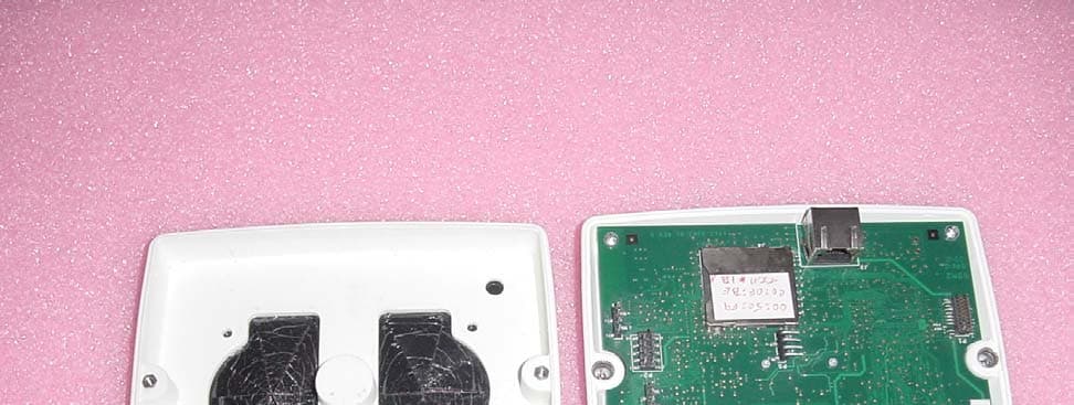
Click to zoom
Application Details
- Equipment Class
- DSS - Part 15 Spread Spectrum Transmitter
- Date of Grant
- Aug 19, 2010
- Application Purpose
- Original Equipment
- Date of Application
- Aug 19, 2010
- Equipment Note
- Indoor Ceiling Mount Surveillance Transceiver
- Frequency Range
- 2402.00000000 - 2480.00000000
- Country
- United States
Documents & Files
Document Text
Text extracted from the exhibit documents filed with the FCC. Open a document above to read the original.
Users Manual
BIS-4170 IVS PEOPLE COUNTER 8200-2702-01, REV. 4A INSTALLATION AND PLANNING GUIDE 1 of 23 BIS-4170 IVS People Counter Installation and Planning Guide For Mounting Heights: 2.4–4.3m (8–14ft) To the Installer WARNING! Install the people counter IVS device in an air space not used for environmental air. DO NOT install the IVS device in a plenum or other environmental air-handling space. For indoor use only. Cables placed in environmental airspace must be plenum rated unless the cables are in raceways. Contents About the People Counter ..................................... 2 Mounting Considerations....................................... 5 Installation Procedure............................................ 7 Running the Cables............................................ 8 Mounting the IVS Device ................................... 9 To a Ceiling Tile ............................................ 10 To a Ceiling T-Bar......................................... 10 To a Wall....................................................... 11 To Wood or Sheetrock Ceilings .................... 12 Connecting Video, Communications, and Power to the IVS Device ........................... 13 Verification Test ............................................... 15 Specifications ...................................................... 22 Declarations ........................................................ 22 Appendix A: Site Survey Form .......................... 23 © 2010 Sensormatic Electronics, LLC ! BIS-4170 IVS PEOPLE COUNTER 8200-2702-01, REV. 4A INSTALLATION AND PLANNING GUIDE 2 of 23 About the People Counter Mounted at ceiling heights up to 4.3m (14ft), the IVS People Counter device (Figure 1) tracks the paths of people within its field-of-view (Figure 2). The IVS device can cover an entrance up to 2.4m (8ft). The IVS device is also capable of reporting counts to a remote location through one of the following dedicated communication interfaces: • Ethernet • LDM II via RS-485 • Bluetooth. Figure 1. IVS device Figure 2. IVS device field-of-view BIS-4170 IVS PEOPLE COUNTER 8200-2702-01, REV. 4A INSTALLATION AND PLANNING GUIDE 3 of 23 Coverage Ceiling-mounted up to a height of 4.3m (14ft), the IVS device can cover a doorway or opening up to 2.4m (8ft) wide. The IVS device is powered by a 48Vdc Power over the Ethernet (PoE) device. Tracking A floor-facing camera in the IVS device is used to determine the height of a desired target (adults), and thus to distinguish them from undesired targets such as shopping carts, pets, and children. • A count line is projected across the entrance. The line is a virtual trip wire you draw on the video image where the “feet” of the person tracked are to be counted. • The count line can be set to trigger the count from a person crossing it while entering an area. • A person entering an area is counted as one “enter”. A person exiting an area is counted as one “exit”. • A personal computer is used to setup the IVS device and view what it detects. Downloaded or web-based setup software displays the camera image. BIS-4170 IVS PEOPLE COUNTER 8200-2702-01, REV. 4A INSTALLATION AND PLANNING GUIDE 4 of 23 Figure 3. IVS device orientation Hardware Features BIS-4170 IVS PEOPLE COUNTER 8200-2702-01, REV. 4A INSTALLATION AND PLANNING GUIDE 5 of 23 Mounting Considerations Perform a site survey (Appendix A) while observing the installation site for the following considerations. Ceiling Considerations • Composition: Sheet rock, plaster, suspended ceiling. The IVS device can attach to any 1/4-20 thread-per-inch bolt of a customer mounting bracket. • Height: The IVS device can be mounted up to a height of 4.3m (14ft). CAUTION: The tilt of the IVS device should follow the slope of the floor. The setup software can adjust IVS device settings for unavoidable tilt, as long as it is less than 10 degrees of the floor slope (placeholder, TBD). CAUTION: Mounting over stairs or highly sloped floors is not recommended (placeholder, TBD). • Access: Check for in-ceiling obstacles such as ceiling vents and fire sprinklers. • Location: Mount the IVS device in such a way that its field-of-view is centered over the entry/exit corridor. Also, do not mount the IVS device to capture people through glass or other translucent surfaces (placeholder, TBD). BIS-4170 IVS PEOPLE COUNTER 8200-2702-01, REV. 4A INSTALLATION AND PLANNING GUIDE 6 of 23 Traffic Corral Points Check for walls, displays and anti-theft pedestals that help corral traffic. Ideally, the traffic path should be elongated as much as possible under the IVS device. PoE Device The PoE device supplied with the IVS device is typically placed in computer wiring room or next to the IVS device near a convenient power outlet. The PoE comes with a 1.8m (6ft) power cable. Other Considerations • 24-hour or timed power available. • Cable distance from IVS device to computer wiring room: DO NOT exceed a maximum of 100m (330ft). • Network switch type and ports available. BIS-4170 IVS PEOPLE COUNTER 8200-2702-01, REV. 4A INSTALLATION AND PLANNING GUIDE 7 of 23 Installation Procedure Parts Required • DVR for verification testing (The DVR records video data “seen” by the IVS device.) • Cat5 cable • IVS device • ¼-20 threaded rod • ¼-20 nuts (2) Optional Parts* ? BIS-4170 IVS PEOPLE COUNTER 8200-2702-01, REV. 4A INSTALLATION AND PLANNING GUIDE 8 of 23 Running the Cables Run a Cat5 cable from the installation site for the IVS device to the installation site for the PoE. Run another cable from the PoE to the store’s computer wiring room. Note: Cat5 cable runs cannot exceed 100m (330ft) without using a repeater. Terminate cables following Error! Reference source not found. below. • Use plenum / non-plenum cable per local requirements. • Use pre-manufactured patch cables when available. • Leave a sufficient service loop at end of each home run. • Test all cables. Most on-site issues are cable related. Table 1. Ethernet cable pin assignments Pin Wire Color 1 WHT / ORG 2 ORG 3 WHT / …
Text truncated - open the document above for the full version.
Cover Letter(s)
July 28, 2010 Federal Communications Commission 7435 Oakland Mills Road Columbia MD 21046 Subject: Request for Confidentiality FCC ID: BVCBIC4170 To Whom It May Concern: Pursuant to the provisions of Sections 0.457 and 0.459 of the Commission’s rules (47 CFR §§ 0.457, 0.459), we are requesting the Commission to withhold the following attachments as confidential document from public disclosure indefinitely. BIC4170 Conf OperationalDescription BIC4170 Conf Schematic BIC4170 Conf Block Diagram Above mentioned document contains detailed system and equipment description are considered as proprietary information in operation of the equipment. The public disclosure of above documents might be harmful to our company and would give competitor an unfair advantage in the market. The applicant understands that pursuant to Section 0.457 of the Rules, disclosure of this application and all accompanying documentation will not be made before the date of the Grant for this application. Sincerely, William D. Owsley Principal EMC Engineer Compliance Engineering Sensormatic Electronics, LLC. Tyco Retail Solutions Tyco Safety Products 6600 Congress Ave. Boca Raton, FL. 33487
Cover Letter(s)
July 28, 2010 Compliance Certification Services Certification Division 47173 Benicia Street Fremont, CA 94538 To whom it may concern: We, the undersigned, hereby authorize the Compliance Certification Services and hereafter referred to as CCS, to act on our behalf in all manners relating to application for equipment authorization, including signing of all documents relating to these matters. Any and all acts carried out by CCS on our behalf shall have the same effect as acts of our own. We, the undersigned, hereby certify that we are not subject to a denial of federal benefits, that includes FCC benefits, pursuant to Section 5301 of the Anti-Drug Abuse Act of 1988, 21 U.S.C. 853(a). In authorizing Compliance Certification Services as our agent, we still recognize that we are responsible to: a) comply with the relevant provisions of the certification program; b) make all necessary arrangements for the conduct of the evaluation, including provision for examining documentation and access to all areas, records (including internal audit reports) and personnel for the purposes of evaluation (e.g. testing, inspection, assessment, surveillance, reassessment) and resolution of complaints; c) make claims regarding certification only in respect of the scope for which certification has been granted; d) do not use our product certification in such a manner as to bring the Certification Division into disrepute and not make any statement regarding our product certification which the Certification Division may consider misleading or unauthorized; e) upon suspension or cancellation of certification, discontinue use of all advertising matter that contains any reference thereto and return any certification documents as required by the Certification Division; f) use certification only to indicate the products are certified as being in conformity with specified standards; g) endeavor to ensure that no certificate or report nor any part thereof is used in a misleading manner; h) ensure that any reference to our product certification in communication media such as documents, brochures or advertising, complies with the requirements of the Certification Division; i) keep a record of all complaints made known to the us relating to the product’s compliance with requirements of the relevant standard and to make these records available to the Certification Division when requested; j) take appropriate action with respect to such complaints and any deficiencies found in products or services that affect compliance with the requirements for certification; k) document the actions taken. This authorization is valid until further written notice from the applicant. Sincerely Yours, William D. Owsley Principal EMC Engineer Compliance Engineering Sensormatic Electronics, LLC. Tyco Retail Solutions Tyco Safety Products 6600 Congress Ave. Boca Raton, FL. 33487
External Photos
External photos Face Back Opened
ID Label/Location Info
FCC ID: BVCBIC4170 IC: 3506A-BIC4170 BIC-4170-1U This device complies with part 15 of the FCC Rules. Operation is subject to the following two conditions: (1) This device may not cause harmful interference, and (2) this device must accept any interference received, including interference that may cause undesired operation. FCC and IC Label Location One FCC/IC label will be placed in the position indicated. This is an outside surface. One Regulatory label (white rectangle in photo) will be attached to PCB. This is visible during installation.
Internal Photos
Internal Photos Face Back
Test Report
FCC CFR47 PART 15 SUBPART C INDUSTRY CANADA RSS-210 ISSUE 7 CERTIFICATION TEST REPORT FOR INDOOR CEILING MOUNT SURVEILLANCE TRANSCEIVER MODEL NUMBER: BIC-4170-1U FCC ID: BVCBIC4170 IC: 3506A-BIC4170 REPORT NUMBER: 10U13213-1, Revision A ISSUE DATE: AUGUST 16, 2010 Prepared for TYCO SAFETY PRODUCTS SENSORMATIC 6600 CONGRESS AVENUE BOCA RATON, FL 33487, U.S.A. Prepared by COMPLIANCE CERTIFICATION SERVICES 47173 BENICIA STREET FREMONT, CA 94538, U.S.A. TEL: (510) 771-1000 FAX: (510) 661-0888 REPORT NO: 10U13213-1A DATE: AUGUST 16, 2010 FCC ID: BVCBIC4170 IC: 3506A-BIC4170 Page 2 of 116 COMPLIANCE CERTIFICATION SERVICES FORM NO: CCSUP4701C 47173 BENICIA STREET, FREMONT, CA 94538, USA TEL: (510) 771-1000 FAX: (510) 661-0888 This report shall not be reproduced except in full, without the written approval of CCS. Revision History Rev. Issue Date Revisions Revised By -- 07/26/10 Initial Issue F. Ibrahim A 08/16/10 Updated Antenna Gain T. Chan REPORT NO: 10U13213-1A DATE: AUGUST 16, 2010 FCC ID: BVCBIC4170 IC: 3506A-BIC4170 Page 3 of 116 COMPLIANCE CERTIFICATION SERVICES FORM NO: CCSUP4701C 47173 BENICIA STREET, FREMONT, CA 94538, USA TEL: (510) 771-1000 FAX: (510) 661-0888 This report shall not be reproduced except in full, without the written approval of CCS. TABLE OF CONTENTS 1. ATTESTATION OF TEST RESULTS.................................................................................... 5 2. TEST METHODOLOGY ........................................................................................................ 6 3. FACILITIES AND ACCREDITATION.................................................................................... 6 4. CALIBRATION AND UNCERTAINTY .................................................................................. 6 4.1. MEASURING INSTRUMENT CALIBRATION ............................................................... 6 4.2. SAMPLE CALCULATION.............................................................................................. 6 4.3. MEASUREMENT UNCERTAINTY................................................................................ 6 5. EQUIPMENT UNDER TEST ................................................................................................. 7 5.1. DESCRIPTION OF EUT................................................................................................ 7 5.2. MAXIMUM OUTPUT POWER....................................................................................... 7 5.3. DESCRIPTION OF AVAILABLE ANTENNAS............................................................... 7 5.4. SOFTWARE AND FIRMWARE..................................................................................... 7 5.5. WORST-CASE CONFIGURATION AND MODE .......................................................... 7 5.6. DESCRIPTION OF TEST SETUP................................................................................. 8 6. TEST AND MEASUREMENT EQUIPMENT ....................................................................... 10 7. ANTENNA PORT TEST RESULTS .................................................................................... 11 7.1. BASIC DATA RATE GFSK MODULATION................................................................. 11 7.1.1. 20 dB AND 99% BANDWIDTH............................................................................ 11 7.1.2. HOPPING FREQUENCY SEPARATION ............................................................ 15 7.1.3. NUMBER OF HOPPING CHANNELS................................................................. 17 7.1.4. AVERAGE TIME OF OCCUPANCY.................................................................... 22 7.1.5. OUTPUT POWER ............................................................................................... 25 7.1.6. AVERAGE POWER ............................................................................................ 29 7.1.7. CONDUCTED SPURIOUS EMISSIONS............................................................. 30 7.2. ENHANCED DATA RATE 8PSK MODULATION........................................................ 39 7.2.1. 20 dB AND 99% BANDWIDTH............................................................................ 39 7.2.2. HOPPING FREQUENCY SEPARATION ............................................................ 43 7.2.3. NUMBER OF HOPPING CHANNELS................................................................. 45 7.2.4. AVERAGE TIME OF OCCUPANCY.................................................................... 50 7.2.5. OUTPUT POWER ............................................................................................... 53 7.2.6. AVERAGE POWER ............................................................................................ 57 7.2.7. CONDUCTED SPURIOUS EMISSIONS............................................................. 58 8. RADIATED TEST RESULTS .............................................................................................. 67 8.1. LIMITS AND PROCEDURE ........................................................................................ 67 8.2. TRANSMITTER ABOVE 1 GHz .................................................................................. 68 8.2.1. BASIC DATA RATE GFSK MODULATION......................................................... 68 8.2.2. ENHANCED DATA RATE 8PSK MODULATION ................................................ 77 REPORT NO: 10U13213-1A DATE: AUGUST 16, 2010 FCC ID: BVCBIC4170 IC: 3506A-BIC4170 Page 4 of 116 COMPLIANCE CERTIFICATION SERVICES FORM NO: CCSUP4701C 47173 BENICIA STREET, FREMONT, CA 94538, USA TEL: (510) 771-1000 FAX: (510) 661-0888 This report shall not be reproduced except in full, without the written approval of CCS. 8.3. WORST-CASE BELOW 1 GHz................................................................................... 86 8.3.1. ORIGINAL POE................................................................................................... 86 8.3.2. POE # 1 (S/N: 02114) ................................…
Text truncated - open the document above for the full version.
Test Setup Photos
REPORT NO: 10U13213-1A DATE: AUGUST 16, 2010 FCC ID: BVCBIC4170 IC: 3506A-BIC4170 Page 109 of 116 COMPLIANCE CERTIFICATION SERVICES FORM NO: CCSUP4701C 47173 BENICIA STREET, FREMONT, CA 94538, USA TEL: (510) 771-1000 FAX: (510) 661-0888 This report shall not be reproduced except in full, without the written approval of CCS. 10. SETUP PHOTOS ANTENNA PORT CONDUCTED RF MEASUREMENT SETUP ANTENNA PORT CONDUCTED PHOTO REPORT NO: 10U13213-1A DATE: AUGUST 16, 2010 FCC ID: BVCBIC4170 IC: 3506A-BIC4170 Page 110 of 116 COMPLIANCE CERTIFICATION SERVICES FORM NO: CCSUP4701C 47173 BENICIA STREET, FREMONT, CA 94538, USA TEL: (510) 771-1000 FAX: (510) 661-0888 This report shall not be reproduced except in full, without the written approval of CCS. RADIATED RF MEASUREMENT SETUP X-AXIS PHOTO REPORT NO: 10U13213-1A DATE: AUGUST 16, 2010 FCC ID: BVCBIC4170 IC: 3506A-BIC4170 Page 111 of 116 COMPLIANCE CERTIFICATION SERVICES FORM NO: CCSUP4701C 47173 BENICIA STREET, FREMONT, CA 94538, USA TEL: (510) 771-1000 FAX: (510) 661-0888 This report shall not be reproduced except in full, without the written approval of CCS. Y-AXIS PHOTO REPORT NO: 10U13213-1A DATE: AUGUST 16, 2010 FCC ID: BVCBIC4170 IC: 3506A-BIC4170 Page 112 of 116 COMPLIANCE CERTIFICATION SERVICES FORM NO: CCSUP4701C 47173 BENICIA STREET, FREMONT, CA 94538, USA TEL: (510) 771-1000 FAX: (510) 661-0888 This report shall not be reproduced except in full, without the written approval of CCS. Z-AXIS PHOTO REPORT NO: 10U13213-1A DATE: AUGUST 16, 2010 FCC ID: BVCBIC4170 IC: 3506A-BIC4170 Page 113 of 116 COMPLIANCE CERTIFICATION SERVICES FORM NO: CCSUP4701C 47173 BENICIA STREET, FREMONT, CA 94538, USA TEL: (510) 771-1000 FAX: (510) 661-0888 This report shall not be reproduced except in full, without the written approval of CCS. RADIATED RF MEASUREMENT SETUP RADIATED FRONT PHOTO REPORT NO: 10U13213-1A DATE: AUGUST 16, 2010 FCC ID: BVCBIC4170 IC: 3506A-BIC4170 Page 114 of 116 COMPLIANCE CERTIFICATION SERVICES FORM NO: CCSUP4701C 47173 BENICIA STREET, FREMONT, CA 94538, USA TEL: (510) 771-1000 FAX: (510) 661-0888 This report shall not be reproduced except in full, without the written approval of CCS. RADIATED BACK PHOTO REPORT NO: 10U13213-1A DATE: AUGUST 16, 2010 FCC ID: BVCBIC4170 IC: 3506A-BIC4170 Page 115 of 116 COMPLIANCE CERTIFICATION SERVICES FORM NO: CCSUP4701C 47173 BENICIA STREET, FREMONT, CA 94538, USA TEL: (510) 771-1000 FAX: (510) 661-0888 This report shall not be reproduced except in full, without the written approval of CCS. POWERLINE CONDUCTED EMISSIONS MEASUREMENT SETUP LINE CONDUCTED FRONT PHOTO REPORT NO: 10U13213-1A DATE: AUGUST 16, 2010 FCC ID: BVCBIC4170 IC: 3506A-BIC4170 Page 116 of 116 COMPLIANCE CERTIFICATION SERVICES FORM NO: CCSUP4701C 47173 BENICIA STREET, FREMONT, CA 94538, USA TEL: (510) 771-1000 FAX: (510) 661-0888 This report shall not be reproduced except in full, without the written approval of CCS. END OF REPORT LINE CONDUCTED BACK PHOTO
Contact Information
Applicant
Mark D. Alexis(Manager Regulatory Compliance)
Test Firm
Compliance Certification ServicesThu Chan
Technical Specifications
| # | Rule Parts | Frequency Range | Power Output |
|---|---|---|---|
| 1 | 15C | 2.40 GHz - 2.48 GHz | 370.00 µW |
Other Applications from Tyco Safety Products/Sensormatic

BVCIDX5000
Jun 23, 2026UHF RFID Reader
Equipment Class
DSS - Part 15 Spread Spectrum TransmitterBVCAMS1137H
Dec 22, 2025Anti Theft System - Electronic Asset Security
Equipment Class
FAP - Part 15 Anti-Pilferage DeviceBVCAMB9012
Sep 10, 2024Label Deactivator Controller
Equipment Class
DCD - Part 15 Low Power Transmitter Below 1705 kHz
BVC-4000-PI26
Sep 24, 2015RM2L-4000-P126, RM2-4000-P126
Equipment Class
DXX - Part 15 Low Power Communication Device Transmitter
BVCAMS90604
May 20, 2014Anti-pilferage Device
Equipment Class
FAP - Part 15 Anti-Pilferage Device