BVCCCWAccess Control Reader
Tyco Safety Products/Sensormatic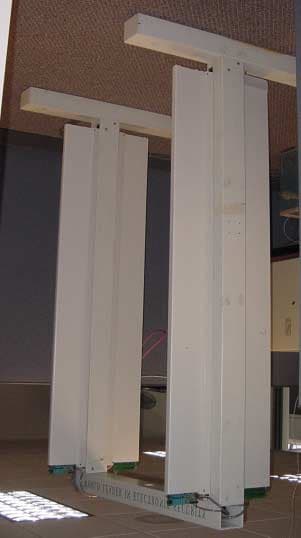
Click to zoom
Application Details
- Equipment Class
- DCD - Part 15 Low Power Transmitter Below 1705 kHz
- Date of Grant
- Jun 12, 2001
- Application Purpose
- Original Equipment
- Date of Application
- Jun 12, 2001
- Equipment Note
- Access Control Reader
- Frequency Range
- 0.13420000 - 0.13420000
- Country
- United States
Documents & Files
Document Text
Text extracted from the exhibit documents filed with the FCC. Open a document above to read the original.
Users Manual
8000-2803-01 A CïCURE Æ Watch Installation and Service Guide Access Systems CïCURE Watch Installation and Service Guide COPYRIGHT 2001 All rights reserved. No part of this manual may be reproduced in any form without written permission from Sensormatic Electronics Corporation. 8000-2803-01, Rev. 0/A SHF 5/01 WARNING Do not install this product in hazardous areas where highly combustible or explosive products are stored or used. WARNING The CïCURE Watch installation must be performed by qualified service personnel and should conform to all local codes. The reader/controller enclosure does not contain user serviceable parts. Contact Technical Support at 1-800-392-2873 for help in resolving system performance issues. FCC COMPLIANCE FCC COMPLIANCE: This equipment complies with Part 15 of the FCC rules for Class A digital devices when installed and used in accordance with the instruction manual. Following these rules provides reasonable protection against harmful interference from equipment operated in a commercial area. This equipment should not be installed in a residential area as it can radiate radio frequency energy that could interfere with radio communications, a situation the user would have to fix at their own expense. DISCONNECT DEVICE A 20A max., disconnect device, which also provides short circuit and overload protection, and has a minimum 3mm open circuit clearance, in accordance with the National Electric Code and applicable local codes must be installed at a location readily accessible to the equipment. EQUIPMENT MODIFICATION CAUTION Equipment changes or modifications not expressly approved by Sensormatic Electronics Corporation, the party responsible for FCC compliance, could void the user's authority to operate the equipment and could create a hazardous condition. WARRANTY DISCLAIMER Sensormatic Electronics Corporation makes no representation or warranty with respect to the contents hereof and specifically disclaims any implied warranties of merchantability or fitness for any particular purpose. Further, Sensormatic Electronics Corporation reserves the right to revise this publication and make changes from time to time in the content hereof without obligation of Sensormatic Electronics Corporation to notify any person of such revision or changes. LIMITED RIGHTS NOTICE For units of the Department of Defense, all documentation and manuals were developed at private expense and no part of it was developed using Government Funds. The restrictions governing the use and disclosure of technical data marked with this legend are set forth in the definition of ìlimited rightsî in paragraph (a) (15) of the clause of DFARS 252.227.7013. Unpublished - rights reserved under the Copyright Laws of the United States. CïCURE, Sensormatic, and the Sensormatic logo are registered trademarks of Sensormatic Electronics Corporation. Other product names (if any) mentioned herein may be trademarks or registered trademarks of other companies. CïCURE Watch Installation and Service Guide1 Table of Contents Error! Bookmark not defined. Table of Contents ........................................................................................................ 1 Chapter 1 ................................................................................................................... 1-1 Introduction............................................................................................................... 1-1 Product Overview................................................................................................. 1-2 Access Badges and Asset Tags .......................................................................... 1-2 Handheld Reader ................................................................................................. 1-2 RF Readers.......................................................................................................... 1-2 Antennas........................................................................................................ 1-2 RF Controller ................................................................................................. 1-3 RF Reader Configuration............................................................................... 1-3 Specifications ....................................................................................................... 1-4 Electrical ........................................................................................................ 1-4 Environmental................................................................................................ 1-5 Regulatory ..................................................................................................... 1-5 Chapter 2 ................................................................................................................... 2-1 Basic Functionality................................................................................................... 2-1 Basic System Operation ...................................................................................... 2-2 RF Controller Block .............................................................................................. 2-3 Synchronization Circuitry............................................................................... 2-3 Communications Interfaces ........................................................................... 2-3 Chapter 3 ................................................................................................................... 3-1 Planning..................................................................................................................... 3-1 RF Passage Reader Configurations .................................................................... 3-2 Single-Antenna Configurations...................................................................... 3-2 Multiple-Antenna Configurations .............................................................…
Text truncated - open the document above for the full version.
Cover Letter(s)
Sensormatic Electronics Corporation 951 Yamato Road, Boca Raton, FL 33431- 0700 Telephone (561) 989-7000 FAX (561) 989-7548 June 7, 2001 Amended November 13, 2001 Timco Engineering, Inc. 849 N.W. State Road 45 P.O. Box 370 Newberry, Florida 32669 USA Re: Request for withholding from public disclosure proprietary information submitted pursuant to an application for certification for a low power transmitter. FCC ID: BVCCCW Dear Sir or Madam: Sensormatic Electronics Corporation requests certain materials submitted with this application for certification of device FCC ID: BVCCCW be withheld from public disclosure. This request is made under the provision of 47 CFR 0.457 (d) and 5 USC 552(b)(4) Freedom of Information Act, Trade Secrets. The items for which confidentiality is requested include the block diagram, schematic diagrams and printed circuit card photos. The information contains proprietary information (trade secrets) regarding the circuit operation and capabilities (specific values of components, circuit design details and system architecture) which are the result of our extensive investment in research and development. Without the disclosed information, competitive organizations would take considerable more time to assess and develop a workable competitive product. As a result, we believe that disclosure of these company-guarded materials would compromise our leading position in this market. The equipment is installed and maintained by Sensormatic authorized and trained individuals. The circuitry is not directly viewable by the public or the users during use or after use. We therefore formally request that the materials identified “Confidential” be kept strictly confidential and not made available for inspections by any other party, except on a need to know basis for the sole purpose of the certification process. Sincerely, Donald J. Umbdenstock Sr. Principal Engineer, Compliance Engineering
External Photos
Figure 1. 4 Antenna Array, Transmitter cap photo insert. Figure 2. Reader Enclosure
ID Label/Location Info
PRODUCT CODE: CW-RID-1 REG ID: RFID CCW P/N: 0100-2474-01 REV : A SERIAL NO: SECA0117012345 RATING: 100-240V~ 2.0A 50-60Hz FCC ID: BVCCCW THIS DEVICE COMPLIES WITH PART 15 OF THE FCC RULES. OPERATION IS SUBJECT TO THE FOLLOWING TWO CONDITIONS: (1) THIS DEVICE MAY NOT CAUSE HARMFUL INTERFERENCE, AND (2) THIS DEVICE MUST ACCEPT ANY INTERFERENCE RECEIVED, INCLUDING INTERFERENCE THAT MAY CAUSE UNDESIRED OPERATION. REFER TO INSTALL GUIDE 8000-2803-01 REV _ ALL OUTPUTS ARE LPS (LIMITED POWER SOURCE) ACCESS CONTROL SYSTEM UNIT 9J89 MADE IN PUERTO RICO
ID Label/Location Info
Location of Regulatory Label containing FCC ID, compliance statement
Operational Description
Ccure Watch RF Product Description The CcureWatch product is an access control and asset management system utilizing Texas Instrument’s TIRIS RFID technology. The system embodies the process of identifying TIRIS badges and tags that are within a 3-foot radius of a transceiver antenna. The CCure Watch equipment includes a Reader Box with built in OEM power supply, two antenna types with built in transceiver board, and Hardware for mounting the antenna. Cables, which run from the Reader to each antenna, are to be supplied by the installer. The antenna is mounted on either side of a secured entrance/exit. Depending on the level of performance, 3 or 6-foot openings will require one, two or four antenna configurations. Additional cabling is required for synchronization, communications to an Access control panel and RF grounding. Reader box The reader box is a wall mounted electronics box. AC power is provided via metallic conduit to the mains input located at the bottom of the box. Alternatively, systems requiring non-metallic conduit includes a strain relief and a separate RF ground wire. The RF ground wire must be less than 6 feet long, 12 gauge in diameter and connected to the building ground. The reader has been tested to UL294 and as such can be mounted in Plenum space when electrical codes permit. The functions of the reader box are to: 1. Provide an interface to the Access control panel via RS485 2. Provide the electronic decoding of the TIRIS tag or badge signals that transverse the secured opening 3. Provide a means for system configuration for up to four antennas 4. Provide power, synchronization and control for the attached antennas The transmit signal originates from the reader and is conveyed to the antenna through the control cable. The receive signal is a differential analog signal that is brought from the antenna to the reader through the control cable as well. Each antenna has three status LED’s that are controlled by the reader and has separate control signals within the control cable. This cable is a shielded eight- conductor minimum 22 AWG twisted pair bundle. The shield is terminated at the reader only. A two conductor 16 AWG cable from the Reader box provides power to the antenna. The maximum length of either cable is 150 feet. The reader provides communications to the access control panel via RS485. This cable is a shielded 22 AWG twisted pair. The shield is terminated at the Reader and the access control panel and may be as long as 1000 feet. When communicating with the access control panel, the reader uses a standard Sensormatic RM READER protocol. Depending on the on-board rotary switch settings, the reader may be seen (by the access control panel) as one, two, three or four different RM READERS. To eliminate reader receiver interference, a synchronization of all readers is provided through the RS422 port in a master slave daisy chain arrangement. Finally, the reader provides two controlled 12-volt outputs and two auxiliary supervised inputs. All are monitored and controlled by the access panel via the RM protocol. Antenna (transceiver) There are two types of antennas, type A and type B. Both antennas are loop antennas, have two sections, top and bottom and provide an aperture size of 29.8 cm 2 . The A type antenna is wound in such a way as to provide a stronger field in the top section for main badge orientations. The B-type antenna may be thought of as an A-type turned upside down and consequently provides a stronger field in the bottom section of the Antenna. The antenna can be mounted on a wall or doorpost using mounting hardware and brackets provided by the factory. The antenna includes a transceiver PCB (RFI board) that provides drive to the series resonant circuit. Tuning the antenna is accomplished by a set of capacitors that are activated by jumpers provided by the factory. Standard Operations A typical access control system begins with the microprocessor turning on the transmitter for 50 milliseconds. A badge, which is within the systems specified range, is charged up and awaits the transmitter to turn off. During the transmit phase, the following processes are occurring: • DSP is executing through external system memory at 40 MIPS • The μP is executing through on chip flash memory • Serial data is transferred from the DSP to the μP • The CPLD divides down the 40MHz clock to 134.2KHz (Transmit signal) • The RF transmit signal (134.2KHz) is conveyed to two of the four RF transmitter driver boards (RFI) • The RFI buffers the transmit signal and drives the 60 watt antenna using a half bridge driver circuit • The 60 watts needed to drive the antenna is provided by an OEM 15V 130-watt resonant mode switching power supply. This voltage is stepped up to 16 volts before power is separately cabled to the RFI. • To prevent interference, all readers within a specified distance are synchronized by the μP through the RS422 port. This port produces a 50 millisecond pulses by the master Reader and sent to all slave Readers which will align their transmit periods with the master’s pulse. After 50 milliseconds, the system enters the receive mode which is initiated by the μP turning off the transmit signal. During the Receive mode the following processes are occurring: • The badge or tag detects the end of the transmit mode and sends it’s FSK data • The RFI receives this signal, buffers it and sends the signal differentially to the Reader board. • The Reader analog section amplifies and demodulates the signal removing the mixer components as well as attenuating out of band noise prior to digitizing by the ADC. • The ADC samples the data at 106KHz and serially sends the data to the DSP. At the same time, the daughter card performs the same task on a separate signal from another antenna. Allowing for two antenna receptions per transmit and receive cycle. • The ADC runs from a 6.8MHz clock. • The DSP buffers the data from both the Reader ADC and the Daughter card and waits unt…
Text truncated - open the document above for the full version.
Test Report
FCC ID: BVCCCW 1 COMPANY Sensormatic Electronics Corp. 951 Yamato Road Boca Raton, Florida PRODUCT TESTED Ccure Watch RFID System FCC RULES 15.207, 15.209 TEST DATE May 9-31, 2001 SUBMITTED BY Donald J. Umbdenstock FCC ID: BVCCCW 2 INDEX I. SUMMARY OF RESULTS 3 II. GENERAL INFORMATION 3 Test Methodology 3 Test Facility 3 System Description 4 15.203 Compliance 4 III. CONDUCTED EMISSIONS TESTING, 15.207 4 IV. RADIATED EMISSIONS TESTING, 15.209 5 V. (This section intentionally blank) 5 VI. LIST OF MEASUREMENT EQUIPMENT 6 VII. DATA 7 Part A – Conducted Emissions 7 Part B – Radiated Emissions 9 FCC ID: BVCCCW 3 I. Summary of Results 47 CFR 15.207 CONDUCTED EMISSIONS COMPLIES 47 CFR 15.209 RADIATED EMISSIONS COMPLIES II. General Information 1.1 Test Methodology Both conducted and radiated emissions testing were performed according to the procedures in ANSI C63.4-1992, and the requirements of 15.31, 15.33, 15.35, 15.207, and 15.209. Radiated emissions measurements below 30 MHz were performed at a distance of 10 meters and the results extrapolated to the distance specified per 15.31 and 15.209. 1.2 Test Facility Measurements per 15.207 and 15.209 were performed at Sensormatic Electronics Corporation. The shielded room conducted emissions measurement facility is located at Sensormatic Electronics Corporation Headquarters at 951 Yamato Road, Boca Raton, Florida, 33431. The radiated emissions Open Area Test Site is located at Sensormatic Electronics Corporation manufacturing location, 6600 Congress Avenue, Boca Raton, Florida 33487. These sites have been found acceptable by and are on file with the FCC per FCC letter 31040/SIT 1300F2. FCC ID: BVCCCW 4 1.3 Test System Description. The CcureWatch system consists of a card reader, an access control card, a transceiver located in the loop antenna assembly, and interface circuitry to access control electronics in remote panels. The system can be configured with 1 to 4 antennas. A ground wire is provided for rfi mitigation. The product tested was a pre-production unit. 15.203 . The antenna is contained internally to the transceiver and is permanently attached, thus it is compliant with the requirements of this clause. III. Conducted Emissions Conducted emissions data are presented in Section VII “Data”, Part A “Conducted Emissions”. The product demonstrated compliance with the requirements of 15.207. The product was tested at 120 V, 60 Hz. FCC ID: BVCCCW 5 IV. Magnetic Field Radiated Emissions Radiated emissions data for this product are presented in Section VII “Data”, Part B “Radiated Emissions”. The product demonstrated compliance with the requirements of 15.209. Radiated emissions measurements were performed at 10 meters. Propagation loss was determined measuring the emissions at 10 meters and extrapolating the results to 300 meters and 30 meters as required for the frequency of interest. Maximum radiation was determined by first assessing symmetry while applying incremental rotation of the turntable in the preliminary measurements. The product exhibited quadrant symmetry. Measurements were taken at radials of 22.5° throughout one quadrant; the measurement antenna was rotated for maximum pickup about the vertical axis of the measurement antenna at each radial. The maximum emission was determined to be with the measurement loop antenna in the vertical polarization, parallel to the plane of the transmit antenna. The emissions were also greater for the single antenna configuration that for multiple antenna configurations due to phase cancellation of the multi-antenna configuration. Therefore the final data were recorded for the single antenna configuration. The product was tested at input voltages ranging from 102 – 138 V, 60 Hz with no measurable change in transmitter output. V. (This section intentionally left blank) FCC ID: BVCCCW 6 VI. LIST OF MEASURING EQUIPMENT The equipment used for determining compliance of the Ultra Post system with the requirements of 15.207 and 15.209 is marked with an “X” in the first column of the table below. Model Description Vendor Serial # X ALP -70 Loop Antenna Electro Metrics 163 X 3110B Biconnical Antenna Electro Metrics 1017 X 3146 Log Periodic Antenna EMCO 3909 3825/2 Line Imp Stable Network EMCO 1562 X 3816/2NM Line Imp Stable Network EMCO 9703 1064 6060B Frequency Generator Giga-tronics 5850202 FM2000 Isotropic Field Monitor Amplifier Research 15171 FP2000 Isotropic Field Probe Amplifier Research 15214 888 Leveler Amplifier Research 14998 75A220 Low Band Amplifier Amplifier Research 15208 10W1000A High Band Amplifier Amplifier Research 15138 PEFT Junior EFT Generator Haefely Trench 083 180-16 PEFT Junior Capacitive Cable Clamp Haefely Trench 083-078-31 NSG435 ESD Simulator Schaffner 1197 NSG431 ESD Simulator Schaffner 1267 X HP8591EM EMC Analyzer Hewlett - Packard 3520A00190 Power Source Pacific Instruments F-2031 EM Injection Clamp Fischer Cust. Comm. 30 FCC-801-M3-16 Coupling Decoupling Nwk Fischer Cust. Comm. 58 FCC-801-M3-16 Coupling Decoupling Nwk Fischer Cust. Comm. 59 F-33-1 RF Current Probe Fischer Cust. Comm. 304 EM 7600 Transient Limiter Electro-Metrics 187 Roberts Ant Tunable Dipole Set Compliance Design 003282 Roberts Ant Tunable Dipole Set Compliance Design 003283 HP8594E Spectrum Analyzer Hewlett Packard 3246A00300 X HP8447F Opt 64 Dual Preamplifier Hewlett Packard 2805A03473 FCC ID: BVCCCW 7 VII. Data Part A contains conducted emissions data; Part B contains radiated emissions data. Part A Conducted Emissions Project Name Conducted Emissions FCC Class B Filename RFID_CcureWatch_CondEMI_FCC_5-31-01.doc EUT Name CCureWatch Legacy Mode Serial Number Engineer Ron Devoe Phone Number Date of Test 05/31/2001 8:39:54 AM Test Name Conducted Emission Reg. Technician Stephen Krizmanich Comments Line In 120vac 60hz: Ferrite clamp (Ferrico F5NF130) on Line cord inside enclosure near barrier strip. External ground wire (6 foot 12 AWG) attached to chassis inside enclosure and line service box. Signal List Signal …
Text truncated - open the document above for the full version.
Test Setup Photos
Conducted Emissions Set-Up
Contact Information
Applicant
Mark D. Alexis(Manager Regulatory Compliance)
Test Firm
Sensormatic Electronics CorporationWilliam Elliott
Technical Specifications
| # | Rule Parts | Frequency Range | Power Output |
|---|---|---|---|
| 1 | 15C | 0.1342 MHz - 0.1342 MHz | - |
Other Applications from Tyco Safety Products/Sensormatic

BVCIDX5000
Jun 23, 2026UHF RFID Reader
Equipment Class
DSS - Part 15 Spread Spectrum TransmitterBVCAMS1137H
Dec 22, 2025Anti Theft System - Electronic Asset Security
Equipment Class
FAP - Part 15 Anti-Pilferage DeviceBVCAMB9012
Sep 10, 2024Label Deactivator Controller
Equipment Class
DCD - Part 15 Low Power Transmitter Below 1705 kHz
BVC-4000-PI26
Sep 24, 2015RM2L-4000-P126, RM2-4000-P126
Equipment Class
DXX - Part 15 Low Power Communication Device Transmitter
BVCAMS90604
May 20, 2014Anti-pilferage Device
Equipment Class
FAP - Part 15 Anti-Pilferage Device