BVCDEACHHAnti-theft equipment accessory
Tyco Safety Products/Sensormatic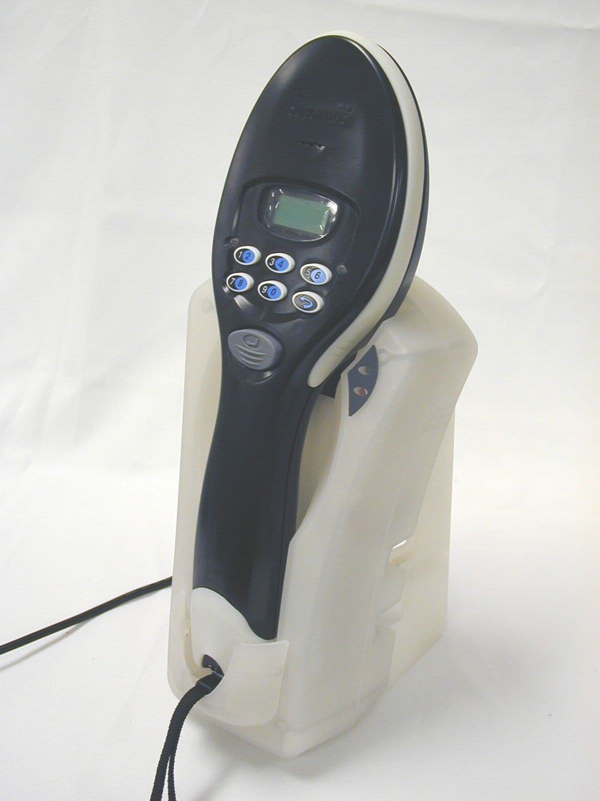
Click to zoom
Application Details
- Equipment Class
- FAP - Part 15 Anti-Pilferage Device
- Date of Grant
- Aug 06, 2000
- Application Purpose
- Original Equipment
- Date of Application
- Jul 19, 2000
- Equipment Note
- Anti-theft equipment accessory
- Frequency Range
- 0.05800000 - 0.05800000
- Country
- United States
Documents & Files
Document Text
Text extracted from the exhibit documents filed with the FCC. Open a document above to read the original.
Users Manual
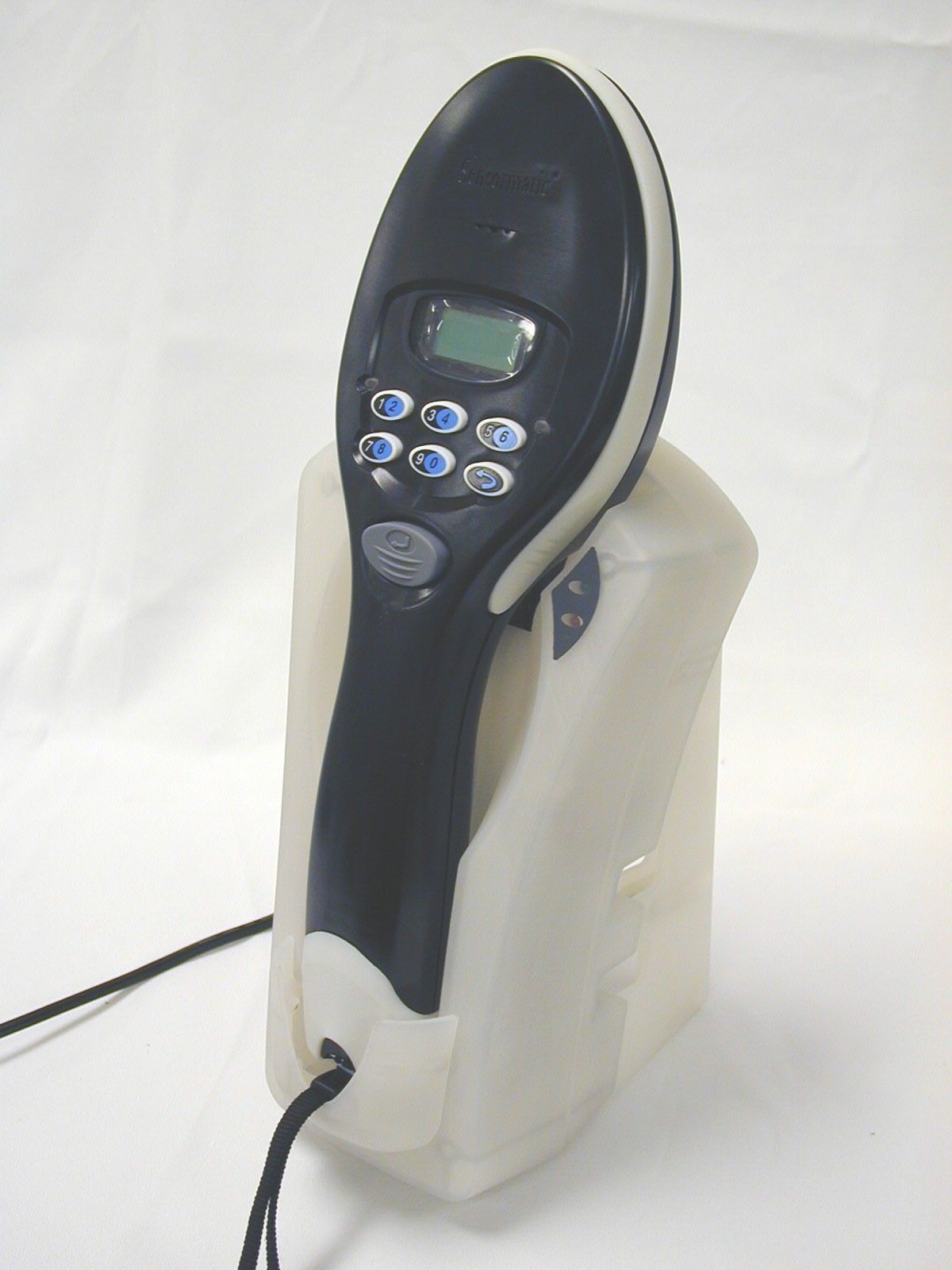
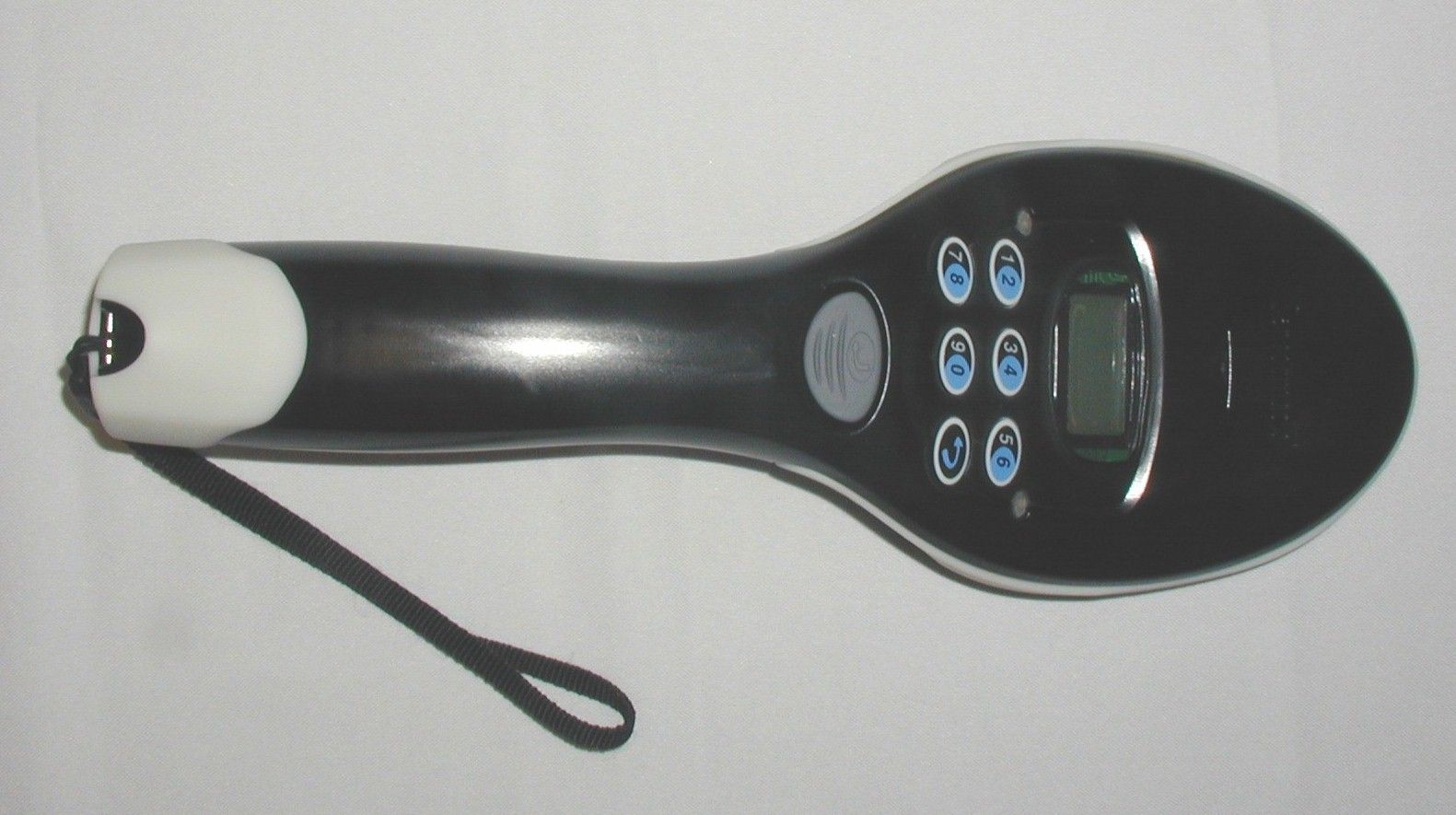
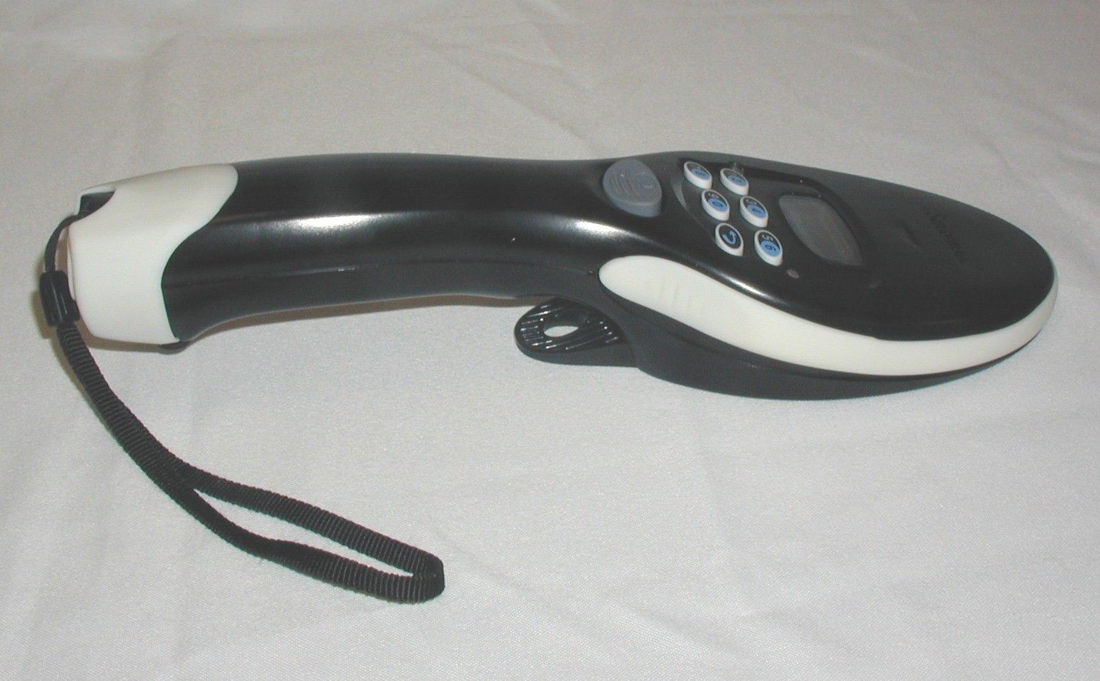
WORLD L EADER IN EL ECTRONIC SE CURITY User’s Guide (Preliminary) © Sensormatic 2000 HAND HELD DEACTIVATOR 8000-2738-01, REV. 0 1 Ultra•Max ® Hand Held Deactivator ™ About the Unit The Ultra•Max hand-held deactivator (HHD) is a battery-operated, rechargeable, device used to: • Detect active Ultra•Max security labels or tags at store exits so they can be returned to the checkout counter for proper deactivation or removal • Deactivate labels when necessary • Audit incoming merchandise for source tagging compliance. The deactivator works by generating a short-range field and then listening for signal from an active Ultra•Max security tag or label. Typically, it is held over merchandise near the security label. If a signal is detected, the deactivator emits a field that deactivates the tag or label. USER’S GUIDE (PRELIMINARY) HAND HELD DEACTIVATOR 8000-2738-01, REV. 0 2 Features The deactivator consists of a: • Wand • Base charging station. Wand • Keypad entry for security and mode selection • LCD display • Red and green LEDs indicate detection, deactivation, keypad mode selection, low battery and base time out feature. • Audio indication for detection, deactivation, keypad mode selection, low battery and base time out feature. • HHD built in security: − Multiple security codes allowed via keypad on hand unit. (Administrator programmable with user privileges). − HHD will disable itself after set duration of time after not being placed back on to base. − HHD will emit warning tone and LCD message before disable will become active. • HHD built in feature modes: − Manual detection / deactivation (“Greeter” mode) − Manual label detection with auto deactivation (search and deactivate) “Line Busters” mode − Manual label detection, no deactivation (Source label compliance mode) − Double check feature (used in manual detection auto deactivate) • Hand unit can be belt clip mounted. • Hand unit will have shopping cart edge mount feature for hands free use. • Base Charging Station • Wall or desktop mountable • Locking feature that requires a security code (on the wand) to unlock the HHD • Communication port to program and update the HHD when docked • 12VDC universal input power supply. USER’S GUIDE (PRELIMINARY) HAND HELD DEACTIVATOR 8000-2738-01, REV. 0 3 Specifications AC power (N. America)......120Vac, 0.5A (60Hz) Class 2 AC power (Europe)...........230Vac, 0.3A (50Hz) LPS Detection height................ 12.7–15.2cm (5–6") Deactivation height............ 7.6cm (3") Battery Type............................ Lithium Ion Operating time.............. 12 hours Recharge time.............. 15 hours max. Weight of wand................. 0.8 kg (28 oz) Weight of charger ............. 0.3 kg (10 oz) Declarations Regulatory Compliance EMC (wand & charger)........... 47 CFR, Part 15 EN 300330 EN 300683 RSS 210 Safety (power supply)............. Certified Class 2 EN60950 LPS Safety (wand & charger)......... EN60950 FCC COMPLIANCE: This equipment has been tested and found to comply with Part 15 of the FCC rules. Operation is subject to the following two conditions: 1) this device may not cause harmful interference, and 2) this device must accept any interference received, including interference that may cause undesired operation. EQUIPMENT MODIFICATION CAUTION: Equipment changes or modifications not expressly approved by Sensormatic Electronics Corporation, the party responsible for FCC compliance, could void the user's authority to operate the equipment and could create a hazardous condition. Other Declarations WARRANTY DISCLAIMER: Sensormatic Electronics Corporation makes no representation or warranty with respect to the contents hereof and specifically disclaims any implied warranties of merchantability or fitness for any particular purpose. Further, Sensormatic Electronics Corporation reserves the right to revise this publication and make changes from time to time in the content hereof without obligation of Sensormatic Electronics Corporation to notify any person of such revision or changes. LIMITED RIGHTS NOTICE: For units of the Department of Defense, all documentation and manuals were developed at private expense and no part of it was developed using Government Funds. The restrictions governing the use and disclosure of technical data marked with this legend are set forth in the definition of "limited rights" in paragraph (a) (15) of the clause of DFARS 252.227.7013. Unpublished - rights reserved under the Copyright Laws of the United States. USER’S GUIDE (PRELIMINARY) HAND HELD DEACTIVATOR 8000-2738-01, REV. 0 4 Installing the Charger IMPORTANT! To ensure the installation complies with all applicable codes and regulations, when you first receive the deactivator, you must install its charger by following the steps listed below. DO NOT leave the charger lying around. Install the charger as follows: 1. Using the two screws provided, mount the charger vertically to any flat surface with its open end facing up (see diagram). 2. Plug the cord of the power supply into the side of the charger. 3. Plug the power supply into an AC wall outlet. The green light on the charger should light. Charging the Wand 1. With the lights on the wand facing you, slide the handle of the wand into the tube of the charger and push dow n. a. The top light on the charger turns red to indicate charging, which can take up to 10 hours max. When the top light turns green, the wand is fully charged. The wand should be fully charged before using it for the first time. b. This product uses a nickel metal hydride battery. To maximize battery life, charge battery for 10 hours before first use. c. The power supply may get slightly warm during charging (this is normal). 2. Remove the wand from the charger. The charge should last for about 5 hours. Note: You can store the wand in the charger when not in use; however, battery life can be enhanced if you unplug the power supply when not recharging. Using the Wand You detect active labels and tags as…
Text truncated - open the document above for the full version.
Block Diagram
Hand Held Deactivator Block Diagram A/D DSP HOST LCD KEYPAD Rx Tx ÷ 69 ÷ 4 116KHz 10MhzClock XTAL XTAL ANT LOOP 58KHz PA L Power Elect ÷ 2 80.04M 1.2288M 4.9152MHz 8.004MHz RS-232 Audio Red LED Grn LED Trigger BatteryTemperatureCapacitor × 10
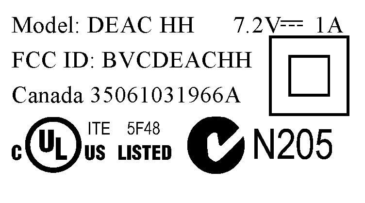
ID Label/Location Info
Regulatory information molded-in graphics area
Operational Description
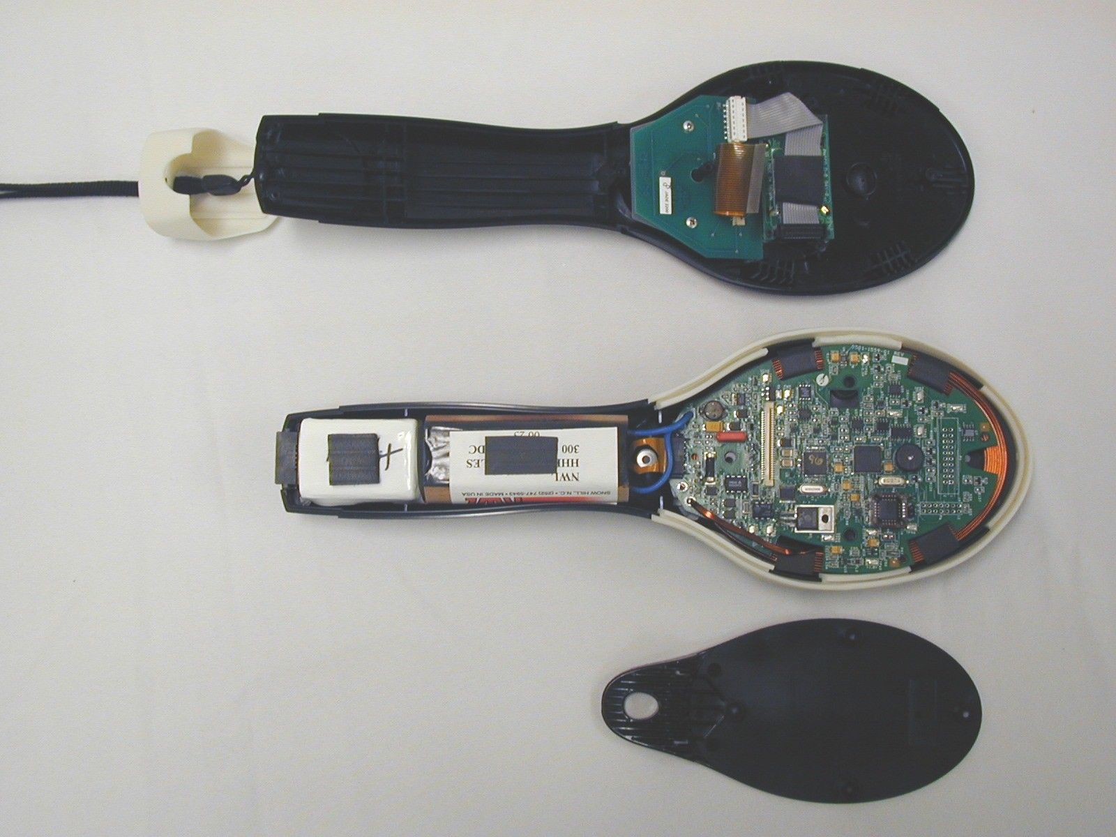
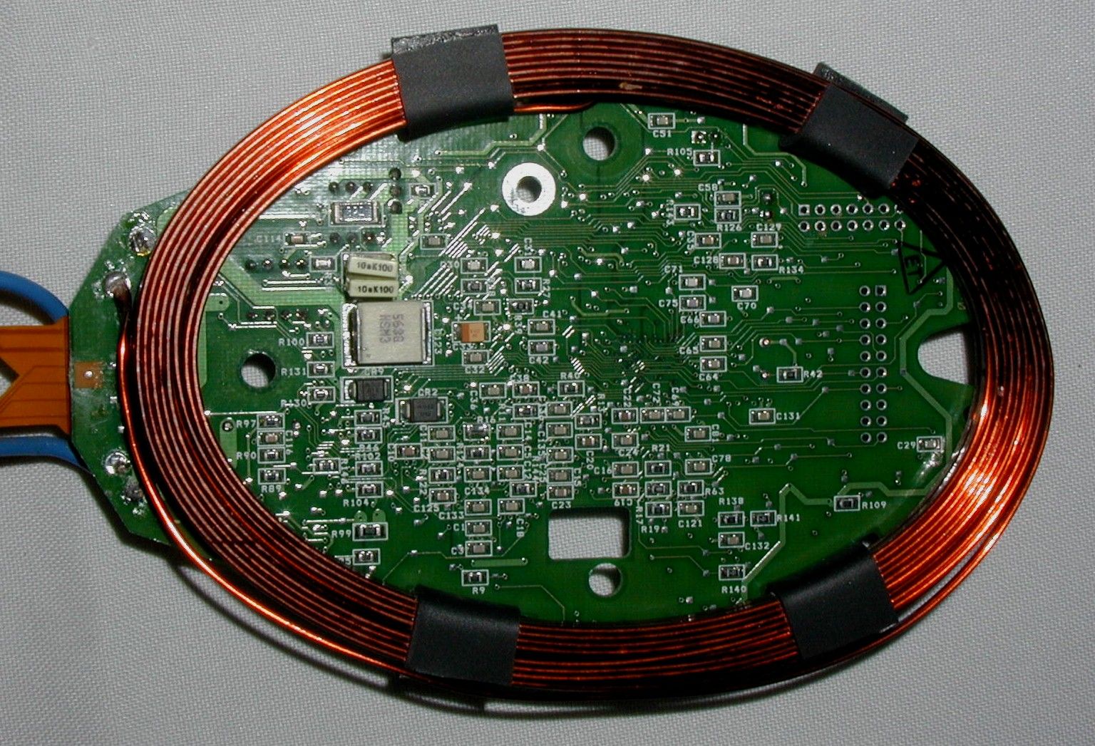
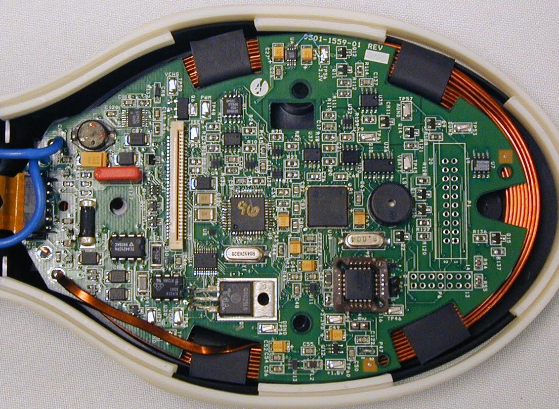
D:\Ready_To_Convert\Doc\109802.DOC Deactivation Products Engineering1 of 1 Hand Held Deactivator General Overview Preliminary Overview The Hand Held Deactivator (HHD) is a self-contained electronic wireless portable proximity deactivator for detection and deactivation of Electronic Article Surveillance (EAS) anti-theft tags. Accompanying the hand held unit is the Base Charging Station (BCS), which serves as a docking station to secure the HHD from theft and charge the battery to full power. Transmitter electronics contained within the Hand Held Deactivator drive an antenna coil to generate a low frequency pulsed magnetic field to excite the tags. Receiver electronics, using the same coil, looks for the unique response from the tag in-between transmit pulses. Once a tag has been detected, the deactivation cycle begins. Control by power electronics, again utilizing the same coil, an extremely low frequency sinusoidal magnetic field (<< 9kHz) of greater amplitude than the excitation (transmit) field is generated. The end of this cycle consists of the signal amplitude decaying at a predetermined rate to create an AC magnetic degaussing field, which deactivates the anti-theft tag. Operator interfaces consist of a nine-button keypad for unit configuration, manual sequence initiation, and security code entry. An audio annunciator and LEDs provide primary unit status information. An eight character by two-line LCD display provides status and mode operation to the operator.
Schematics
E1 AGND1 Switching frequency - 160kHz Feedbackreference(1.25V) VBATT VBATT U30IL4218-X001 1 2 6 5 34 (3V = 150V) Current Sense 0.15V threshold C141220P TP58SMD, LOOP R132 100 TX232 LS1PKM13EPY-4002 12 Q18 IRML2402TR 3 1 2 TX .098 +/- .003 AGND1 C118.1UF C119 1UF TX AUDIO_AC R9310M Battery Q2IRML2402TR 3 1 2 -3.3V (3V = 9V) CR6MBRS140T3 12 + C11747UF25V Vcc Q1 FDC6506P 6 4 5 3 2 1 R9522 AGND1 CR4 MBRS140T3 12 U38LT1783CS6 34 1 62 5 AGND1 Deactivation Coil VBATT +3.3V N=27 flat wire (1mm x 2.6mm)12cm x 8cm ID ellipse Q16 IRML2402TR 3 1 2 R130 10K C114 1UF VBATT AGND1 Q4 IRML2402TR 3 1 2 CR8 MMSZ5236BT17.5V 12 E4 BASE_ID* .098 +/- .003 L122UH 1 2 Battery VBATT C120 .1UF C116 1UF AGND1 SHUTDN_OTB AGND1 AGND1 AGND1 C124 .0022UF BATTERY ReceiverInput AGND1 C136 .1UF TP48SMD, LOOP E2 AGND1 -3.3V R9210M R131 10K UNLOCK J2FLEX, 1X6P 123456 U31 UCC39421PW 46 1516 12357 91011121314 8 PgndVpump COMP Rsel RsenVoutVGrectVGchrgCP Isense Sync/SD RT GND PFM FB Vin R91510 G MT2 MT1 1 2 3 Q3 Q8025L6 R9749.9K R421K R96340K TP45SMD, LOOP POWER AGND1 TP50SMD, LOOP R87 82 AGND1 R9011K AGND1 AGND1 3.7V max RX232 VBATT VBATT R104 0 NOTES FOR THIS PAGE:1. UNLESS OTHERWISE SPECIFIED: RESISTOR VALUES ARE IN OHM +- 5%. RESISTOR POWER RATINGS ARE 1/4W. CAPACITOR VALUES ARE IN MICROFARADS 50V. Lithium Ion Batteries 139uH 75mohm @ 800Hz AGND1 U29 TC4422CPA 241 5678 3 I/P GND1 VDD1 GND2OUT2OUT1VDD2 NC R8922.1K KHZ58 CR7 MURS160T3 1 2 CR10MBRS140T3 12 TP51SMD, LOOP Ec = 2.3J AGND1 AGND1 VBATT R9449.9K ANALOG_IN AGND1 AGND1 Q6 IRFL210 2 1 3 Q7 IRML2402TR 3 1 2 E3 AGND1 C135.1UF AGND1 TP55SMD, LOOP C127 .1UF Vcc AGND1 1/2W Logic Level FETVGS=2.7V AGND1 R88100 R990.1 DX_EN AGND1 AGND1 Q5 IRML2402TR 3 1 2 AGND1 R100 30K R86100 R1292.7 CR5 MURS160T3 1 2 300uF 125V Q17 IRML2402TR 3 1 2 DAMP_BYPASS AGND R146 30K C123 .056UF AGND1 DGND CAPACITOR DGND AGND1 R98205K R1020 S0301-1508-01 1 HANDHELD DEACTIVATOR POWER SUPPLY C 35 Thursday, July 13, 2000 A REL PER ER XXX (PCN#) XXX (DATE) (NAME)R. EASTER(NAME)(NAME)(NAME) (DATE)(DATE)3/5/00(DATE)(DATE) 951 YAMATO ROADBOCA RATON, FLORIDA 33431 TitleSize Document Number Rev Date: Sheet of APPD BY DATE DESCRIPTION PCN NO. LTR DrawnCheckedEngrAppdRelease DATE APPROVALS Sensormatic Electronics Corp. AGND1 AGND1 3.7V max TP52SMD, LOOP CR9MBRS140T3 12
Test Report
FCC ID: BVCDEACHH I. General Information PRODUCT TESTED:Hand Held Deactivator (HHD) FCC ID: BVCDEACHH TEST DATE:July 13-19, 2000 SUMMARY OF RESULTS: 47 CFR 15.207CONDUCTED EMISSIONSPASS 47 CFR 15.209RADIATED EMISSIONSPASS 1.1 Test Methodology Both conducted and radiated emissions testing were performed according to the procedures in ANSI C63.4- 1992, and the requirements of 15.31, 15.33, 15.35, 15.207, and 15.209. Radiated emissions measurements were performed at a distance of 3 meters and the results extrapolated to the distance specified per 15.31 and 15.209. 1.2 Test Facility The shielded room conducted emissions measurement facility is located at Sensormatic Electronics Corporation Headquarters at 951 Yamato Road, Boca Raton, Florida, 33431. The radiated emissions site is located at Sensormatic Electronics Corporation manufacturing location, 6600 Congress Avenue, Boca Raton, Florida 33487. These sites have been found acceptable by and are on file with the FCC per FCC letter 31040/SIT 1300F2. FCC ID: BVCDEACHH 1.3 Test System Description. The HHD system consists of a charging base and a hand held unit. The hand held unit consists of a battery, power supply/transmitter electronics, receive electronics, data processing electronics, deactivation electronics and a multi-turn coil antenna common to transmit, receive and deactivation. The product tested was an engineering prototype built to production drawings. II. Conducted Emissions Conducted emissions data are presented in Section V “Data”, Part A “Conducted Emissions”. The hand held unit was plugged into the base unit and the transmit function was enabled. The battery was discharged prior to initiating the test. The product demonstrated compliance with the requirements of 15.207. The product was tested at 120 V, 60 Hz. III. Radiated Emissions Radiated emissions data are presented in Section V “Data”, Part B “Radiated Emissions”. The product demonstrated compliance with the requirements of 15.209. Radiated emissions measurements were performed at 3 meters. Propagation loss assumed square law roll-off as permitted by the rules; the measurements were extrapolated to 300 meters as required. The hand-held unit was fully charged prior to initiating tests. It was mounted in a vertical position, i.e., the loop antenna was in the vertical plane. Maximum radiation was determined by first assessing symmetry while applying incremental rotation of the turntable. The product exhibited quadrant symmetry. Measurements were taken at radials of 22.5° throughout one quadrant; the measurement antenna was rotated for maximum pickup about the vertical axis of the measurement antenna at each radial. The maximum emission was determined to be with the measurement loop antenna in the vertical polarization, parallel to the radiating loop of the HHD. FCC ID: BVCDEACHH The product was tested and results reported using peak detection. In addition, the product was eligible for extrapolation by calculating the roll off factor as determined by measurements at 2 distances. Although peak detection and square law extrapolation are more severe than required by the rules, measurements using these techniques were sufficient to demonstrate compliance of this product with the FCC rules. FCC ID: BVCDEACHH IV.LIST OF MEASURING EQUIPMENT The equipment used for determining compliance of the HHD system with the requirements of 15.207 and 15.209 is marked with an “X” in the first column of the table below. ModelDescriptionVendorSerial # X ALP -70Loop AntennaElectro Metrics 163 3110BBiconnical AntennaElectro Metrics 1017 3146Log Periodic AntennaEMCO 3909 3825/2Line Imp Stable NetworkEMCO 1562 X 3816/2NMLine Imp Stable NetworkEMCO 9703 1064 6060BFrequency GeneratorGiga-tronics 5850202 FM2000Isotropic Field MonitorAmplifier Research 15171 FP2000Isotropic Field ProbeAmplifier Research 15214 888LevelerAmplifier Research 14998 75A220Low Band AmplifierAmplifier Research 15208 10W1000AHigh Band AmplifierAmplifier Research 15138 PEFT JuniorEFT GeneratorHaefely Trench 083 180-16 PEFT JuniorCapacitive Cable ClampHaefely Trench 083-078-31 NSG435ESD SimulatorSchaffner 1197 NSG431ESD SimulatorSchaffner 1267 X HP8591EMEMC AnalyzerHewlett - Packard 3520A00190 Power SourcePacific Instruments F-2031EM Injection ClampFischer Cust. Comm. 30 FCC-801-M3-16Coupling Decoupling NwkFischer Cust. Comm. 58 FCC-801-M3-16Coupling Decoupling NwkFischer Cust. Comm. 59 F-33-1RF Current Probe Fischer Cust. Comm. 304 EM 7600Transient LimiterElectro-Metrics 187 Roberts AntTunable Dipole SetCompliance Design 003282 Roberts AntTunable Dipole SetCompliance Design 003283 HP8594ESpectrum AnalyzerHewlett Packard 3246A00300 X HP8447F Opt 64Dual PreamplifierHewlett Packard 2805A03473 FCC ID: BVCDEACHH V.Data Part A contains conducted emissions data; Part B contains radiated emissions data. Part A Conducted Emissions Project Name Conducted Emissions Filename HHD_Deac_CondEMI_FCC-B_7-19- 00.doc EUT Name HandHeld Deactivator Serial Number Engineer Larry Canipe Phone Number Date of Test 07/19/2000 3:59:53 PM Test Name FCC Class B Conducted Emissions Reg. Technician C Daoust Co mme nts Line 120vac 60hz; Rev 2 Mesh B; Signal List SignalFreq (MHz)Peak Amp (dBuV) QP Amp (dBuV) Avg Amp (dBuV) FCC Class B Limits (dBuV) Co mme nt s 12.04175046.9443.1327.2248.00 22.50537846.5243.1329.2948.00 30.52105544.2042.9932.5848.00 41.28846044.3642.4627.4248.00 50.60482043.7142.2231.2748.00 61.06300044.4242.1827.7848.00 FCC ID: BVCDEACHH Figure 1. L1 Full Range FCC ID: BVCDEACHH Figure 2. L2 Full Range FCC ID: BVCDEACHH Part BRadiated Emissions Project Name Hand Held Deactivator Filename EUT Name Deac HH Serial Number Engineer Larry Canipe Phone Number Date of Test 7/14/2000 Test Name Radiated Emissions 47CFR15.209 Reg. Technician Steve Krizmanich Proj. Ldr Don Umbdenstock FCC FreqS.A.DetBWAnt FacA>VDCF Correct'd Limit kHzdBuAkHzdBdBdBdBuV/mdBuV/m 5845.1 pk9 11.1 51.5-80 27.732.3/300 11624.2 pk9 4.5 51.5-80 0.226.3/300 17420.2 pk9 0.5 51.5-80 -7.82…
Text truncated - open the document above for the full version.
Contact Information
Applicant
Mark D. Alexis(Manager Regulatory Compliance)
Technical Contact
Sensormatic Electronics CorporationDonald J Umbdenstock
[email protected]561 989 7454
951 Yamato Road · Boca Raton, Florida · United States
Non-Technical Contact
Sensormatic Electronics CorporationDonald J Umbdenstock
[email protected]561 989 7454
Test Firm
Sensormatic Electronics CorporationWilliam Elliott
Technical Specifications
| # | Rule Parts | Frequency Range | Power Output |
|---|---|---|---|
| 1 | 15C | 0.058 MHz - 0.058 MHz | - |
Other Applications from Tyco Safety Products/Sensormatic

BVCIDX5000
Jun 23, 2026UHF RFID Reader
Equipment Class
DSS - Part 15 Spread Spectrum TransmitterBVCAMS1137H
Dec 22, 2025Anti Theft System - Electronic Asset Security
Equipment Class
FAP - Part 15 Anti-Pilferage DeviceBVCAMB9012
Sep 10, 2024Label Deactivator Controller
Equipment Class
DCD - Part 15 Low Power Transmitter Below 1705 kHz
BVC-4000-PI26
Sep 24, 2015RM2L-4000-P126, RM2-4000-P126
Equipment Class
DXX - Part 15 Low Power Communication Device Transmitter
BVCAMS90604
May 20, 2014Anti-pilferage Device
Equipment Class
FAP - Part 15 Anti-Pilferage Device