BVCDEACLCDAnti Theft Auxiliary Device
Tyco Safety Products/Sensormatic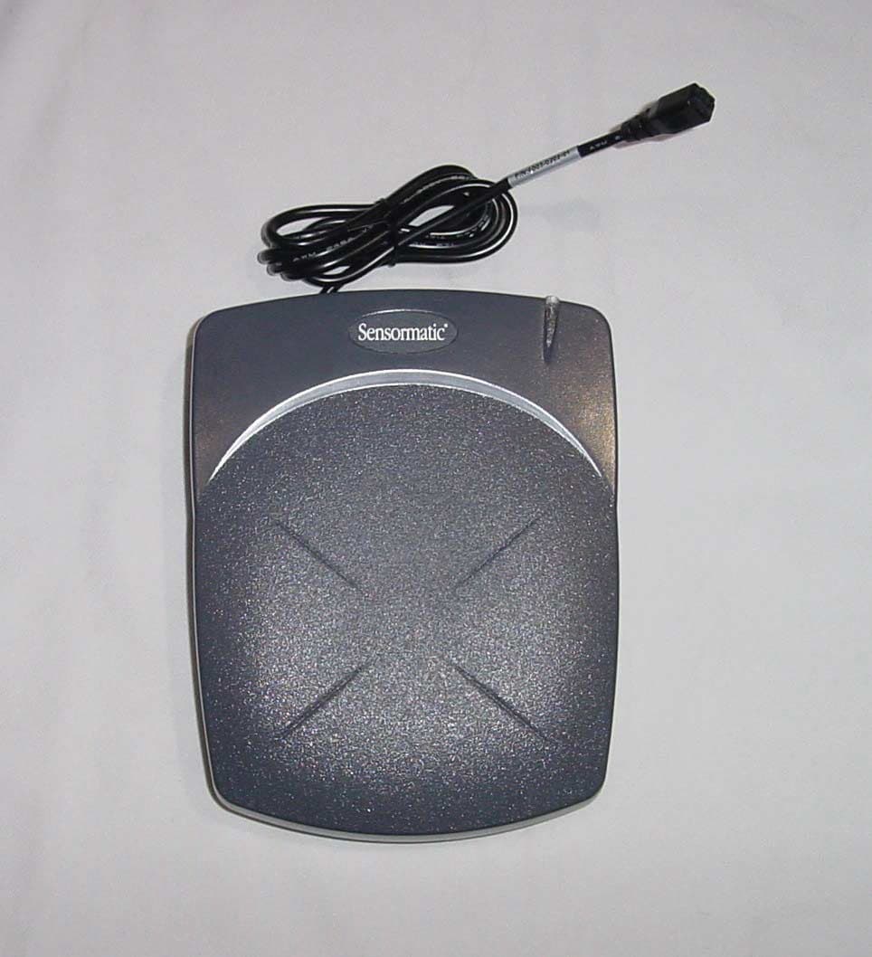
Click to zoom
Application Details
- Equipment Class
- FAP - Part 15 Anti-Pilferage Device
- Date of Grant
- Dec 22, 2002
- Application Purpose
- Original Equipment
- Date of Application
- Dec 22, 2002
- Equipment Note
- Anti Theft Auxiliary Device
- Frequency Range
- 0.05800000 - 0.05800000
- Country
- United States
Documents & Files
Document Text
Text extracted from the exhibit documents filed with the FCC. Open a document above to read the original.
Users Manual
ZBAMB2010T TABLETOP DEACTIVATOR INSTALLATION GUIDE (8200-0185-01, REV. A) 1 of 3 ZBAMB2010T Tabletop Deactivator Installation Guide The AMB-2010 tabletop deactivator consists of the deactivator unit and a class 2 external power supply that plugs into an ac outlet. The power LED glows green when power is applied. The deactivator deactivates UltraStrip II and III security labels rubbed and swirled on its surface. The deactivate field is 10cm (4 in.) square and 7.5cm (3 in.) high. Deactivation is indicated by the power LED pulsing orange and a long beep. WARNING: Do not deactivate labels on audio or videotapes. The deactivate field is not magnetic media safe. The deactivator is intended to be installed “as is” without adjustments. If adjustments are necessary, a laptop computer containing special configuration software can be connected to a jack at the rear of the deactivator. Please observe the following safeguards before you begin installation. WARNING: Hazardous areas. DO NOT install the deactivator where highly combustible or explosive products are stored or used. WARNING: RISK OF ELECTRIC SHOCK! Deactivator has no user-serviceable parts! DO NOT attempt to open the deactivator. Power Cord. The cord cannot interfere with the operation of cash drawers, conveyor belts, or with the operation, maintenance or removal of equipment. © Sensormatic 2002 If you need assistance... Call 1-800-241-6678 (Sensormatic / ADT Customer Response Center). Cleaning the Deactivator Clean exterior surface using a soft cloth moistened with warm, soapy water. Dry thoroughly. DO NOT use solvents or scouring cleanser. Deactivation Status Indications Status LED Tone Power On Sequence Flashing Green (for 10 seconds) Short Beep Ready Green Deactivate Pulsing Orange Long Beep Transmit Off Flashing Green Fault Condition Red Hard Tag Present Continuous Short Beep Install Kit Required Install Kit 0352-0101-01 Deactivator Assy. 1 0303-0038-01 Template, Cutout 1 8000-2699-02 Velcro, Hook, w/Adhesive .5ft 3200-0358-01 Velcro, Loop, w/Adhesive .5ft 3200-0358-02 Cable Tie, 5-1/2"L x 16"W, Nylon 3 6009-0001 Mount, Adhesive Backed, 1-1/8 sq. 3 6009-0003 Clamp, Cable, Nylon, .313D, .172MTG 2 6010-0035-10 Screw, Self-Tapping, 3.5x16 PHP 2 5810-3051-120 Label, Keep Magnetic Media Away 1 2402-1301-01 Pad, Alcohol 2 1600-0033 Tools Required § Power drill and drill bits § Phillips screwdriver § Hand vacuum and broom. Proper Placement § DO NOT install the deactivator over a metal surface. Deactivator fields interact with metal causing deactivator performance to degrade. § The field from the deactivator can interact with certain POS equipment. Avoid placing the deactivator too close to POS equipment. ! ! ZBAMB2010T TABLETOP DEACTIVATOR INSTALLATION GUIDE (8200-0185-01, REV. A) 2 of 3 Installation Positioning the deactivator so the LED window faces away from the sales associate: 1. Mount the deactivator to the countertop. Using a ZPCM mounting bracket (optional): See instructions supplied with bracket. Using hook and loop material: a. Mate hook and loop material, then cut hook and loop material into two strips. b. Remove the liner from the hook side of each strip, then fasten a strip to the flat area on the bottom front and rear edges of the deactivator. c. Place the deactivator in the desired location and press down. Using M5 machine screws: a. Place the template supplied in the desired mounting location and use it to drill four holes for M5 machine screws. b. Select the appropriate length for the screws. Screw length should be 8mm (.31 in.) plus the counter thickness. c. From the underside of the countertop, insert the four machine screws, mate them with the mounting holes in the bottom of the deactivator, and tighten from below. 2. Secure the power cable. Using cable ties (not shown): a. Remove the liner from the adhesive- backed mount and run a tie through the hole in the mount and around the cable. b. Fasten the cable tie securely around the cable and remove excess. Using the cable clamp: a. Place the clamp around the cable near the antenna. b. Secure the clamp in place using a screw. 3. Connect the deactivator to the power supply and plug the power supply into an ac outlet. The deactivator will produce a brief tone at power up. Cable Clamp, if used. Hook and Loop Material, if used. Holes for M5 Machine Screws (4), if used. ZBAMB2010T TABLETOP DEACTIVATOR INSTALLATION GUIDE (8200-0185-01, REV. A) 3 of 3 Optional Adjustments To be determined. Specifications Power Supply Input voltage ..................... 100–240 Vac, 50/60 Hz AC line current .................. 1 Arms (max.) Deactivator Input voltage ..................... 18 Vdc Auto synchronization......... Optional Tone volume ..................... Adjustable, Off Operating temperature ...... 0° to 40°C Humidity ............................ 0 to 90% non-condensing Weight (deactivator) .......... 0.95kg (2.1 lbs) Weight (power supply) ...... 0.28kg (0.6 lbs) Declarations Regulatory Compliance EMC ....................................... 47 CFR Part 15 RSS 210 EN 300330 EN 301489 EMF........................................ VDE 0848 Safety ..................................... UL60950 EN 60 950 CE Mark FCC COMPLIANCE: This equipment complies with Part 15 of the FCC rules for intentional radiators and Class A digital devices when installed and used in accordance with the instruction manual. Following these rules provides reasonable protection against harmful interference from equipment operated in a commercial area. This equipment should not be installed in a residential area as it can radiate radio frequency energy that could interfere with radio communications, a situation the user would have to fix at their own expense. EQUIPMENT MODIFICATION CAUTION: Equipment changes or modifications not expressly approved by Sensormatic Electronics Corporation, the party responsible for FCC compliance, could void the user's authority to operate the equipment and could create a hazardous condition.…
Text truncated - open the document above for the full version.
Cover Letter(s)
Sensormatic Electronics Corporation 6600 Congress Avenue, Boca Raton, FL 33487 Telephone (561) 912-6000 FAX (561) 912-6787 December 17, 2002 Timco Engineering, Inc. 849 N.W. State Road 45 P.O. Box 370 Newberry, Florida 32669 USA Re: Request for withholding from public disclosure proprietary information submitted pursuant to an application for certification for a low power transmitter. FCC ID: BVCDEACLCD Dear Sir or Madam: Sensormatic Electronics Corporation requests certain materials submitted with this application for certification of device FCC ID: BVCDEACLCD be withheld from public disclosure. This request is made under the provision of 47 CFR 0.457 (d) and 5 USC 552(b)(4) Freedom of Information Act, Trade Secrets. The items for which confidentiality is requested include the Operational Description, Block Diagram and Schematic Diagrams. This information contains proprietary information (trade secrets) regarding the circuit operation and capabilities (specific values of components, circuit design details and system architecture) that are the result of our extensive investment in research and development. Without the disclosed information, competitive organizations would take considerable more time to assess and develop a workable competitive product. As a result, we believe that disclosure of these company-guarded materials would compromise our leading position in this market. We therefore formally request that the materials identified “Confidential” be kept strictly confidential and not made available for inspections by any other party, except on a need to know basis for the sole purpose of the certification process. Sincerely, Donald J. Umbdenstock Sr. Principal Engineer, Compliance Engineering
External Photos
System Components Controller
ID Label/Location Info
2412-0226-05 Rev C N205 NRTL Model: AMB-2010 MFD:7-02 P/N: 0101-0040-01 REV : A SERIAL NO: SECA0117012345 RATING: 18V 1.7A MADE IN PUERTO RICO BARCODE FCC ID: BVCDEACLCD THIS DEVICE COMPLIES WITH PART 15 OF THE FCC RULES. OPERATION IS SUBJECT TO THE FOLLOWING TWO CONDITIONS: (1) THIS DEVICE MAY NOT CAUSE HARMFUL INTERFERENCE, AND (2) THIS DEVICE MUST ACCEPT ANY INTERFERENCE RECEIVED, INCLUDING INTERFERENCE THAT MAY CAUSE UNDESIRED OPERATION. IC: 3506A- DEACLCD â
Internal Photos
Controller, Top Cover Off Controller, Bottom Cover Off Printed Circuit Card Assembly, Top View Printed Circuit Card Assembly, Bottom View
Test Report
FCC ID: BVCDEACLCD IC: 3506A – DEACLCD 1 Appendix II Test Report Cover Sheet COMPANY NUMBER: 3506A MODEL NUMBER: AMB-2010 MANUFACTURER: Sensormatic Electronics Corporation TESTED TO RADIO STANDARD SPECIFICATION NO. : RSS 210 OPEN AREA TEST SITE INDUSTRY CANADA NUMBER: 3506 FREQUENCY RANGE (or fixed frequency): 58 R.F. POWER IN WATTS: na FIELD STRENGTH (at what distance): -23 dBuV/m @300 m OCCUPIED BANDWIDTH (99% BW): 5 kHz TYPE OF MODULATION: Pulse EMISSION DESIGNATOR (TRC-43): 5k00P0N TRANSMITTER SPURIOUS (worst case): -25 dBuV/m @ 30 m RECEIVER SPURIOUS (worst case): na; transmitter on continuously ATTESTATION: I attest that the testing was performed or supervised by me; that the test measurements were made in accordance with the above mentioned departmental standard(s), and that the radio equipment identified in this application has been subject to all the applicable test conditions specified in the departmental standards and all of the requirements of the standard have been met. Signature: Date: December 13, 2002 NAME AND TITLE (Please print or Type): Donald J. Umbdenstock Sr. Principal Engineer, Compliance Engineering . Note : This form must be completed and provided with the submission. FCC ID: BVCDEACLCD IC: 3506A – DEACLCD 2 COMPANY Sensormatic Electronics Corp. 6600 Congress Ave Boca Raton, Florida PRODUCT TESTED AMB-2010 FCC ID: BVCDEACLCD IC: 3506A-DEACLCD FCC RULES 15.207, 15.209 IC SPECIFICATIONS RSS 210 TEST DATE December 2 – December 13, 2002 SUBMITTED BY Donald J. Umbdenstock FCC ID: BVCDEACLCD IC: 3506A – DEACLCD 3 INDEX I. SUMMARY OF RESULTS 4 II. GENERAL INFORMATION 4 Test Methodology 4 Test Facility 4 System Description 5 15.203 Compliance 5 III. CONDUCTED EMISSIONS TESTING, 47 CFR 15.207 5 IV. RADIATED EMISSIONS TESTING, 47 CFR 15.209 5 V. OCCUPIED BANDWIDTH, RSS 210, Clause 5.9.1 6 VI. RF EXPOSURE 6 VII. LIST OF MEASUREMENT EQUIPMENT 7 VII. DATA Part A – Conducted Emissions 8 Part B – Radiated Emissions 10 Part C – 20 dB Bandwidth 11 FCC ID: BVCDEACLCD IC: 3506A – DEACLCD 4 I. Summary of Results 47 CFR 15.207 CONDUCTED EMISSIONS COMPLIES 47 CFR 15.209 RADIATED EMISSIONS COMPLIES RSS 210: 5.9.1 OCCUPIED BANDWIDTH PROVIDED II. General Information 1.1 Test Methodology Both conducted and radiated emissions testing were performed according to the procedures in ANSI C63.4-1992, and the requirements of 15.31, 15.33, 15.35, 15.207, and 15.209. Radiated emissions measurements below 30 MHz were performed at a distance of 3 meters and the results extrapolated to the distance specified per 15.31 and 15.209 invoking the 2 point extrapolation method. 1.2 Test Facility Measurements per 15.207 and 15.209 were performed at Sensormatic Electronics Corporation. The shielded room conducted emissions measurement facility and the radiated emissions Open Area Test Site are located at Sensormatic Electronics Corporation Headquarters at 6600 Congress Avenue, Boca Raton, Florida 33487. These sites have been found acceptable by and are on file with the FCC per FCC Registration Number 90925, and Industry Canada per file number IC 3506. FCC ID: BVCDEACLCD IC: 3506A – DEACLCD 5 1.3 Test System Description. The device is an anti-theft system auxiliary device whose purpose is to detect and deactivate anti-theft labels. The device consists of 2 modules – an external power supply and a controller. The controller houses a transmitter, 2 receivers, a deactivator, and control electronics. When an anti-theft label is brought in proximity of the loop antenna of the controller, the transmitter excites the label. The receiver detects the presence of the label and enables the deactivator. The other receiver operates as a frequency hopping 900 MHz device. It receives 60 Hz zero-crossing information from a transmitter generating a reference signal. The reference signal is used to synchronize the controller’s transmitter to other transmitters in the area so that transmitters are not interfering with the receive windows of various systems in the vicinity. The product tested was a pre-production unit built to production drawings. 15.203 . The antenna is an internal integral antenna, therefore the antenna is compliant with the requirements of this clause. III. Conducted Emissions 15.207. Conducted emissions data are presented in Section VIII “Data”, Part A, Conducted Emissions. The product demonstrated compliance with the requirements. The product was tested at 120 V, 60 Hz. IV. Radiated Emissions 15.209. Radiated emissions data for this product are presented in Section VIII “Data”, Part B, Radiated Emissions. The product demonstrated compliance with the requirements. Radiated emissions measurements were performed at 3 meters. Propagation loss was determined by extrapolating the results to 300 meters as per 15.31(f)(2), using the 2 point extrapolation method. FCC ID: BVCDEACLCD IC: 3506A – DEACLCD 6 Maximum radiation was determined by first assessing symmetry while applying incremental rotation of the product. The product exhibited quadrant symmetry. Measurements were taken at radials of 22.5° throughout one quadrant. The measurement antenna was rotated for maximum pickup about the vertical and horizontal axis of the measurement antenna at the radial of the EUT with the maximum emission. The maximum emission was determined to be with the measurement loop antenna in the vertical polarization, parallel to the plane of the transmit loop antenna. The product was tested at input voltages to the power supply ranging from 102 – 138 V, 60. See Section VIII, Part B. V. Occupied Bandwidth RSS 210:5.9.1. The 20 dB bandwidth measurements for this product are presented in Section VII “Data”, Part C, Occupied Bandwidth. A bandwidth requirement was not specified for 58 kHz products, so the default 20 dB bandwidth was measured. The HP 8591EM spectrum analyzer cannot measure a bandwidth over 1.8 kHz in quasi-peak detection mode, so the bandwidth was measured in peak detection mode, providing a worst case occupied bandwidth. FCC I…
Text truncated - open the document above for the full version.
Test Setup Photos
Set Up Photos Radiated Emissions Conducted Emissions
Contact Information
Applicant
Mark D. Alexis(Manager Regulatory Compliance)
Test Firm
Sensormatic Electronics CorporationWilliam Elliott
Technical Specifications
| # | Rule Parts | Frequency Range | Power Output |
|---|---|---|---|
| 1 | 15C | 0.058 MHz - 0.058 MHz | - |
Other Applications from Tyco Safety Products/Sensormatic

BVCIDX5000
Jun 23, 2026UHF RFID Reader
Equipment Class
DSS - Part 15 Spread Spectrum TransmitterBVCAMS1137H
Dec 22, 2025Anti Theft System - Electronic Asset Security
Equipment Class
FAP - Part 15 Anti-Pilferage DeviceBVCAMB9012
Sep 10, 2024Label Deactivator Controller
Equipment Class
DCD - Part 15 Low Power Transmitter Below 1705 kHz
BVC-4000-PI26
Sep 24, 2015RM2L-4000-P126, RM2-4000-P126
Equipment Class
DXX - Part 15 Low Power Communication Device Transmitter
BVCAMS90604
May 20, 2014Anti-pilferage Device
Equipment Class
FAP - Part 15 Anti-Pilferage Device