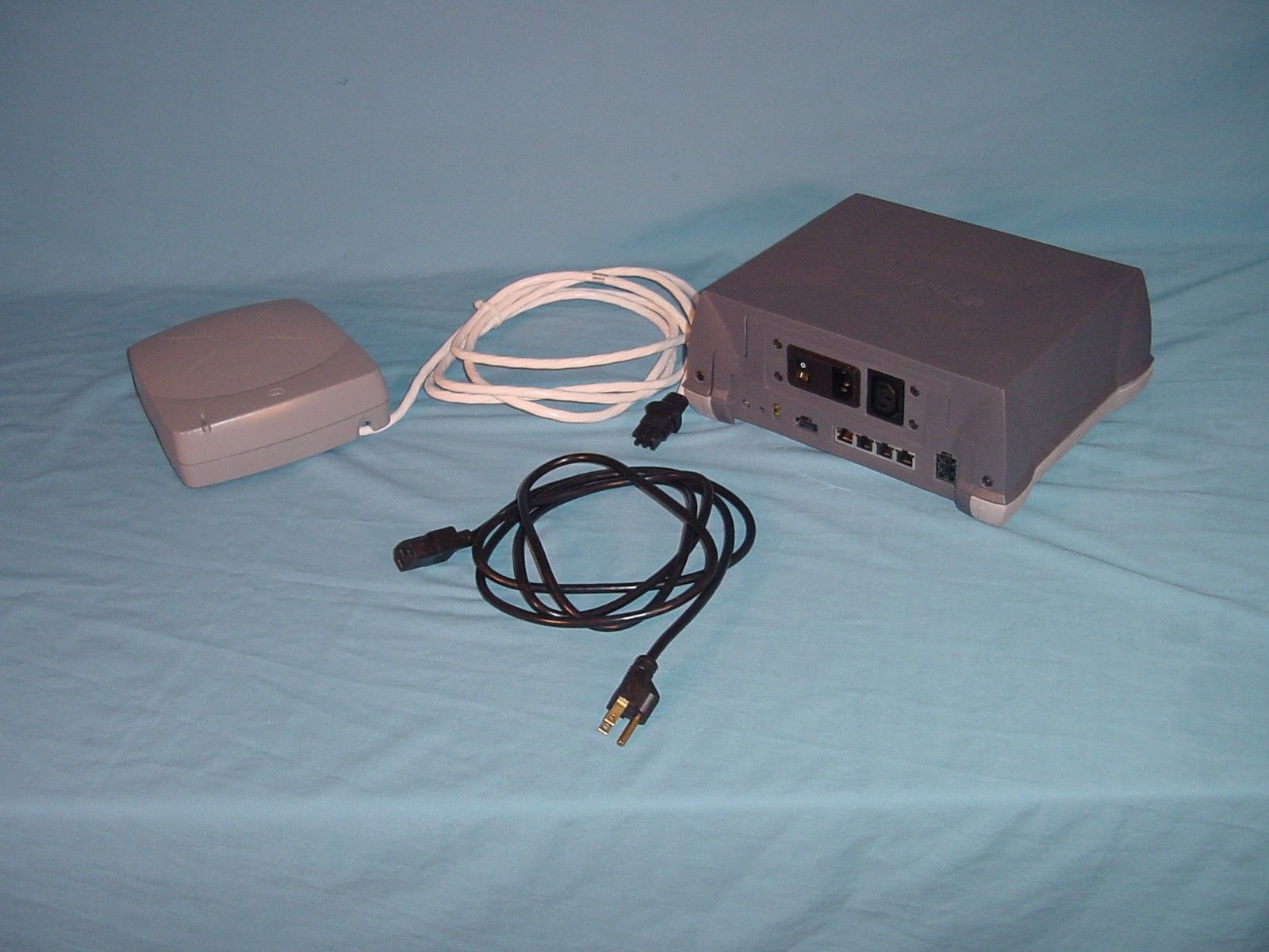
BVCDEACMERAnti-Theft Device
Tyco Safety Products/Sensormatic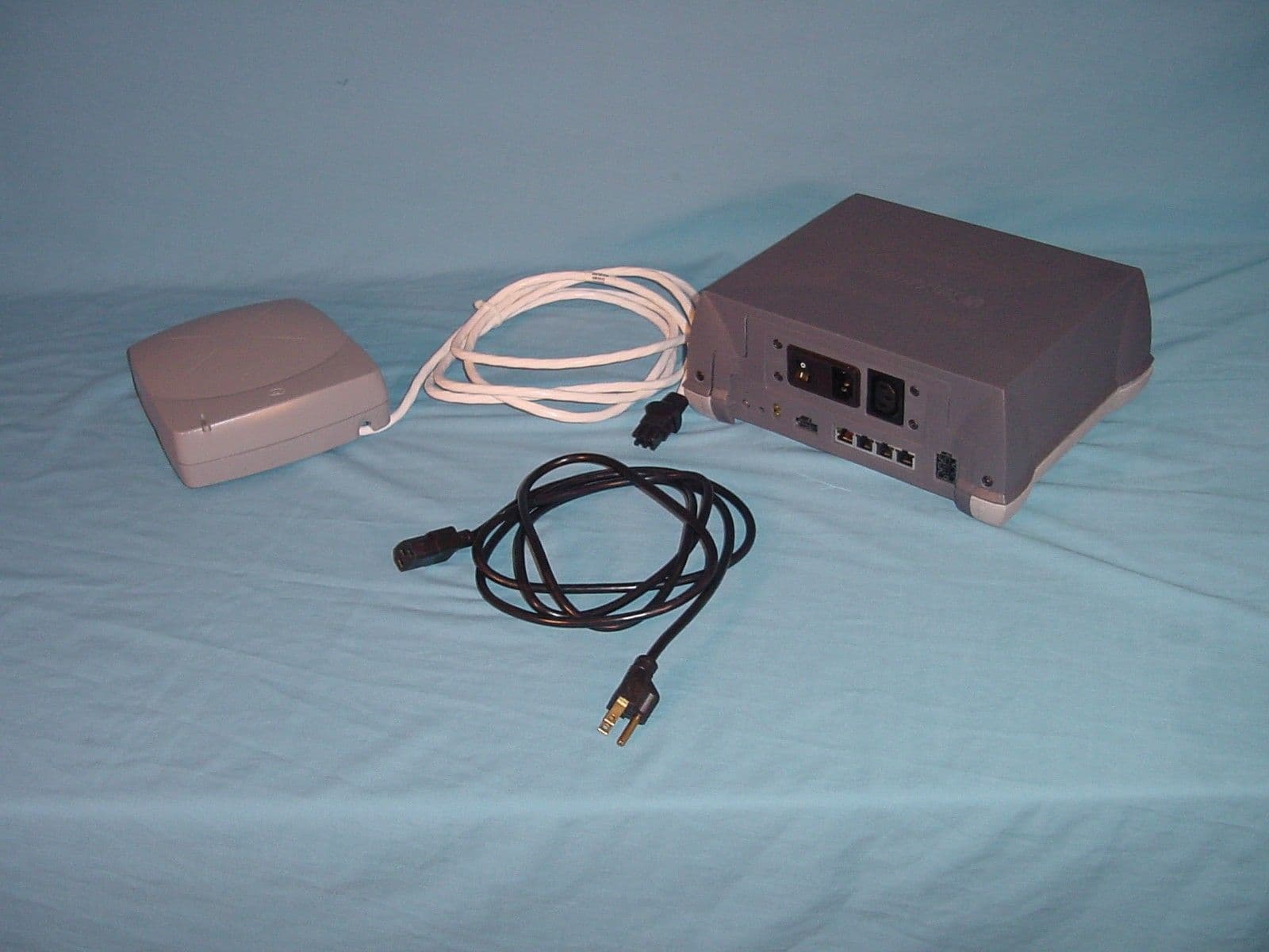
Click to zoom
Application Details
- Equipment Class
- FAP - Part 15 Anti-Pilferage Device
- Date of Grant
- Mar 24, 2002
- Application Purpose
- Original Equipment
- Date of Application
- Mar 24, 2002
- Equipment Note
- Anti-Theft Device
- Frequency Range
- 0.05800000 - 0.05800000
- Country
- United States
Documents & Files
Document Text
Text extracted from the exhibit documents filed with the FCC. Open a document above to read the original.
Users Manual
Company Confidential SCANMAX PRO INSTALLATION AND SETUP GUIDE (8200-0054-01, REV. 02) 1 of 5 ZBSMPRO ZBSMPROZBSMPRO ZBSMPRO ScanMax™ Pro ScanMax™ Pro ScanMax™ Pro ScanMax™ Pro Controller ControllerController Controller Installation and Setup Guide Installation and Setup GuideInstallation and Setup Guide Installation and Setup Guide ScanMax Antennas Used with ScanMax Antennas Used with ScanMax Antennas Used with ScanMax Antennas Used with this Controller this Controllerthis Controller this Controller ! PowerPad (ZBSMPPP) ! Slim Pad (ZBSMPSP) ! CompactPad Tabletop Version (ZBSMPCP) ! CompactPad Flush Mount Version (ZBSMPCP-F) ! Low Profile Pad (ZBSMPLP) ! Integrated Pad (ZBSMPIP) © Sensormatic 2002 Equipment Required Equipment RequiredEquipment Required Equipment Required • Controller • Laptop with minimum Windows 98 SE • Standard CE RS232 Ultra•Max programming cable • Hard Tag • Four DR LE labels minimum Installation InstallationInstallation Installation The controller can be mounted three ways: ! On the countertop ! To the underside of the countertop ! To the sidewall of the counter. Warning! If mounting the controller to the sidewall of a counter, its cable connectors cannot face up. The controller can be mounted, out-of-the-box, to the countertop. If mounted to the underside of the countertop or to the sidewall of the counter, a mounting bracket is required. This bracket contains key slots for easy mounting. Detailed mounting instructions are supplied with the bracket. Company Confidential SCANMAX PRO INSTALLATION AND SETUP GUIDE (8200-0054-01, REV. 02) 2 of 5 Setup SetupSetup Setup 1. If supplied, plug the remote cable into the “remote” controller port. 2. Plug in the antenna cable. 3. Plug the AC cord into the input male jack. 4. Turn on the AC power. The rocker switch should be ‘green’ and the status indicator may blink orange until the controller auto- synchronizes. When synchronizing is complete, the status indicator should be solid green. Auto synchronization can take up to ten seconds. Note: If the status indicator is blinking green, then either the deactivation or transmit function is disabled. If the indicator is alternating red/yellow or is solid red, then there is no high voltage available for deactivation. In either case, contact ADT for advice. The complete list of status indications is shown opposite. Controller Status Indicators Controller Status IndicatorsController Status Indicators Controller Status Indicators Status Indicator on Controller (Note: Red color may appear orange.) Solid Green Unit ready. Blinking Green Transmit disabled by key switch or configurator. Blinking Yellow Controller is in auto- sync. Alternating Red/Yellow The high voltage circuit is not working. Solid Red +25V or sync fault. Mode Indicator on Controller (Use the PROG Button to cycle through the selections below.) Bottom LED On The controller is set for use with an SR label. Bottom LED Off The controller is set for use with a DR label. Top LED On The controller is set for Mag-Safe operation. Top LED Off The controller is set for routine operation. Both LEDs Blink Antenna EEPROM fault. Status Indicators on Remote Alarm Module (if used) Green On, Red Off Unit ready. Blinking Green Transmit disabled by key switch or configurator. Green On, Yellow Blinks Controller is in auto- sync. Green On, Red Flashing Every 250 ms The high voltage circuit is not working. One Beep The controller attempted to deactivate a label. Continuous beep until a hard tag is removed from the field. The controller is in HT test mode. Remote Port Antenna Port AC Power Cord AC Power Switch Status Indicator Program Button Mode Indicator Company Confidential SCANMAX PRO INSTALLATION AND SETUP GUIDE (8200-0054-01, REV. 02) 3 of 5 Advanced Setup and Advanced Setup and Advanced Setup and Advanced Setup and Adapter Configuration Adapter ConfigurationAdapter Configuration Adapter Configuration 1. Plug in the programming cable into the service port of the controller. 2. Start the ScanMax Pro configurator by clicking on the icon. 3. Verify settings as follows for your antenna type. Do not change settings at this time. Default Settings Antenna Tx Power Threshold Low Profile Pad Med 8 (+1)" 20 (+2.5) cm PowerPad Med 7 (+1.5)” 17.5 (+3.75) cm SlimPad Med 6 (+1.5)" 15 (+3.75) cm ScanMax IP Med 6 (+1.5)" 15 (+3.75) cm CompactPad Med 6 (+1)" 15 (+2.5) cm 4. Use the threshold setting to adjust the detection height for the checkout environment. Use the detection compensation slide bar to compensate for special mounting such as metal countertops. 5. Using the EXIT button on the configurator, exit the configurator. If false deactivating occurs... If false deactivating occurs... If false deactivating occurs... If false deactivating occurs... If false deactivating occurs, the configuration default values need to be modified as follows: a. Plug in the programming cable into the Service port of the controller. b. Start the ScanMax Pro configurator by clicking on the icon. c. Click on the RESYNC button. If false deactivation discontinues, go back to step 4; otherwise, continue. d. Ensuring no label/tag is close to the antenna, reduce Tx POWER one level at a time until the system does not false deactivate (firing without a label/tag present). Write this level down. e. Set the Tx POWER level one step higher. Note: Maximum detection and deactivation height may be reduced compared with that listed in the table due to ambient noise and mounting locations. Note the new heights. f. If these steps fail to stop false deactivation, contact Service Planning. Exit Button Detection Compensation Tx Power Company Confidential SCANMAX PRO INSTALLATION AND SETUP GUIDE (8200-0054-01, REV. 02) 4 of 5 Specifications SpecificationsSpecifications Specifications Electrical ElectricalElectrical Electrical Primary input.......................... 100-120/200-240 Vac 50-60 Hz ±5% 1.4 Arms maximum Environmental EnvironmentalEnvironmental Environmental Operating temperature ....…
Text truncated - open the document above for the full version.
Cover Letter(s)
Sensormatic Electronics Corporation 951 Yamato Road, Boca Raton, FL 33431- 0700 Telephone (561) 989-7000 FAX (561) 989-7548 March 20, 2002 Timco Engineering, Inc. 849 N.W. State Road 45 P.O. Box 370 Newberry, Florida 32669 USA Re: Request for withholding from public disclosure proprietary information submitted pursuant to an application for certification for a low power transmitter. FCC ID: BVCDEACMER Dear Sir or Madam: Sensormatic Electronics Corporation requests certain materials submitted with this application for certification of device FCC ID: BVCDEACMER be withheld from public disclosure. This request is made under the provision of 47 CFR 0.457 (d) and 5 USC 552(b)(4) Freedom of Information Act, Trade Secrets. The items for which confidentiality is requested include the Operational Description, Block Diagram and Schematic Diagrams. This information contains proprietary information (trade secrets) regarding the circuit operation and capabilities (specific values of components, circuit design details and system architecture) which are the result of our extensive investment in research and development. Without the disclosed information, competitive organizations would take considerable more time to assess and develop a workable competitive product. As a result, we believe that disclosure of these company-guarded materials would compromise our leading position in this market. We therefore formally request that the materials identified “Confidential” be kept strictly confidential and not made available for inspections by any other party, except on a need to know basis for the sole purpose of the certification process. Sincerely, Donald J. Umbdenstock Sr. Principal Engineer, Compliance Engineering
ID Label/Location Info
PRODUCT CODE: ZBSMPRO REG ID: DEAC MER-PP MFD:3-02 P/N: 0400-1413-01 REV : A SERIAL NO: SECA0117012345 RATING: 100-120/220-240V~ 50-60Hz 1.0A + 7A outlet FCC ID: BVCDEACMER THIS DEVICE COMPLIES WITH PART 15 OF THE FCC RULES. OPERATION IS SUBJECT TO THE FOLLOWING TWO CONDITIONS: (1) THIS DEVICE MAY NOT CAUSE HARMFUL INTERFERENCE, AND (2) THIS DEVICE MUST ACCEPT ANY INTERFERENCE RECEIVED, INCLUDING INTERFERENCE THAT MAY CAUSE UNDESIRED OPERATION. IC: 3506A-DEACMER ITE 5F48 MADE IN PUERTO RICO N205 BARCODE
ID Label/Location Info
Regulatory Label Location (bottom, front)
Internal Photos
PAD (ANTENNA) ELECTRONICS MODULE Powdered iron core 1 of 2 antenna windings Capacitor, Deactivation Power Entry Filter ELECTRONICS MODULE, COVER AND FILTER REMOVED PRINTED CIRCUIT BOARD ASSEMBLY, TOP VIEW PRINTED CIRCUIT BOARD ASSEMBLY, BOTTOM VIEW
Test Report
FCC ID: BVCDEACMER IC: 3506A DEACMER 1 Appendix III Test Report Cover Sheet/Performance Test Data MODEL NUMBER: DEAC MER MANUFACTURER: Sensormatic Electronics Corp. TESTED TO RADIO STANDARD SPECIFICATION NO. : RSS 210 OPEN AREA TEST SITE INDUSTRY CANADA NUMBER: IC 3506 FREQUENCY RANGE (or fixed frequency): 58 KhZ R.F. POWER IN WATTS: n/a FIELD STRENGTH (at what distance): 16 dBuV/m@300m OCCUPIED BANDWIDTH (99% BW): 10.7kHz TYPE OF MODULATION: pulse EMISSION DESIGNATOR (TRC-43): 10K7PON TRANSMITTER SPURIOUS (worst case): -6.8dBuV/m@300m RECEIVER SPURIOUS (worst case): see transmitter ATTESTATION: DECLARATION OF COMPLIANCE : I declare that the testing was performed or supervised by me; that the test measurements were made in accordance with the above mentioned department standard(s), and that the radio apparatus identified in this application has been subject to all the applicable test conditions specified in the departmental standards and all of the requirements of the standard have been met. Signature: Date: March 11, 2002 NAME AND TITLE (Please print or Type): Donald J. Umbdenstock Senior Principal Engineer, Compliance Engineering Note : This form must be completed and provided with the submission. FCC ID: BVCDEACMER IC: 3506A DEACMER 2 COMPANY Sensormatic Electronics Corp. 6600 Congress Ave Boca Raton, Florida PRODUCT TESTED ScanMax Pro FCC ID: BVCDEACMER IC: 3506A-DEACMER FCC RULES 15.207, 15.209 IC SPECIFICATIONS RSS 210 TEST DATE January 22, February 25, 2002 SUBMITTED BY Donald J. Umbdenstock FCC ID: BVCDEACMER IC: 3506A DEACMER 3 INDEX I. SUMMARY OF RESULTS 4 II. GENERAL INFORMATION 4 Test Methodology 4 Test Facility 4 System Description 5 15.203 Compliance 5 III. CONDUCTED EMISSIONS TESTING, 47 CFR 15.207 5 IV. RADIATED EMISSIONS TESTING, 47 CFR 15.209 6 V. OCCUPIED BANDWIDTH, RSS 210, Clause 5.9.1 6 VI. LIST OF MEASUREMENT EQUIPMENT 7 VII. DATA 8 Part A – Conducted Emissions 8 Part B – Radiated Emissions 9 Part C – 20 dB Bandwidth 10 FCC ID: BVCDEACMER IC: 3506A DEACMER 4 I. Summary of Results 47 CFR 15.207 CONDUCTED EMISSIONS COMPLIES 47 CFR 15.209 RADIATED EMISSIONS COMPLIES RSS 210: 5.9.1 OCCUPIED BANDWIDTH PROVIDED II. General Information 1.1 Test Methodology Both conducted and radiated emissions testing were performed according to the procedures in ANSI C63.4-1992, and the requirements of 15.31, 15.33, 15.35, 15.207, and 15.209. Radiated emissions measurements below 30 MHz were performed at a distance of 5 meters and the results extrapolated to the distance specified per 15.31 and 15.209. 1.2 Test Facility Measurements per 15.207 and 15.209 were performed at Sensormatic Electronics Corporation. The shielded room conducted emissions measurement facility is located at Sensormatic Electronics Corporation Headquarters at 951 Yamato Road, Boca Raton, Florida, 33431. The radiated emissions Open Area Test Site is located at Sensormatic Electronics Corporation manufacturing location, 6600 Congress Avenue, Boca Raton, Florida 33487. These sites have been found acceptable by and are on file with the FCC per FCC Registration Number 90925, and Industry Canada per file number IC 3506. FCC ID: BVCDEACMER IC: 3506A DEACMER 5 1.3 Test System Description. The system consists of an electronics module that houses the transmitter, receiver, deactivator and processor circuitry. The antenna is contained in a plastic enclosure in the shape of a thick pad. It consists of a multi-turn loop antenna wound on an iron core. The product tested was a pre-production unit built to production drawings. 15.203 . The antenna is contained internally to the pad assembly. The pad assembly has a permanently attached cable for transmit, receive, deactivation and signalling. The other end of the cable is fitted with a connector pinned specific to our application making it unique, therefore the antenna is compliant with the requirements of this clause. III. Conducted Emissions 15.207. Conducted emissions data are presented in Section VII “Data”, Part A, Conducted Emissions. The product demonstrated compliance with the requirements. The product was tested at 120 V, 60 Hz. FCC ID: BVCDEACMER IC: 3506A DEACMER 6 IV. Radiated Emissions 15.209. Radiated emissions data for this product are presented in Section VII “Data”, Part B, Radiated Emissions. The product demonstrated compliance with the requirements. Radiated emissions measurements were performed at 5 meters. Propagation loss was determined by extrapolating the results to 300 meters as per 15.31(f)(2), using the square of the inverse linear distance extrapolation as indicated in the rules. Maximum radiation was determined by first assessing symmetry while applying incremental rotation of the product. The product exhibited quadrant symmetry. Measurements were taken at radials of 22.5° throughout one quadrant; the measurement antenna was rotated for maximum pickup about the vertical and horizontal axis of the measurement antenna at each radial. The maximum emission was determined to be with the measurement loop antenna in the vertical polarization, parallel to the plane of the transmit antenna. The product was tested at input voltages to the transformer ranging from 102 – 138 V, 60 Hz with no significant change in transmitter output. See Section VII, Part B. V. Occupied Bandwidth RSS 210:5.9.1. The 20 dB bandwidth measurements for this product are presented in Section VII “Data”, Part C, Occupied Bandwidth. A bandwidth requirement was not specified for 58 kHz products, so the default 20 dB bandwidth was measured. The HP 8591EM spectrum analyzer cannot measure a bandwidth over 1.8 kHz in quaisi-peak detection mode, so the bandwidth was measured in peak detection mode, providing a worst case occupied bandwidth. FCC ID: BVCDEACMER IC: 3506A DEACMER 7 VI. LIST OF MEASURING EQUIPMENT The equipment used for determining compliance of the Ultra Post system with the requirements of 15.207 and 15.209 is marked with an “X” in the first column of the table below. Model Descripti…
Text truncated - open the document above for the full version.
Test Setup Photos
Set Up Photos Conducted Emissions Radiated Emissions
Contact Information
Applicant
Mark D. Alexis(Manager Regulatory Compliance)
Test Firm
Sensormatic Electronics CorporationWilliam Elliott
Technical Specifications
| # | Rule Parts | Frequency Range | Power Output |
|---|---|---|---|
| 1 | 15C | 0.058 MHz - 0.058 MHz | - |
Other Applications from Tyco Safety Products/Sensormatic

BVCIDX5000
Jun 23, 2026UHF RFID Reader
Equipment Class
DSS - Part 15 Spread Spectrum TransmitterBVCAMS1137H
Dec 22, 2025Anti Theft System - Electronic Asset Security
Equipment Class
FAP - Part 15 Anti-Pilferage DeviceBVCAMB9012
Sep 10, 2024Label Deactivator Controller
Equipment Class
DCD - Part 15 Low Power Transmitter Below 1705 kHz
BVC-4000-PI26
Sep 24, 2015RM2L-4000-P126, RM2-4000-P126
Equipment Class
DXX - Part 15 Low Power Communication Device Transmitter
BVCAMS90604
May 20, 2014Anti-pilferage Device
Equipment Class
FAP - Part 15 Anti-Pilferage Device