BVCDEACSLNKAnti-Theft Auxiliary Device
Tyco Safety Products/Sensormatic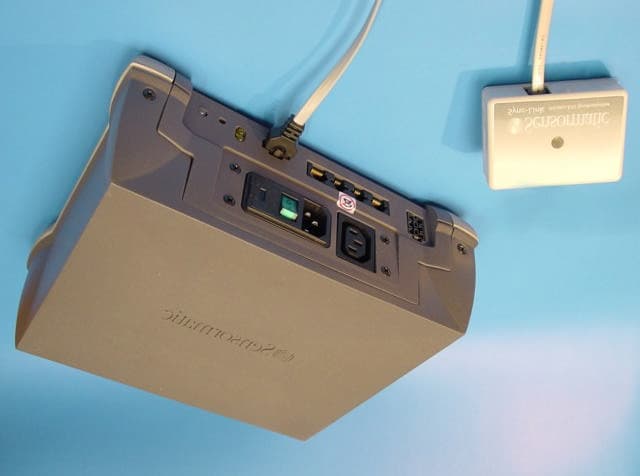
Click to zoom
Application Details
- Equipment Class
- DSS - Part 15 Spread Spectrum Transmitter
- Date of Grant
- Sep 23, 2002
- Application Purpose
- Original Equipment
- Date of Application
- Sep 23, 2002
- Equipment Note
- Anti-Theft Auxiliary Device
- Frequency Range
- 903.20000000 - 914.80000000
- Country
- United States
Documents & Files
Document Text
Text extracted from the exhibit documents filed with the FCC. Open a document above to read the original.
Users Manual
Preliminary AMC-4010 SYNCHRONIZATION MODULE INSTALLATION AND SERVICE GUIDE (8200-0183-01, REV. 03) 1 of 5 ZPSYNC4010 Wireless ZPSYNC4010 Wireless Sychronization Sychronization ModulesModules Setup GuideSetup Guide Wireless synchronization modules can significantly reduce electrical interference between Sensormatic EAS systems timed to the AC line. A module system includes a module designated as a transmitter and one or more modules designated as receivers. IMPORTANT! Ensure EAS devices can support wireless synchronization. IMPORTANT! The maximum distance between the transmit module and any receive module is approximately 60.1m (200 feet), but keep in mind that the range depends upon the environment in which the module is used. Many factors can limit the range, thus it would be impossible to list them. © Sensormatic 2002 For best performance, please follow these instructions carefully. Parts SuppliedParts Supplied Sync Link Module 1 0304-0029-01 Cable Ties 3 ? Cable 1 ? Mechanical SpecificationsMechanical Specifications Dimensions: 82mm (L) x 60mm (W) x 30mm (D) Weight: 2.5 oz Transmit FrequenciesTransmit Frequencies North America Frequency Hop: 903.2–914.8 MHz Europe Single Low frequency: 869.8 MHz Europe Single High frequency: 869.9 MHz Setting Up the TransmitterSetting Up the Transmitter 1. Find the EAS device that is central and within 60.1m (200 feet) of the others. Designate this device for use with the transmit module. IMPORTANT! DO NOT designate a mobile checkout stand or use with the transmit module. Only receive modules can be used with mobile checkout stands. 2. Configure one module as the transmitter by opening it and setting switch 7 to OFF (see Table on page 3). To access the switch, remove the holding screw and carefully separate the top and bottom covers (the side label serves as a hinge between the two covers. DO NOT remove this label). Preliminary AMC-4010 SYNCHRONIZATION MODULE INSTALLATION AND SERVICE GUIDE (8200-0183-01, REV. 03) 2 of 5 4. Close the module and reattach the holding screw. 5. Mount the transmit module: • As high as possible and in a location near the designated EAS device. The length of the cable supplied determines the distance the module can be from the device. IMPORTANT! Ensure the module will be within 60.1m (200 feet) of the transmit module. • In such a way that the two LEDs on the module can be readily see from below. Note: It is recommended to mount the module to an electrical access pole of a checkout counter by running a tie wrap through the two key slots on the back of the module and then running two additional tie warps through the tie wrap and around the pole (see box). Receivers (Rx) must be within 60.1m (200 feet) of the transmitter (Tx) 6. Using the cable supplied, connect the transmit module to the expansion port of the EAS device. Tx Rx Rx Rx Rx Rx Rx Switch 7 Preliminary AMC-4010 SYNCHRONIZATION MODULE INSTALLATION AND SERVICE GUIDE (8200-0183-01, REV. 03) 3 of 5 Setting Up a ReceiverSetting Up a Receiver 1. Mount each receive module: • As high as possible and in a location near the designated EAS device. The length of the cable supplied determines the distance the module can be from the device. IMPORTANT! Ensure the module will be within 60.1m (200 feet) of the transmit module. IMPORTANT! If mounting the module to a mobile checkout stand, mount it on the stand as high and as far away from obstructions and metal as possible. • In such a way that the two LEDs on the module can be readily see from below. Note: It is recommended to mount the module to an electrical access pole of a checkout counter by running a tie wrap through the two key slots on the back of the module and then running two additional tie warps through the tie wrap and around the pole (see box). 2. Using the cable supplied, connect the receive module to the expansion port of the EAS device. 3. Allow __ time for the modules to synchronize. Verifying OperationVerifying Operation Transmit ModuleTransmit Module Look at the transmit module. The green LED blinking with the red LED off is normal. Receiver Module(s)Receiver Module(s) Look at each receive module. The green LED glowing steadily with the red LED off is normal. Preliminary AMC-4010 SYNCHRONIZATION MODULE INSTALLATION AND SERVICE GUIDE (8200-0183-01, REV. 03) 4 of 5 TroubleshootingTroubleshooting Transmit ModuleTransmit Module If the red LED is blinking, this means that the power line connected to the EAS device it is connected to has noise on it. Use another EAS device to drive the transmit module. ReceivReceive Module(s)e Module(s) If the red LED is glowing steadily or flickering, this indicates that the module is either not receiving a signal from the transmit module or the signal is weak. Try moving the receiver 15.5 cm (6 inches) up or down the pole to allow it to receive a stronger signal. Mobile checkout stands: If the signal is weak, try moving the cart closer to the transmit module or away from obstacles that can block the signal. Switch settings for transmit or receive setup DIP Switch Settings Mode of Operation S1-1 S1-2 S1-3 S1-4 S1-5 S1-6 S1-7 S1-8 RX 60Hz North America Frequency hop OFF OFF ON ON ON ON ON X RX 50Hz Europe Single low frequency ON ON OFF OFF ON ON ON ON Europe Single high frequency ON ON OFF OFF ON ON ON OFF Europe Single frequency, auto-search OFF ON OFF OFF ON ON ON X TX 60Hz North America Frequency hop OFF OFF ON ON ON ON OFF X TX 50Hz Europe Single low frequency ON ON OFF OFF ON ON OFF ON Europe Single high frequency ON ON OFF OFF ON ON OFF OFF Preliminary AMC-4010 SYNCHRONIZATION MODULE INSTALLATION AND SERVICE GUIDE (8200-0183-01, REV. 03) 5 of 5 DeclarationsDeclarations Regulatory Regulatory ComplianceCompliance Emissions........................47 CFR, Part 15 RSS 210 EN 300 220 EN 301 489 Safety..............................UL1950 CSA C22.2 No 950 EN 60 950 FCC COMPLIANCE: This equipment complies with Part 15 of the FCC rules for intentional radiators and Class A digital devices w…
Text truncated - open the document above for the full version.
Cover Letter(s)
Sensormatic Electronics Corporation 951 Yamato Road, Boca Raton, FL 33431- 0700 Telephone (561) 989-7000 FAX (561) 989-7548 August 26, 2002 Timco Engineering, Inc. 849 N.W. State Road 45 P.O. Box 370 Newberry, Florida 32669 USA Re: Request for withholding from public disclosure proprietary information submitted pursuant to an application for certification for a low power transmitter. FCC ID: BVCDEACSLNK Dear Sir or Madam: Sensormatic requests certain materials submitted with this application for certification of device FCC ID: BVCDEACSLNK be withheld from public disclosure. This request is made under the provision of 47 CFR 0.457 (d) and 5 USC 552(b)(4) Freedom of Information Act, Trade Secrets. The items for which confidentiality is requested include the Operational Description, Block Diagram and Schematic Diagrams. This information contains proprietary information (trade secrets) regarding the circuit operation and capabilities (specific values of components, circuit design details and system architecture) which are the result of our extensive investment in research and development. Without the disclosed information, competitive organizations would take considerable more time to assess and develop a workable competitive product. As a result, we believe that disclosure of these company-guarded materials would compromise our leading position in this market. We therefore formally request that the materials identified “Confidential” be kept strictly confidential and not made available for inspections by any other party, except on a need to know basis for the sole purpose of the certification process. Sincerely, Donald J. Umbdenstock Sr. Principal Engineer, Compliance Engineering Tyco Safety Products -- Sensormatic
Cover Letter(s)
RESPONSES, CORRESPONDENCE 5528 Comment 1 and 2 address frequencies at 86x MHz. Response: The product is not offered in the United States at frequencies of 86x MHz. The Setup Guide is written for the factory-trained installer, not the user. Therefore there is no information available to the user regarding the setting of the frequencies to European frequencies of 86x MHz. The factory-trained installer is trained to set up the equipment for the 903 – 914 MHz band in the United States; the installer has been trained not to apply European frequency bands in the US. As we are not requesting approval for frequencies in the 86x MHz range; a form 731 and related data will not be submitted for this range. Comment 3 requests new band edge data at 100 kHz RBW. Response: The new plots are included in Appendix 1. Comment 4 is looking for an update to the installation manual addressing the 20 cm spacing for exposure. Response: A statement regarding exposure was crafted with the assistance of the FCC for FCC ID: BVCDMS915. As the DMS product transmitted 20 times the power that the Sync Link transmits and is used in a similar environment, we believe the same statement will be more than adequate. The modified page of the Setup Guide is included in Appendix 2. The added statement is located on the lower left side of the page. The box outline makes the statement conspicuous. Appendix 1: Band Edge Measurements at 100 kHz RBW Frequency Hopping High Side Non-Hopping High Side Frequency Hopping Low Side Appendix 2: Installation Manual Update ZPSYNC4010 Wireless Sychronization Modules Setup Guide Wireless synchronization modules can significantly reduce electrical interference between Sensormatic EAS systems timed to the AC line. A module system includes a module designated as a transmitter and one or more modules designated as receivers. IMPORTANT! Ensure EAS devices can support wireless synchronization. © Sensormatic 2002 IMPORTANT! The maximum distance between the transmit module and any receive module is approximately 60.1m (200 feet), but keep in mind that the range depends upon the environment in which the module is used. Many factors can limit the range, thus it would be impossible to list them. For best performance, please follow these instructions carefully. Parts Supplied Sync Link Module 1 0304-0029-01 Cable Ties 3 ? Cable 1 ? Mechanical Specifications Dimensions: 82mm (L) x 60mm (W) x 30mm (D) Weight: 2.5 oz Transmit Frequencies North America Frequency Hop: 903.2–914.8 MHz Europe Single Low frequency: 869.8 MHz Europe Single High frequency: 869.9 MHz Setting Up the Transmitter 1. Find the EAS device that is central and within 60.1m (200 feet) of the others. Designate this device for use with the transmit module. IMPORTANT! DO NOT designate a mobile checkout stand or use with the transmit module. Only receive modules can be used with mobile checkout stands. 2. Configure one module as the transmitter by opening it and setting switch 7 to OFF (see Table on page 3). To access the switch, remove the holding screw and carefully separate the top and bottom covers (the side label serves as a hinge between the two covers. DO NOT remove this label). Note to installers: For FCC compliance, the module must be located where persons are not likely to linger within 20 cm (8”) of the RF antennas. A 20 cm (8”) setback is not required provided the antenna location does not promote lingering within 20 cm (8”) of the antennas. For example, do not locate antennas adjacent to a chair or bench.
Cover Letter(s)
RESPONSES, CORRESPONDENCE 5528 AND 6126 Comment 1 and 2 address frequencies at 86x MHz: 1) Updated Form 731 tech spec line to include 86x MHZ frequency emission. Device appears to be tuneable to these frequencies by the user. Alternatively, detail how user will be prevented from tuning device to European modes. User manual controls suggest user can make this adjustment. 2) Full test results associated with 86x MHZ transmission as appropriate. Response to questions 1 and 2: The product is not offered in the United States at frequencies of 86x MHz. The Setup Guide is written for the factory-trained installer, not the user. Therefore there is no information available to the user regarding the setting of the frequencies to European frequencies of 86x MHz. The factory-trained installer is trained to set up the equipment for the 903 – 914 MHz band in the United States; the installer has been trained not to apply European frequency bands in the US. As we are not requesting approval for frequencies in the 86x MHz range; a form 731 and related data will not be submitted for this range. Comment 3 requests new band edge data at 100 kHz RBW: 3) New band edge data. Please use 100 KHz RBW as required. Response: The new plots are included in Appendix 1. Comment 4 is looking for an update to the installation manual addressing the 20 cm spacing for exposure: 4) Updated grant comment and user manual to included antenna instructions to maintain a 20 cm spacing to all persons. Response: A statement regarding exposure was crafted with the assistance of the FCC for FCC ID: BVCDMS915. As the DMS product transmitted 20 times the power that the Sync Link transmits and is used in a similar environment, we believe the same statement will be more than adequate. The modified page of the Setup Guide is included in Appendix 2. The added statement is located on the lower left side of the page. The box outline makes the statement conspicuous. Appendix 1: Band Edge Measurements at 100 kHz RBW Frequency Hopping High Side Non-Hopping High Side Frequency Hopping Low Side Appendix 2: Installation Manual Update ZPSYNC4010 Wireless Sychronization Modules Setup Guide Wireless synchronization modules can significantly reduce electrical interference between Sensormatic EAS systems timed to the AC line. A module system includes a module designated as a transmitter and one or more modules designated as receivers. IMPORTANT! Ensure EAS devices can support wireless synchronization. © Sensormatic 2002 IMPORTANT! The maximum distance between the transmit module and any receive module is approximately 60.1m (200 feet), but keep in mind that the range depends upon the environment in which the module is used. Many factors can limit the range, thus it would be impossible to list them. For best performance, please follow these instructions carefully. Parts Supplied Sync Link Module 1 0304-0029-01 Cable Ties 3 ? Cable 1 ? Mechanical Specifications Dimensions: 82mm (L) x 60mm (W) x 30mm (D) Weight: 2.5 oz Transmit Frequencies North America Frequency Hop: 903.2–914.8 MHz Europe Single Low frequency: 869.8 MHz Europe Single High frequency: 869.9 MHz Setting Up the Transmitter 1. Find the EAS device that is central and within 60.1m (200 feet) of the others. Designate this device for use with the transmit module. IMPORTANT! DO NOT designate a mobile checkout stand or use with the transmit module. Only receive modules can be used with mobile checkout stands. 2. Configure one module as the transmitter by opening it and setting switch 7 to OFF (see Table on page 3). To access the switch, remove the holding screw and carefully separate the top and bottom covers (the side label serves as a hinge between the two covers. DO NOT remove this label). Note to installers: For FCC compliance, the module must be located where persons are not likely to linger within 20 cm (8”) of the RF antennas. A 20 cm (8”) setback is not required provided the antenna location does not promote lingering within 20 cm (8”) of the antennas. For example, do not locate antennas adjacent to a chair or bench.
Cover Letter(s)
Please refer to the attached email thread. It originated from Mr. Kwok Chan of the FCC, regarding an anti-theft device that operated at 125 mW. As the device mentioned below is an anti-theft device operating at 5 mW, the guidelines from the above email are applicable. Item 4 of the above email from Mr. Chan states: > 4. It would be appropriate to include installation instructions to alert > installers that the antennas should be installed in manners to minimize > the likelihood of persons remaining in front of the antenna at closer than > 20 cm for prolong periods, for meeting FCC RF exposure requirements. > Based on the operating nature of this system and the maximum output > measured, the likelihood of people remaining at closer than 20 cm in front > of the antenna for prolong periods that could result in undesired > exposures is rather remote, provided the antennas are not installed at > locations that could promote such undesirable conditions. A specific 20 > cm setback is not necessary as long as the above is observed by the > installers. The applicable changes should be incorporated in the manual > or provided to the installers. The revised instructions should be > uploaded for this filing. > Therefore, I believe no change in the language below is necessary. Let me know if any further discussion is required. From: [email protected] Sent: Monday, January 22, 2001 4:00 PM To: [email protected] Cc: [email protected] Subject: RE: FCC ID: BVCDMS915, Sensormatic Mr. Chan, Thank you for your speedy and thorough reply. Our team leaders met and developed the response which was provided to Mr. Chang via "submit correspondence" on the FCC filing site. The manual containing the notice to the installers was also uploaded. The notice is as follows: "Note to Installers: For FCC compliance, system components must be located where persons are not likely to linger within 20 cm (8") of the RF antennas. A 20cm (8") setback is not required provided the antenna location does not promote lingering within 20cm (8") of the antennas. For example, do not locate antennas adjacent to a chair or bench." Thank you for your assistance. Kind regards, Don Umbdenstock > ---------- > From: Kwok Chan[SMTP:[email protected]] > Sent: Friday, January 19, 2001 5:53 PM > To: [email protected] > Cc: Errol Chang; Kwok Chan > Subject: Re: FCC ID: BVCDMS915, Sensormatic > > > Mr. Umbdenstock: > > After checking with Mr. Errol Chang, reviewing the info submitted for this > filing and your e-mail, the follow is a summary of what I have gathered - > > 1. This is a spread spectrum transmitter system that operates under 15.247 > of the rules. The RF exposure requirements of 15.247(b)(4) require these > types of transmitters to operate in a manner that will ensure the public > is not exposed to RF energy levels in excess of the Commission's > guidelines. For exposure purposes, a transmitter may be classified as a > fixed, mobile or portable transmitter. Fixed transmitters are those > defined in Table 1 of 1.1307, operating with specific antenna height > requirements, such as basestation and broadcast transmitters where the > exposure conditions are generally in the far-field of the antenna(s) > mounted on a tower, roof-top or similar structures. Mobile transmitters > are those that are not fixed but operate at 20 cm or more from persons and > the exposure conditions are typically in the near-to-far field transition > regions of an antenna/transmitter. Field strength and power density > limits for free-space conditions are applicable for fixed and mobile > transmitters. Portable transmitters are those that are designed to be > used within 20 cm of a user's body and compliance is with respect to SAR > limits (based on energy absorption in tissues). The antenna > configurations described in this filing are intended for used in > situations that would typically be 20 cm or more from persons, as > indicated in the reply received on 01/12/01 for the filing. The > transmitter system and its antennas are not designed to be used at close > proximity to persons. The people exposed would not know of their exposure > conditions as compare to users of typical hand-held wireless phones. They > are generally treated as bystanders instead of users of a transmitter. It > would be appropriate to treat this system as a mobile transmitter. > Treating it as a fixed transmitter would not change the exposure > requirements for purpose of satisfying 15.247(b)(4) since far-field > conditions should extend beyond the near-to-far field transition region > and the same power density limit applies to both types of transmitters. > > 2. A peak conducted output of 125 mW was measured at the output terminal. > Although the system uses two antennas (125 mW each), when one antenna > becomes closer to a person the other antenna is further away by nature of > the system installation and operating requirements. Therefore, it would > not be necessary to consider the exposure conditions due to two antennas. > > 3. Part 15.247 requires peak conducted output, which was measured as 125 > mW. The filing has requested for 250 mW, which appears to be based on the > maximum EIRP with respect to the highest antenna gain. The output will be > listed as 125 mW as specified by the rules. Additional grant comments > will be used to clarify that the output is for each antenna and the > antennas must be installed to provide a minimum separation distances > described in the installation instructions submitted to this filing. > > 4. It would be appropriate to include installation instructions to alert > installers that the antennas should be installed in manners to minimize > the likelihood of persons remaining in front of the antenna at closer than > 20 cm for prolong periods, for meeting FCC RF exposure requirements. > Based on the operating nature of this system and the maximum output > measured, the likelihood of people remaining at closer than 20 cm in front > of the antenna …
Text truncated - open the document above for the full version.
External Photos
Scan Max Pro Deactivator (Host Unit) Sync-Link Module Interface Cable
ID Label/Location Info
FCC ID: BVCDEACSLNK THIS DEVICE COMPLIES WITH PART 15 OF THE FCC RULES. OPERATION IS SUBJECT TO THE FOLLOWING TWO CONDITIONS: (1) THIS DEVICE MAY NOT CAUSE HARMFUL INTERFERENCE, AND (2) THIS DEVICE MUST ACCEPT ANY INTERFERENCE RECEIVED, INCLUDING INTERFERENCE THAT MAY CAUSE UNDESIRED OPERATION. IC: 3506A-DEACSLNK N205 MADE IN PUERTO RICO
ID Label/Location Info
Label Location
Test Report
FCC ID: BVCDEACSLNK IC: 3506A-DEACSLNK 1 Appendix II Test Report Cover Sheet COMPANY NUMBER: 3506A MODEL NUMBER: DEAC SLNK MANUFACTURER: Tyco Safety Products -- Sensormatic TESTED TO RADIO STANDARD SPECIFICATION NO. : RSS 210 OPEN AREA TEST SITE INDUSTRY CANADA NUMBER: 3506 FREQUENCY RANGE (or fixed frequency): 903.2 – 914.8 R.F. POWER IN WATTS: .004 FIELD STRENGTH (at what distance): OCCUPIED BANDWIDTH (99% BW): 135 kHz TYPE OF MODULATION: FSK EMISSION DESIGNATOR (TRC-43): 135KF1D TRANSMITTER SPURIOUS (worst case): -61dBm RECEIVER SPURIOUS (worst case): na; transmitter on continuously ATTESTATION: I attest that the testing was performed or supervised by me; that the test measurements were made in accordance with the above mentioned departmental standard(s), and that the radio equipment identified in this application has been subject to all the applicable test conditions specified in the departmental standards and all of the requirements of the standard have been met. Signature: Date: 26 August 27, 2002 NAME AND TITLE (Please print or Type): Donald J. Umbdenstock Sr. Principal Engineer, Compliance Engineering . FCC ID: BVCDEACSLNK IC: 3506A-DEACSLNK 2 Note: This form must be completed and provided with the submission. COMPANY Sensormatic Electronics Corp. 6600 Congress Ave Boca Raton, Florida 33487 PRODUCT TESTED Modular Device – Sync Link FCC ID: BVCDEACSLNK IC: 3506A-DEACSLNK FCC RULES 15.207, 15.209, 15.247 TEST DATE June 15-August 23, 2002 SUBMITTED BY Donald J. Umbdenstock FCC ID: BVCDEACSLNK IC: 3506A-DEACSLNK 3 INDEX I. SUMMARY OF RESULTS 3 II. GENERAL INFORMATION 3 Test Methodology 3 Test Facility 3 System Description 4 15.203 Compliance 4 15.204 Compliance 4 III. CONDUCTED EMISSIONS TESTING, 15.207 5 IV. FREQUENCY HOPPING REQUIREMENTS, 15.247 5 Pseudorandom Frequency Hopping Sequence 5 Equal Hopping Frequency Use 5 System Receiver Hopping Capability 6 System Receiver Input Bandwidth 6 RF Exposure Compliance Information 7 V LIST OF MEASUREMENT EQUIPMENT 8 VI. DATA 9 Part A – Conducted Emissions 9 Part B – Frequency Hopping Data 11 Carrier Frequency Separation 11 Number of Hopping Channels 12 Dwell Time 13 20 dB Bandwidth 14 Peak Power 15 Band Edge Compliance of RF Conducted Emissions 16 Part C – 15.205, 15.209 Data, Spurious Radiated Emissions 18 FCC ID: BVCDEACSLNK IC: 3506A-DEACSLNK 4 I. Summary of Results 47 CFR 15.207 CONDUCTED EMISSIONS COMPLIES 47 CFR 15.209 RADIATED EMISSIONS COMPLIES 47 CFR 15.247 FREQUENCY HOPPING COMPLIES II. General Information 1.1 Test Methodology Both conducted and radiated emissions testing were performed according to the procedures in ANSI C63.4-1992, and the requirements of 15.31, 15.33, 15.35, 15.207, 15.209 and 15.247. In addition, radiated emissions were measured per FCC document DA 00-705, “Filing and Measurement Guidelines for Frequency Hopping Spread Spectrum Systems”, and conducted emissions were measured per FCC document DA 00-1407, “Part 15 Unlicensed Modular Transmitter Approval”. DA 00-705 calls for conducted RF measurements. The device is manufactured with an integral antenna. To accommodate the conducted RF measurements, a unit was modified to replace the antenna with an external SMA connector. Another unmodified unit was used for radiated spurious emissions. The modified unit is a test item only and is not available for sale. 15.31 (m) calls for measurements to be made at the highest and lowest frequencies. Measurements were made at 903.2 MHz and 914.8 MHz except where frequency hopping was called for. 1.2 Test Facility Measurements were performed at Sensormatic Electronics. The shielded room conducted emissions measurement facility is located at Sensormatic Electronics Corporation Headquarters at 6600 Congress Avenue, Boca Raton, Florida, 33487. The radiated emissions Open Area Test Site is also located at 6600 Congress Avenue, Boca Raton, Florida 33487. These sites FCC ID: BVCDEACSLNK IC: 3506A-DEACSLNK 5 have been found acceptable by and are on file with the FCC per FCC Registration Number 90925, and Industry Canada per file number IC 3506. FCC ID: BVCDEACSLNK IC: 3506A-DEACSLNK 6 1.3 Test System Description. The sync-link module is a UHF transmitter and receiver device that operates in the 860 to 930MHz region. It can be set up as either a receiver or transmitter via a dipswitch setting. It is designed to provide wireless synchronization of Sensormatic’s Electronic Article Surveillance (EAS) equipment. This is accomplished by setting one sync-link module up as a transmitter; this connects to a host EAS device that supplies the sync-link with a timing reference. The sync-link takes the timing reference and modulates it onto the UHF carrier. Other EAS devices that are equipped with sync-link receivers are supplied with the timing reference from the sync-link demodulated output. The sync-link module can be set up via dipswitch settings to work either in North America where it uses a carrier frequency of 902 – 928 MHz or in Europe where is uses 868-869 MHz carrier frequency. In North America it operates in frequency hopping mode, where it hops though a random sequence of 60 frequencies. The product is a self-contained module including all the circuitry to generate and transmit the carrier. Contained within the device are its regulated power supply, frequency reference, and integral antenna. The only signals coming in to the transmitter are power and modulation data. The receiver provides a demodulated output routed to EAS equipment. The product tested was a pre-production unit built to production drawings. 15.203,15.204,. The antenna which is a quarter wave mono-pole 24 gauge wire is soldered directly to the PCB. The PCB along with the antenna is enclosed in a plastic housing. The antenna is manufactured by Sensormatic. The gain of the antenna with reference to an isotropic radiator is -1.4 dBi. FCC ID: BVCDEACSLNK IC: 3506A-DEACSLNK 7 III. Conducted Emissions An external power supply provided the 5 Vdc input to the LISN that powered…
Text truncated - open the document above for the full version.
Test Setup Photos
Conducted Emissions Setup Radiated Emissions Setup
Contact Information
Applicant
Mark D. Alexis(Manager Regulatory Compliance)
Test Firm
Sensormatic Electronics CorporationWilliam Elliott
Technical Specifications
| # | Rule Parts | Frequency Range | Power Output |
|---|---|---|---|
| 1 | 15C | 903.2 MHz - 914.8 MHz | 5.00 mW |
Other Applications from Tyco Safety Products/Sensormatic

BVCIDX5000
Jun 23, 2026UHF RFID Reader
Equipment Class
DSS - Part 15 Spread Spectrum TransmitterBVCAMS1137H
Dec 22, 2025Anti Theft System - Electronic Asset Security
Equipment Class
FAP - Part 15 Anti-Pilferage DeviceBVCAMB9012
Sep 10, 2024Label Deactivator Controller
Equipment Class
DCD - Part 15 Low Power Transmitter Below 1705 kHz
BVC-4000-PI26
Sep 24, 2015RM2L-4000-P126, RM2-4000-P126
Equipment Class
DXX - Part 15 Low Power Communication Device Transmitter
BVCAMS90604
May 20, 2014Anti-pilferage Device
Equipment Class
FAP - Part 15 Anti-Pilferage Device