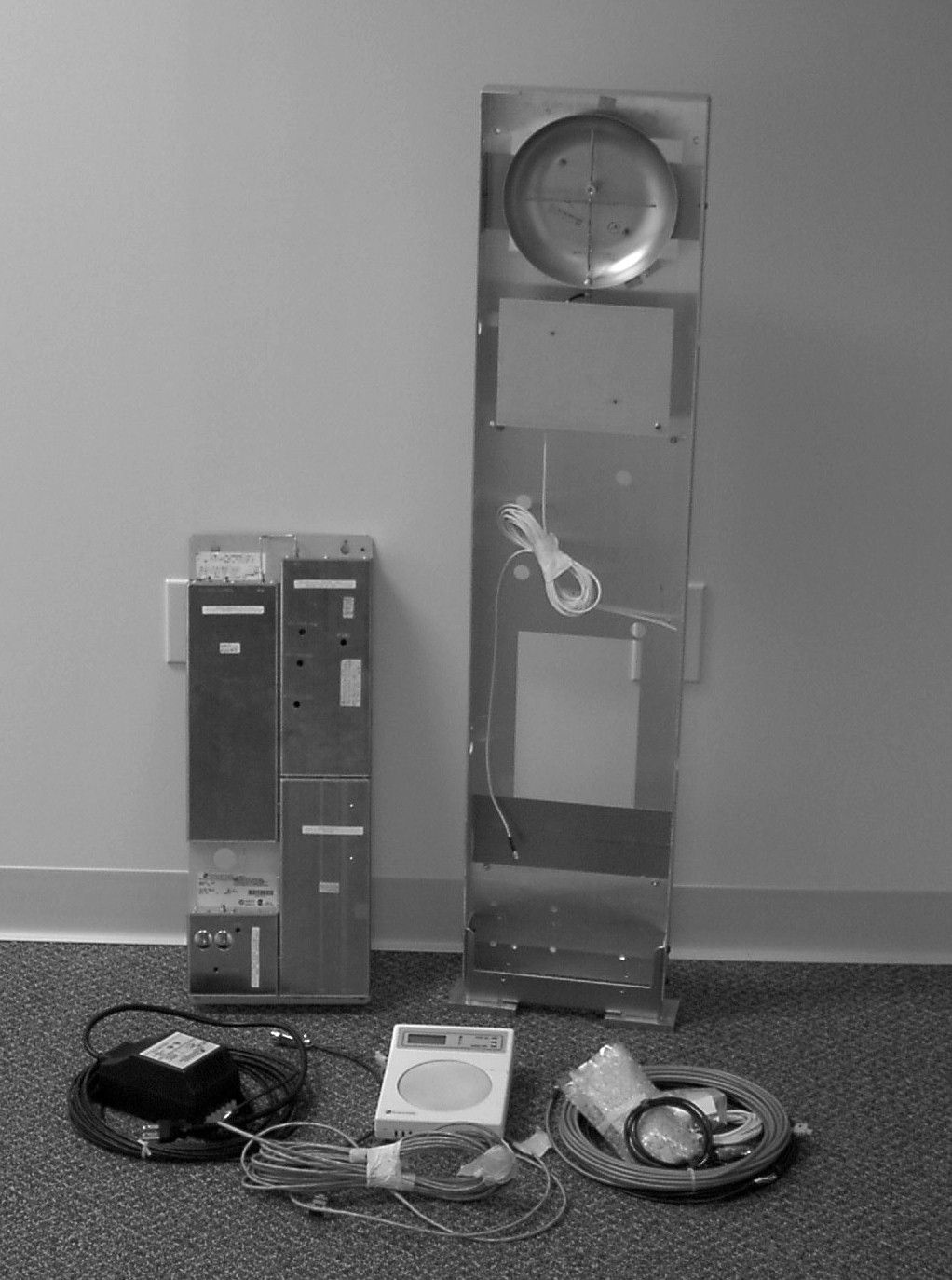
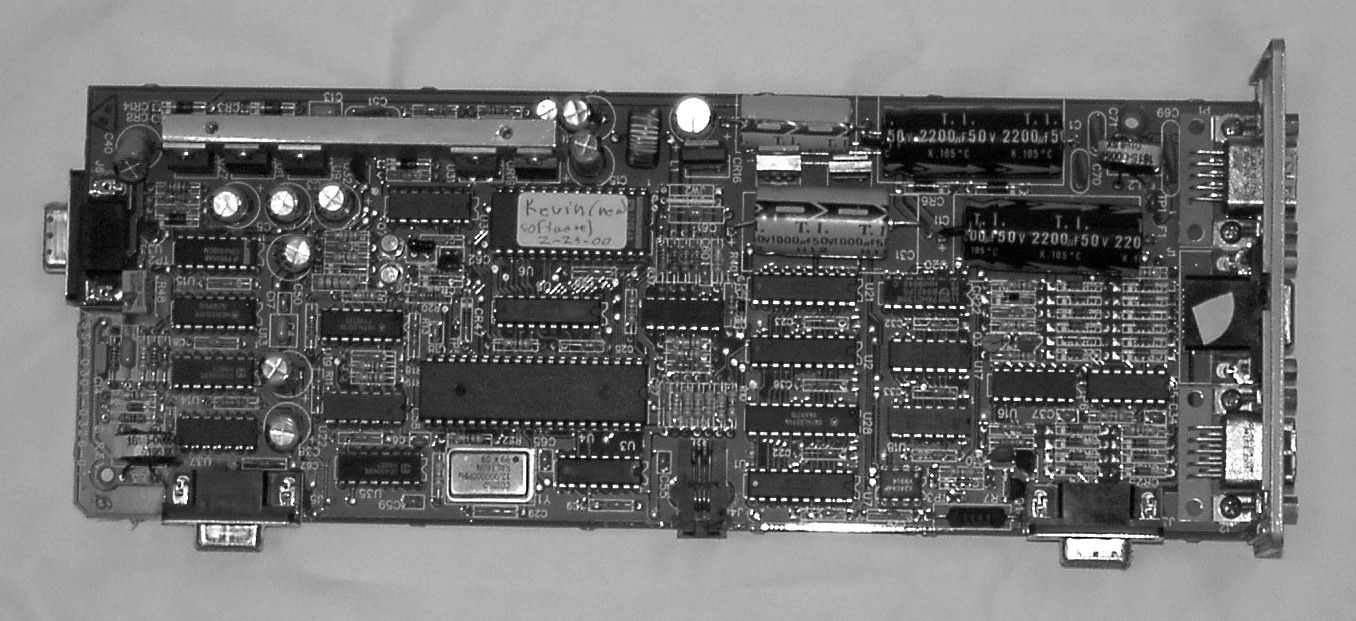
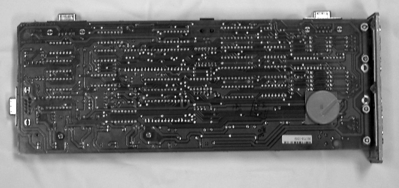
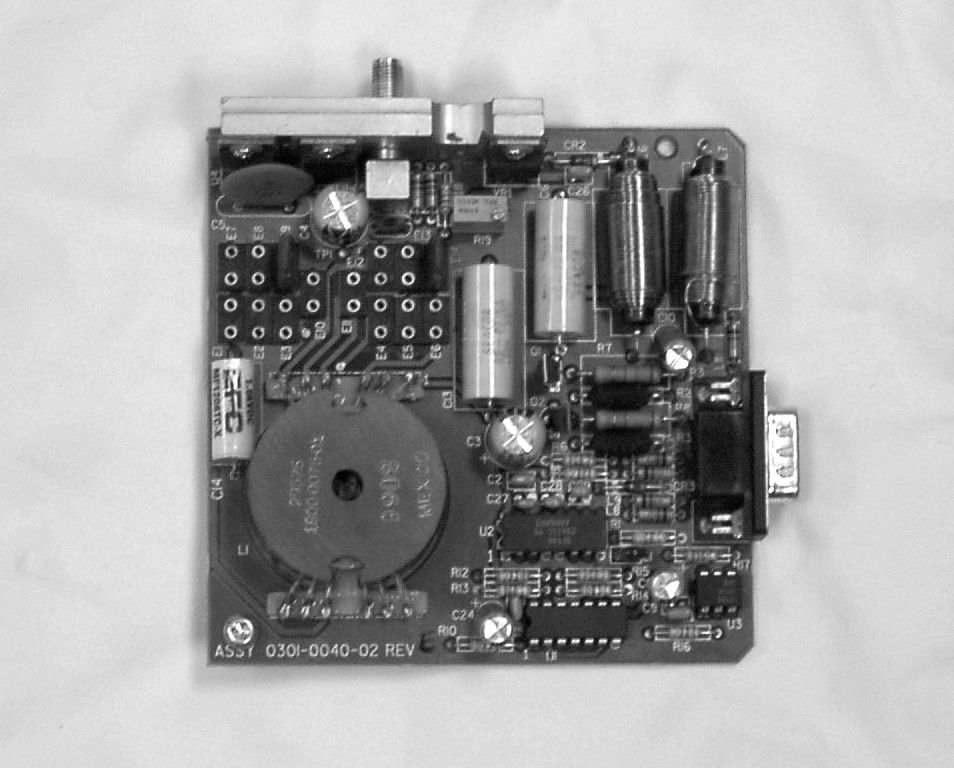
BVCDMS915Digital Microwave System anti-theft equipment
Tyco Safety Products/Sensormatic
Click to zoom
Application Details
- Equipment Class
- DSS - Part 15 Spread Spectrum Transmitter
- Date of Grant
- Jan 23, 2001
- Application Purpose
- Original Equipment
- Date of Application
- Oct 29, 2000
- Equipment Note
- Digital Microwave System anti-theft equipment
- Frequency Range
- 902.00000000 - 905.00000000
- Country
- United States
Documents & Files
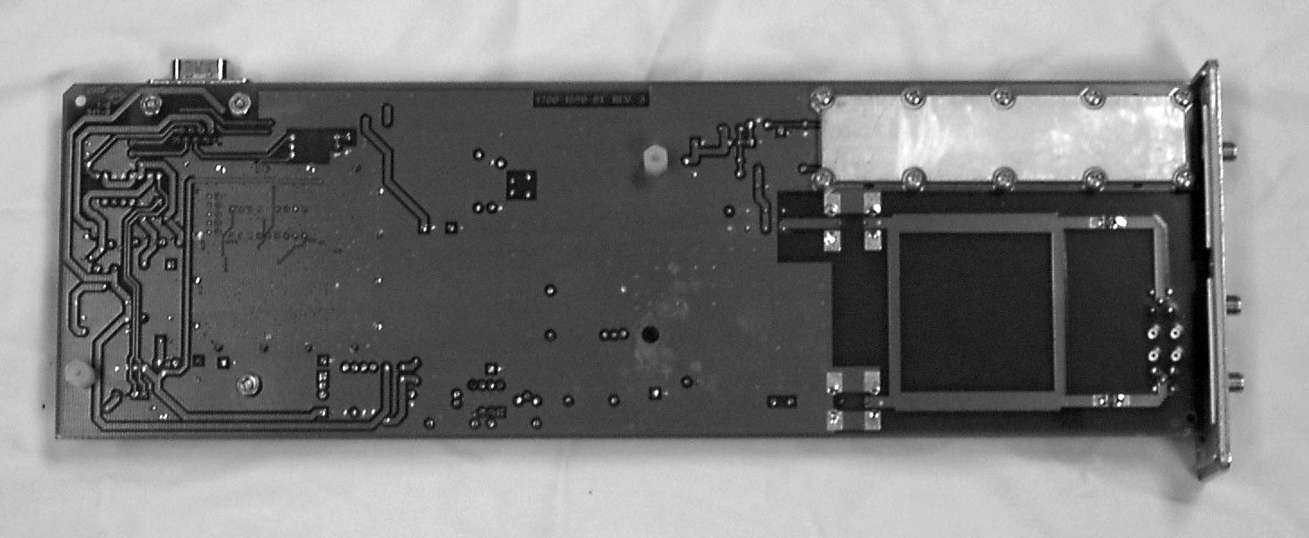
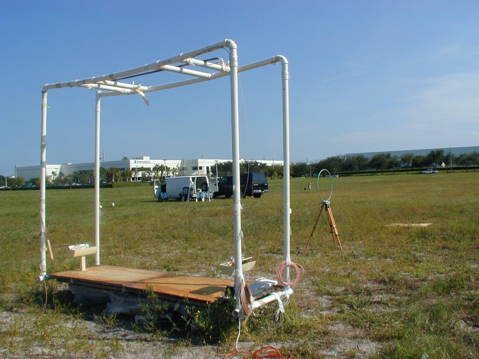

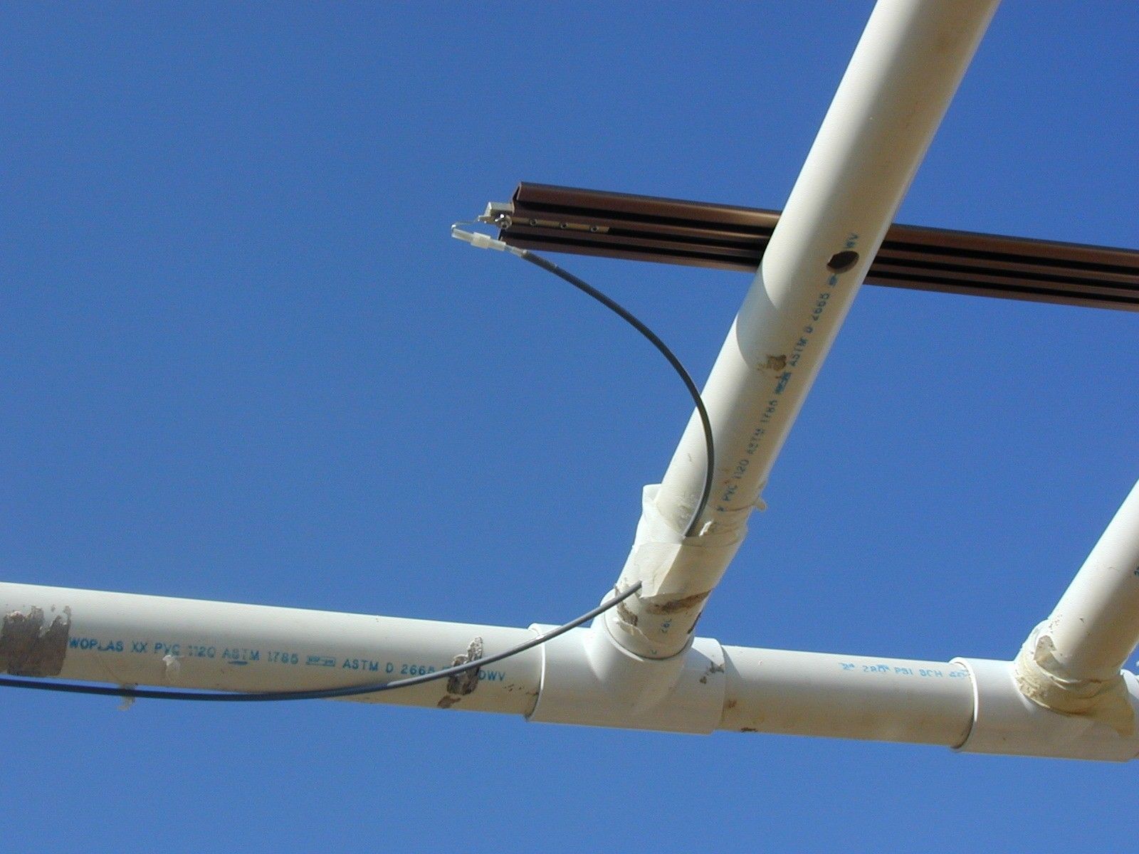
Document Text
Text extracted from the exhibit documents filed with the FCC. Open a document above to read the original.
Users Manual
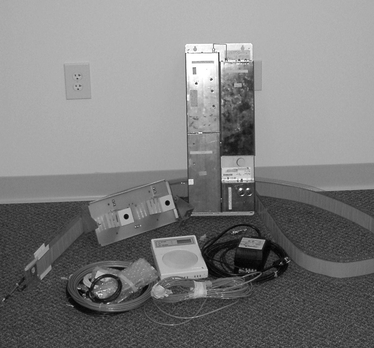
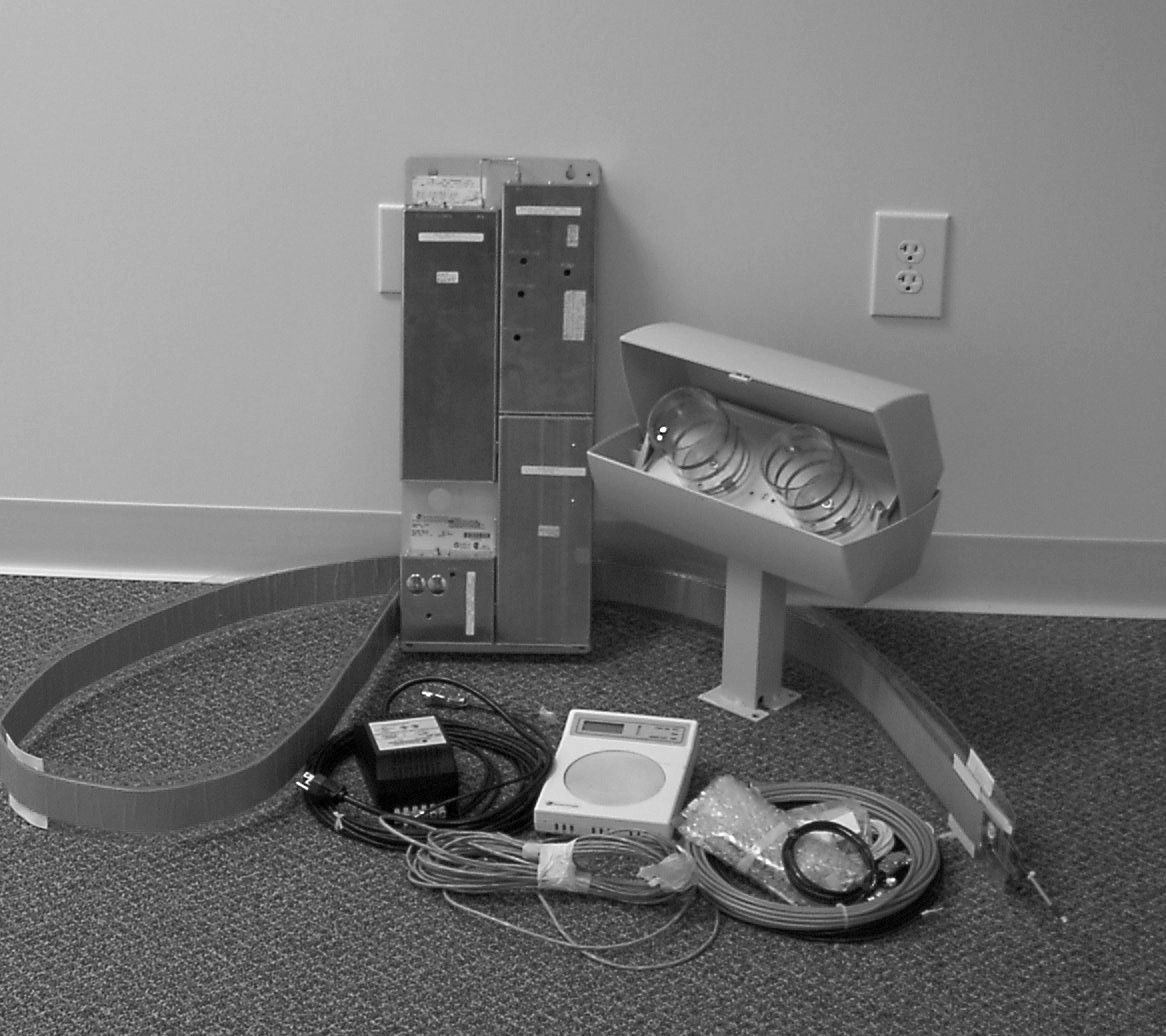
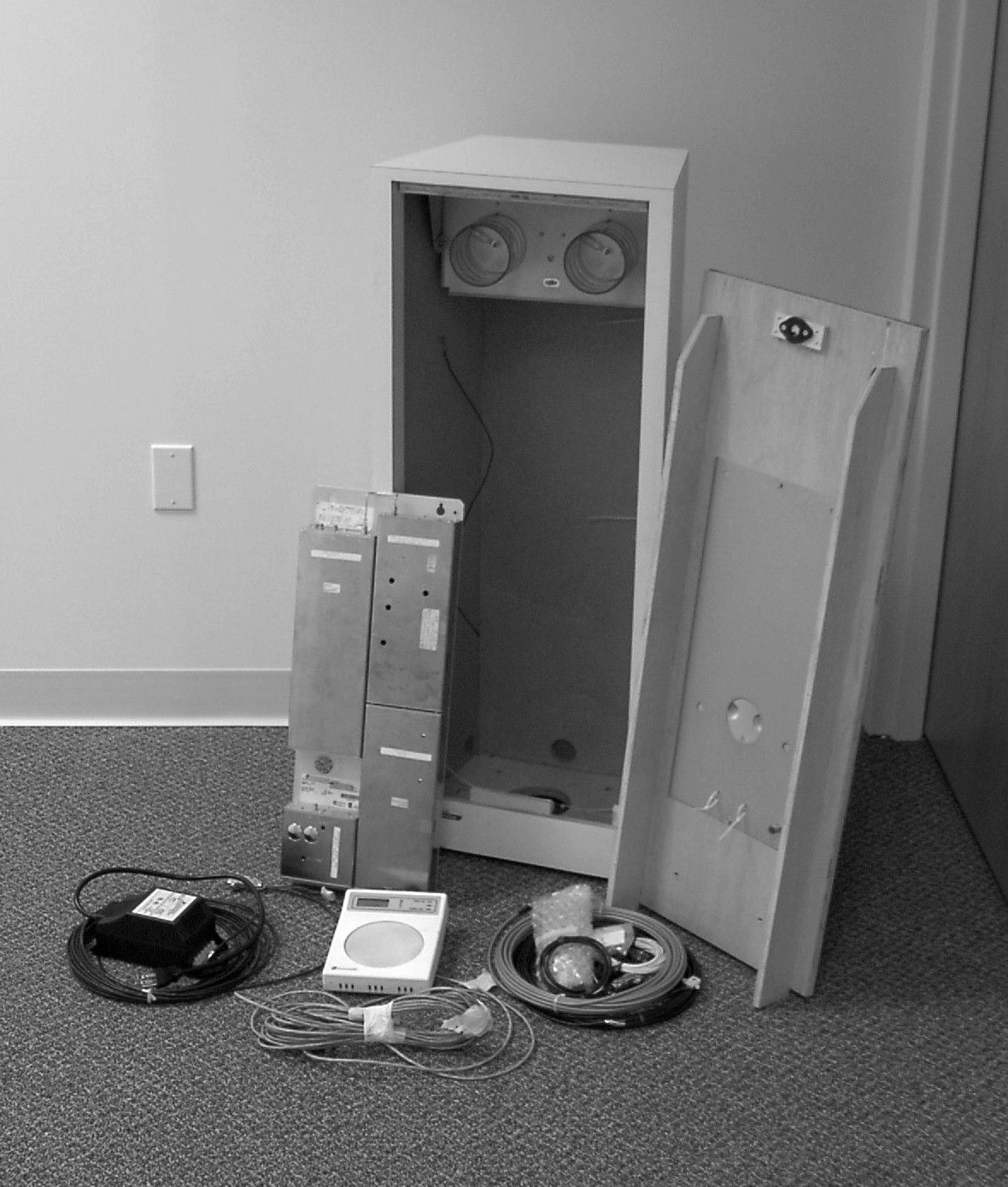
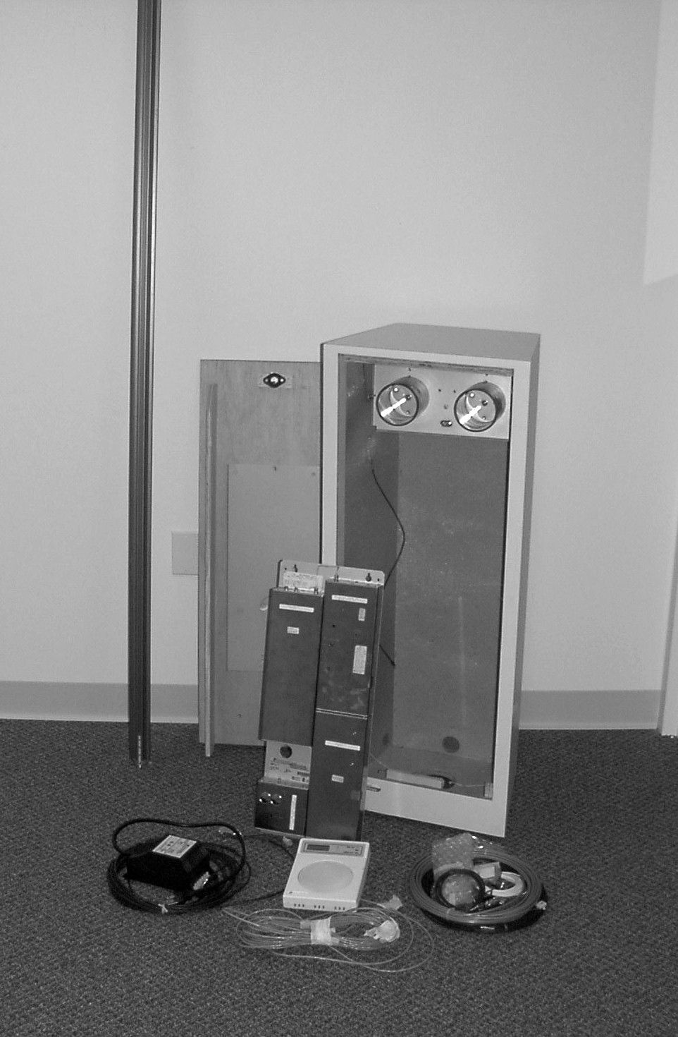
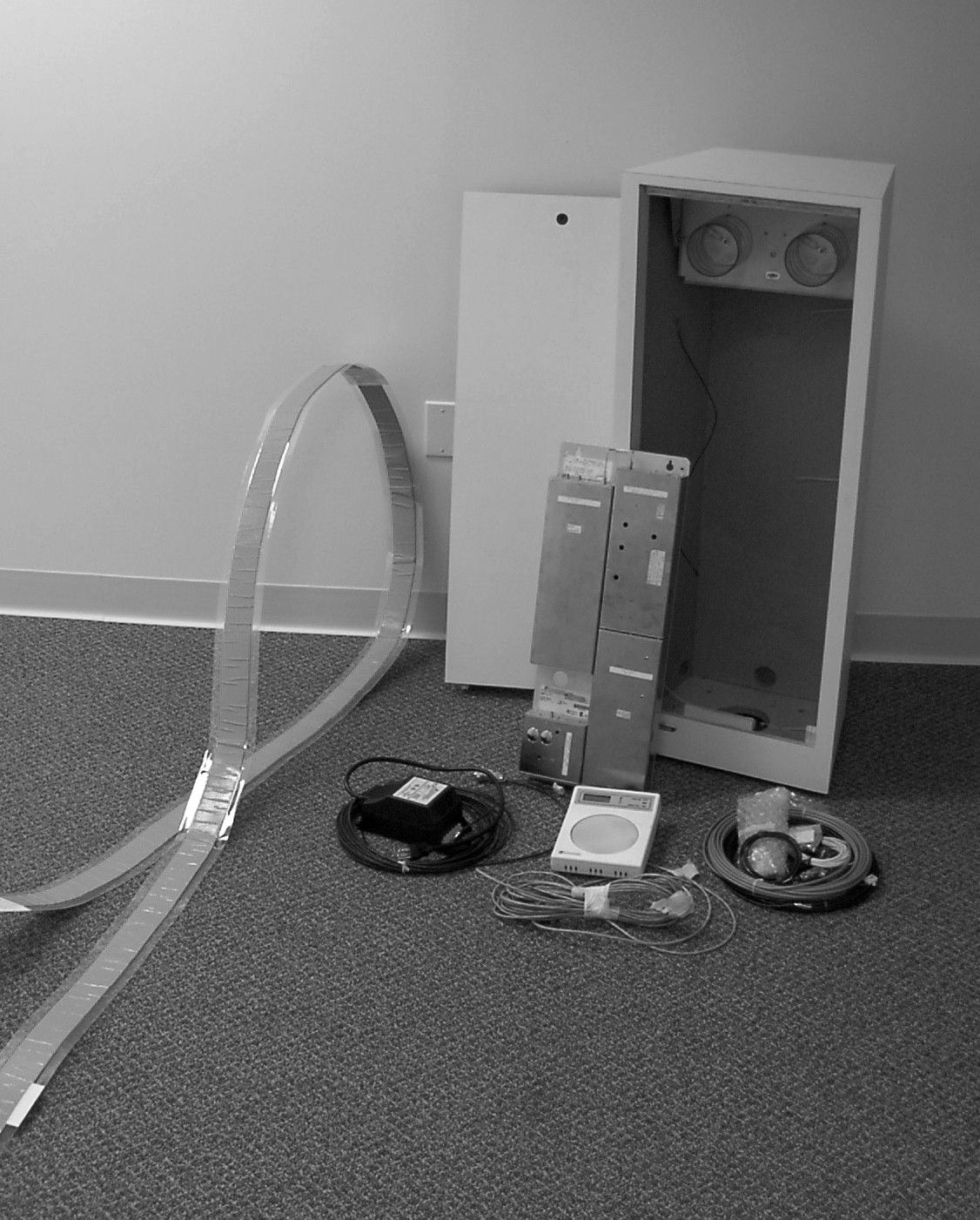
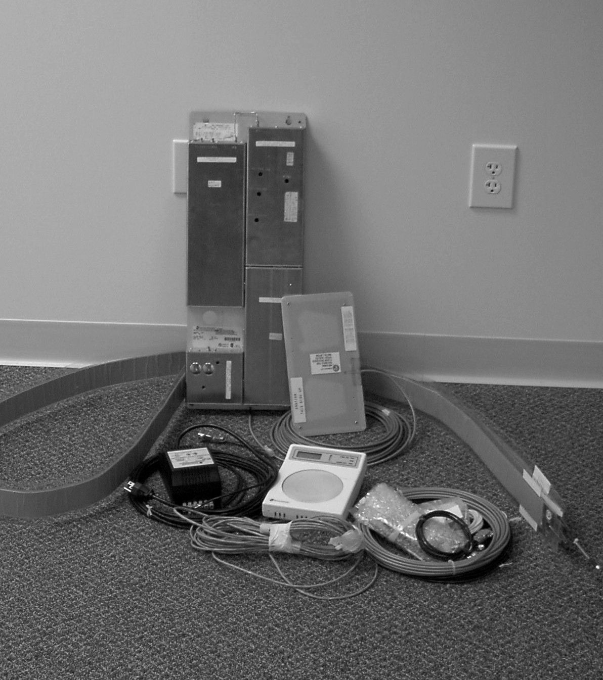
WORLD LEADER IN ELECTRONIC SECURI TY Setup and Service Guide 8000-0395-02, Rev. A (9 pages) MICROWAVE PRODUCTS1 1 Digital Microwave System 915 Addendum EADC12WC DMS Concealed 12' EADC18WC DMS Concealed 18' EADC24WC DMS Concealed 24' EADM06DMS Micromax 6' EADM06WC DMS Micromax WC 6' EADM12DMS Micromax 12' EADM12WC DMS Micromax WC 12' EADM18DMS Micromax 18' EADM18WC DMS Micromax WC 18' EADM24DMS Micromax 24' EADP06DMS Pedestal 6' EADP18WC DMS Pedestal WC 18' EADR03WC DMS Sensormat II 3' EADR06WC DMS Sensormat II 6' EADR10WC DMS Sensormat II 10' EADS03DMS Slimline 3' EADS06DMS Slimline 6' Contents About this Guide................................................ 1 About the DMS 915 ........................................... 2 Specifications.................................................... 9 Declarations...................................................... 9 About this Guide This Setup and Service guide explains typical installations and tuning for the DMS 915 detector. It is intended to be used as a supplement to the DMS 915 Installation and Field Service Manual. Refer to the DMS 915 manual for a complete description of theory, installation, and troubleshooting. Other related documents are: • DMS 915 Installation and Field Service Manual, 8000-0395-01 Note: Because customer requirements dictate the placement of detector components, your Sensormatic representative will supply this information separately. If you need assistance... Call Sensormatic Customer Support at: 1-800-543-9740 Micromax, Sensormatic , and the Sensormatic logo are registered trademarks of Sensormatic Electronics Corporation. Other product names (if any) mentioned herein may be trademarks or registered trademarks of other companies. No part of this guide may be reproduced in any form without written permission from Sensormatic Electronics Corporation. © Copyright 2000. All rights reserved. (DOJ) 11/00 Preliminary – 11/03/00 2SETUP AND SERVICE GUIDE DIGIT AL MICROW AVE S YSTE M 915 8000-0395-02, REV. A About the DMS 915 The Digital MicroWave System (DMS) 915 is a microcontroller-based anti-theft system. The DMS 915 produces an alarm when it detects a Sensormatic tag, a packaged semiconductor diode. To detect the tag, the system performs the following operations: • The system generates a “zone of protection,” typically at a store exit. This zone consists of two overlapping fields. The first field is a static or frequency-hopping, frequency modulated RF signal. The second field is a frequency shift key (FSK) modulated and predominately electrostatic field called an E-field. • When a tag enters the zone, it combines the RF signal and the E-field into a composite signal that radiates to the system RF antennas. The system detects the composite signal, separates the modulation, and compares the recovered modulation to the modulation transmitted. If the two signals match, the system issues an alarm. The DMS 915 is programmed using an external hand-held computer. Programmable features include RF hopping bank or frequency selection, RF power level selection, electrostatic field frequency selection, “tag-too-close” function enable/disable, alarm tone selection, alarm duration selection, selectable hits required for alarm, and alarm count set/reset control. System Components DMS 915 components include E-field radiators, RF antennas, remote alarms, and a programmable power pack Three types of E-field radiators are: • Wire cloth – usually recessed in the floor or sometimes laid on the floor under a rubber pad. • Plate – a metal plate concealed inside a pedestal at the side of the exit. • Vortex – a long aluminum bar hung across the exit. The RF antennas are used to radiate the frequency-hopping, frequency-modulated RF signal. These antennas mount in a variety of ways. They can be concealed above the ceiling, mounted in pods, concealed in the floor, or mounted in pedestal enclosures located at the store exit. The remote alarm provides a audio/visual signal that a tag has entered the “zone of protection.” The power pack powers and controls the system. The pack is typically concealed inside an enclosure. DIGIT AL MICROW AVE S YSTE M 915 8000-0395-02, Rev. A SETUP AND SERVICE GUIDE3 Typical Installations DMS 915 components are arranged in various configurations depending on the application. Typical installations are: • Slimline with plates • Concealed ceramic RF antennas with wire cloth • Pedestal with plates • Pedestal with wire cloth • Pedestal with vortex • Micromax plastic RF antenna with vortex • Micromax plastic RF antenna with wire cloth • Sensormat II with wire cloth Slimline with Plates The Slimline with plate system consists of two dish type RF antennas, each mounted on metal frames which are enclosed in non-metallic pedestals. A transmitter/receiver power pack, RF antenna, and an electrostatic field radiator plate are contained in one unit while the other pedestal has only an RF antenna and another electrostatic radiator plate. The housings are faced toward each other at a typical distance range from 3 to 6 feet depending upon the installation. The antennas are connected to the transmitter/receiver via shielded coaxial cables. Components: • Power Pack • RF antenna (dish) • Electrostatic field Slimline plate antenna • Metal Mounting Frame • Typical Cosmetic Enclosure – Old • Typical Cosmetic Enclosure - New Figure 1. Slimline with plates Concealed Ceramic RF Antennas with wire cloth The Concealed ceramic RF antennas with wire cloth system consists of two helix type RF antennas, each resting on the ceiling tiles. The RF antennas are faced towards each other at a typical distance range from 3 to 24 feet depending upon the installation. On the floor between the RF antennas lays an electrostatic radiator, a wire cloth whose length is less than the separation between the RF antennas. The wire cloth is usually recessed in the floor or sometimes placed on the floor and covered with a rubber mat. The antennas are connected to the tran…
Text truncated - open the document above for the full version.
Users Manual
Setup and Service Guide 8000-0395-02, Rev. B (10 pages)MICROWAVE PRODUCTS1 1 Digital Microwave System 915 Addendum EADC12WCDMS Concealed 12' EADC18WCDMS Concealed 18' EADC24WCDMS Concealed 24' EADM06DMS Micromax 6' EADM06WCDMS Micromax WC 6' EADM12DMS Micromax 12' EADM12WCDMS Micromax WC 12' EADM18DMS Micromax 18' EADM18WCDMS Micromax WC 18' EADM24DMS Micromax 24' EADP06DMS Pedestal 6' EADP18WCDMS Pedestal WC 18' EADR03WCDMS Sensormat II 3' EADR06WCDMS Sensormat II 6' EADR10WCDMS Sensormat II 10' EADS03DMS Slimline 3' EADS06DMS Slimline 6' Contents About this Guide....................................................1 About the DMS 915...............................................2 Board Replacement...............................................2 Antenna Connection Change................................2 Tuning Procedure..................................................3 Typical Installations...............................................4 Specifications........................................................8 Declarations........................................................10 About this Guide This Setup and Service guide explains board replacement, an antenna connection change, tuning, and typical installations for the DMS 915 detector with the redesigned RF Transmitter/ Receiver Board. It is intended to be used as a supplement to the DMS 915 Installation and Field Service Manual, 8000-0395-01. Refer to the DMS 915 manual for a complete description of theory, installation, and trouble-shooting. Note: Because customer requirements dictate the placement of detector components, your Sensormatic representative will supply this information separately. If you need assistance... Call Sensormatic Customer Support at: 1-800-543-9740 Micromax, Sensormatic, and the Sensormatic logo are registered trademarks of Sensormatic Electronics Corporation. Other product names (if any) mentioned herein may be trademarks or registered trademarks of other companies. No part of this guide may be reproduced in any form without written permission from Sensormatic Electronics Corporation. © Copyright 2001. All rights reserved. (DOJ) 01/01 The RF Transmitter/Receiver Board was redesigned because some components on the board were no longer available. This addendum contains the tuning procedure and service information for the new board. Note to Installers: For FCC compliance, system components must be located where persons are not likely to linger within 20cm (8") of the RF antennas. A 20cm (8") setback is not required provided the antenna location does not promote lingering within 20cm (8") of the antennas. For example, do not locate antennas adjacent to a chair or bench. 2SETUP AND SERVICE GUIDE DIGITAL MICROWAVE SYSTEM 915 8000-0395-02, REV. B About the DMS 915 The Digital MicroWave System (DMS) 915 is a microcontroller-based anti-theft system. The DMS 915 produces an alarm when it detects a Sensormatic tag, a packaged semiconductor diode. To detect the tag, the system performs the following operations: • The system generates a “zone of protection,” typically at a store exit. This zone consists of two overlapping fields. The first field is a static or frequency-hopping, frequency modulated RF signal. The second field is a frequency shift key (FSK) modulated and predominately electrostatic field called an E-field. • When a tag enters the zone, it combines the RF signal and the E-field into a composite signal that radiates to the system RF antennas. The system detects the composite signal, separates the modulation, and compares the recovered modulation to the modulation transmitted. If the two signals match, the system issues an alarm. The DMS 915 is programmed using an external hand-held computer. Programmable features include RF hopping bank or frequency selection, RF power level selection, electrostatic field frequency selection, “tag-too-close” function enable/disable, alarm tone selection, alarm duration selection, selectable hits required for alarm, and alarm count set/reset control. System Components DMS 915 components include E-field radiators, RF antennas, remote alarms, and a programmable power pack Three types of E-field radiators are: • Wire cloth – usually recessed in the floor or sometimes laid on the floor under a rubber pad. • Plate – a metal plate concealed inside a pedestal at the side of the exit. • Vortex – a long aluminum bar hung across the exit. The RF antennas are used to radiate the frequency-hopping, frequency-modulated RF signal. These antennas mount in a variety of ways. They can be concealed above the ceiling, mounted in pods, concealed in the floor, or mounted in pedestal enclosures located at the store exit. The remote alarm provides a audio/visual signal that a tag has entered the “zone of protection.” The power pack powers and controls the system. The pack is typically concealed inside an enclosure. Board Replacement The new RF Transmitter/Receiver Board (0300- 2469-01) is not compatible with the old Processor Board (0300-0928-01). If the old RF Transmitter/Receiver Board (0300-0385-01) is replaced with a new RF Transmitter/Receiver board, the old Processor Board also must be replaced with Processor Board 0300-0928-02. Antenna Connection Change Connect the Impedance Matching Filter (SEC p/n 0400-1379-01) to the outer RF port (farthest from the IF module). Refer to Figure 1. Connect one of the RF antennas to the filter. Connect the other RF antenna directly to the remaining RF port. DIGITAL MICROWAVE SYSTEM 915 8000-0395-02, Rev. B SETUP AND SERVICE GUIDE3 Tuning Procedure The DMS 915 has been pre-tuned at the factory. If the detector is performing satisfactorily, no tuning is required. To tune the detector, do the following: 1. Using the laptop configurator or Psion programmer, program the Power Pack to the following settings: E Generator Frequency- 111.5kHz System Type- 915 RF Power- 10 Select RF Bank- 903-905 Alarm Settings- n/a Number of Hits- 1 Tag Too Close- On RF Frequency- …
Text truncated - open the document above for the full version.
Cover Letter(s)
Sensormatic Electronics Corporation 951 Yamato Road, Boca Raton, FL 33431- 0700 Telephone (561) 989-7454 FAX (561) 989-7548 November 2, 2000 Federal Communications Commission Authorization and Evaluation Division Laboratory Division 7435 Oakland Mills Road Columbia, MD 21046 Re: Application for Certification FCC ID: BVCDMS915 Form 731 Confirmation No.: EA99160 Dear Sir or Madam: Sensormatic Electronics Corporation is applying for certification of a Frequency Hopping Device for the above referenced product in accordance with the provisions of 47 CFR Part 15. The product consists of 2 field-generating elements, both of which are required to establish the zone of protection for the anti-theft function of the device. One field is a frequency hopping 900 MHz propagating wave, the other field is a 111.5 kHz electrostatic field. The 2 fields are combined in the anti-theft tag and the unique signal is detected by the receiver. As 2 fields are required for the device to function, we understand that the device is not considered a composite device. Also, as neither field is an independent function, i.e., both functions are needed for the tag to be detected, we understand that only 1 form 731 and one application fee is required. This is the same product for which a Grant was issued for a frequency hopping system in 1991 under FCC ID: BVC8V4EADX. The device is being resubmitted because the components for the synthesizer portion of the design are no longer available, necessitating the redesign of the synthesizer. The characteristics of the product remain the same. Should any additional information be required, feel free to contact me at [email protected], by phone or by fax per the numbers below. Sincerely, Donald J. Umbde nstock Project Leader, Compliance Engineering
Cover Letter(s)
Sensormatic Electronics Corporation 951 Yamato Road, Boca Raton, FL 33431- 0700 Telephone (561) 989-7000 FAX (561) 989-7548 November 2, 2000 Federal Communications Commission Authorization and Evaluation Division Laboratory Division 7435 Oakland Mills Road Columbia, MD 21046 Re: Request for withholding from public disclosure proprietary information submitted pursuant to an application for certification of spread spectrum device. FCC ID: BVCDMS915 Form 731 Confirmation No.: EA99160 Dear Sir or Madam: Sensormatic Electronics Corporation requests certain materials submitted with this application for certification of BVCDMS915 device be withheld from public disclosure. This request is made under the provision of 47 CFR 0.457 (d) and 5 USC 552(b)(4) Freedom of Information Act, Trade Secrets. The items for which confidentiality is requested include the block diagram and schematic diagrams. The information contains proprietary information (trade secrets) regarding the circuit operation and capabilities (specific values of components, circuit design details and system architecture) which are the result of our extensive investment in research and development. Without the disclosed information, competitive organizations would take considerable more time to assess and develop a workable competitive product. As a result, we believe that disclosure of these company-guarded materials would compromise our leading position in this market. We therefore formally request that the materials marked “Confidential” be kept strictly confidential and not made available for inspections by any other party, except on a need to know basis for the sole purpose of the certification process. Sincerely, Donald J. Umbde nstock Project Leader, Compliance Engineering
Cover Letter(s)
Sensormatic Electronics Corporation 951 Yamato Road, Boca Raton, FL 33431- 0700 Telephone (561) 989-7454 FAX (561) 989-7548 November 7, 2000 Federal Communications Commission Authorization and Evaluation Division Laboratory Division 7435 Oakland Mills Road Columbia, MD 21046 Re: Clarification of Application for Certification FCC ID: BVCDMS915 Form 731 Confirmation No.: EA99160 Dear Sir or Madam: Sensormatic Electronics Corporation is applying for certification of a Frequency Hopping Device for the above referenced product in accordance with the provisions of 47 CFR 2.932, 2.1043, 15.207 and 15.247. This is the same product for which a Grant was issued for a frequency hopping system in 1991 under FCC ID: BVC8V4EADX. The device is being resubmitted because the components for the synthesizer portion of the design are no longer available, necessitating the redesign of the synthesizer. Per 2.1043, changes to the basic frequency determining elements require an application for a grant of authorization. The changes to the design involve the replacement of the synthesizer circuit, as the original synthesizer chip is no longer available. All other aspects of the design (i.e., power output, hopping algorithm, frequency band, tag detection, etc.) remain unchanged. Sensormatic is not requesting approval of a new product; rather we are requesting approval of a replacement circuit in a mature product that was previously approved. Should any additional information be required, feel free to contact me by email at [email protected], or by phone or fax per the numbers below. Sincerely, Donald J. Umbde nstock Project Leader, Compliance Engineering
Cover Letter(s)
Sensormatic Electronics Corporation 951 Yamato Road, Boca Raton, FL 33431- 0700 Telephone (561) 989-7454 FAX (561) 989-7548 January 8, 2001 Federal Communications Commission Authorization and Evaluation Division Laboratory Division 7435 Oakland Mills Road Columbia, MD 21046 Re: Correspondence Reference Number 17571 Compliance with Rule 2.1 FCC ID: BVCDMS915 Form 731 Confirmation No.: EA99160 Dear Mr. Chang: I would like to open the response with a statement of the purpose of this approval. We are not introducing a new product into the market; rather, we are delaying the obsolescence of a mature product. We have replaced a circuit in a previously approved product because the original components became unavailable. You have asked the same question that was raised 10 years ago by Mr. Ed Gibbons. Please refer to item 3 of the exhibit, “Ed Gibbons Fax”. The issue was discussed with Mr. Dave Means in July of 1991. The transmitter produces a frequency hopping 900 MHz signal that mixes with a 111.5 kHz signal in a tag consisting of an antenna and a diode placed on merchandise to be protected. The system receiver receives the 900 MHz mixed signal and demodulates the modulation of the 111.5 kHz. Mr. Means assessment was that as a system, “the entire system meets the requirements of 15.247... As the receiver receives a spread spectrum signal and there is no issue of interference, the FCC will accept this system as a spread spectrum system governed by 15.247”. Please refer to exhibit “Dave Means Response”. Hopefully this sheds enough light on the issues to be able to issue a grant of authorization for this product. Should any additional information be required, feel free to contact me by email at [email protected], or by phone or fax per the numbers below. Sincerely, Donald J. Umbde nstock Senior Principal Engineer, Compliance Engineering
ID Label/Location Info
PART NO.NO.DESCRIPTIO N 2402-0374-002 (PRINT THE FOLLOWING FIELD INFORMATION) (LEVEL 2 PROD. CODES) 1COMPONENT: EEDPP (LEVEL 1 PROD. CODES) 2MODEL: EAD (PART NUMBER) 3P/N 0309-0047-01 REV ( CURRENT ) (SERIAL NO/DATE CODE)4SERIAL NO: (NEXT ) MFD ( CURRENT ) (RATING)5INPUT 24V~ 2A 50/60 HZ. (PRINT "V~ " PER SHEET 2) (FUSE NOTE)6 (ETL LOGO)7(LOGO) S088900716P S239000716P (CSA LOGO)8(LOGO) (FCC NOMENCLATURE)9BVCDMS915 THIS DEVICE COMPLIES WITH PART 15 OF THE FCC RULES. OPERATIO N IS SUBJECT TO THE FOLLOWING TWO CONDITIONS: (1) T HI S DEVI C E M AY NO T CA US E HARM F UL INTERFERENCE, AND (2) THIS DEVICE M UST ACCEPT ANY INTERFERENCE RECEIVED INCLUDING INTERFERENCE THAT MAY CAUSE UNDESIRED OPERATIO N. (MANUF. LOCATION)10.00MADE IN (COUNTRY OF ORIGIN) (For COUNTRY OF ORIGIN, production control to insert the Country based upon the manufacturing location). (CE MARK)11.00(PRINT WHERE SHOWN, VERTICAL DIMENSIO N AT LEAST 5MM) (CE MARK ONLY TO BE APPLIED AFTER THE CORPORATE REGULATORY GROUP ISSUES A DIRECTIVE TO IMPLEMENT IT) NOTES/COMMENTSVARIABLES ARE DEFI NED I N THE "DESCRIPTIO N" COLUM N. ITEMS LISTED IN PARENTHESIS ARE NOT VARIABLES, BUT DEFI NE THE VARIABLE FOR THE RESPECTIVE LI NE ITEM. LABEL PART NO. 2402-0374-002REVGMAR. 95 PAGE 4
ID Label/Location Info
Item 9 --FCC Label location
ID Label/Location Info
PART NO.NO.DESCRIPTIO N 2402-0374-002 (PRINT THE FOLLOWING FIELD INFORMATION) (LEVEL 2 PROD. CODES) 1COMPONENT: EEDPP (LEVEL 1 PROD. CODES) 2MODEL: EAD (PART NUMBER) 3P/N 0309-0047-01 REV ( CURRENT ) (SERIAL NO/DATE CODE)4SERIAL NO: (NEXT ) MFD ( CURRENT ) (RATING)5INPUT 24V~ 2A 50/60 HZ. (PRINT "V~ " PER SHEET 2) (FUSE NOTE)6 (ETL LOGO)7(LOGO) S088900716P S239000716P (CSA LOGO)8(LOGO) (FCC NOMENCLATURE)9FCC ID: BVCDMS915 THIS DEVICE COMPLIES WITH PART 15 OF THE FCC RULES. OPERATIO N IS SUBJECT TO THE FOLLOWING TWO CONDITIONS: (1) T HI S DEVI C E M AY NO T CA US E HARM F UL INTERFERENCE, AND (2) THIS DEVICE M UST ACCEPT ANY INTERFERENCE RECEIVED INCLUDING INTERFERENCE THAT MAY CAUSE UNDESIRED OPERATIO N. (MANUF. LOCATION)10.00MADE IN (COUNTRY OF ORIGIN) (For COUNTRY OF ORIGIN, production control to insert the Country based upon the manufacturing location). (CE MARK)11.00(PRINT WHERE SHOWN, VERTICAL DIMENSIO N AT LEAST 5MM) (CE MARK ONLY TO BE APPLIED AFTER THE CORPORATE REGULATORY GROUP ISSUES A DIRECTIVE TO IMPLEMENT IT) NOTES/COMMENTSVARIABLES ARE DEFI NED I N THE "DESCRIPTIO N" COLUM N. ITEMS LISTED IN PARENTHESIS ARE NOT VARIABLES, BUT DEFI NE THE VARIABLE FOR THE RESPECTIVE LI NE ITEM. LABEL PART NO. 2402-0374-002REVGMAR. 95 PAGE 4
Operational Description
Operation Overview The Digital MicroWave System (DMS) 915 is a microcontroller-based anti-theft system. The DMS 915 produces an alarm when it detects a Sensormatic tag -- a packaged semiconductor diode. To detect the tag, the system performs the following operations: • The system generates a “zone of protection,” typically at a store exit. This zone consists of two overlapping fields. The first field is either a static or frequency-hopping, frequency modulated RF signal. The second field is a frequency shift key (FSK) modulated and predominately electrostatic field called an E-field. • When a tag enters the zone, it combines the RF signal and the E-field into a composite signal that radiates to the system RF antennas. The system detects the composite signal, separates the modulation, and compares the recovered modulation to the modulation transmitted. If the two signals match, the system issues an alarm.
Test Report
FCC ID: BVCDMS915 1 COMPANYSensormatic Electronics Corp. 951 Yamato Road Boca Raton, Florida PRODUCT TESTEDDigital Microwave System FCC ID: BVCDMS915 FCC RULES15.207, 15.209, 15.247 TEST DATEOctober 3-27, 2000 SUBMITTED BYDonald J. Umbdenstock FCC ID: BVCDMS915 2 INDEX I. SUMMARY OF RESULTS 3 II. GENERAL INFORMATION 3 Test Methodology3 Test Facility3 System Description4 15.203 Compliance4 15.204 Compliance4 III. CONDUCTED EMISSIONS TESTING, 15.207 4 IV. ELECTROSTATIC FIELD TESTING, 15.209 5 V. FREQUENCY HOPPING REQUIREMENTS, 15.247 5 Pseudorandom Frequency Hopping Sequence5 Equal Hopping Frequency Use5 System Receiver Hopping Capability5 System Receiver Input Bandwidth5 RF Exposure Compliance Information6 VI. LIST OF MEASUREMENT EQUIPMENT 6 VII. DATA 7 Part A – Conducted Emissions7 Part B1 – Radiated Emissions < 30 MHz9 Part B2 – Radiated Emissions > 30 MHz10 Part C – Timco Report11 Test Equipment list11 15.247 (b) RF Power Out12 15.247 (1) Hopping Channel Separation12 15.247 (a)(1)(i) 20 dB Bandwidth13 15.247 (c) 100 kHz Out of Band Signals14 15.247 (a)(1)(i) Number of Hopping Frequencies16 15.247 (a)(1)(i) Dwell Time17 15.247 (c) Restricted Bands Compliance18-27 FCC ID: BVCDMS915 3 I. Summary of Results 47 CFR 15.207CONDUCTED EMISSIONSCOMPLIES 47 CFR 15.209RADIATED EMISSIONSCOMPLIES 47 CFR 15.247FREQUENCY HOPPING COMPLIES II. General Information 1.1 Test Methodology Both conducted and radiated emissions testing were performed according to the procedures in ANSI C63.4-1992, and the requirements of 15.31, 15.33, 15.35, 15.207, 15.209 and 15.247. Radiated emissions measurements below 30 MHz were performed at a distance of 5 meters and the results extrapolated to the distance specified per 15.31 and 15.209. 1.2 Test Facility Measurements per 15.207 and 15.209 were performed at Sensormatic Electronics Corporation; measurements per 15.247 were performed at Timco Engineering , Inc. The Timco Report is attached as Section VII, Part C. The shielded room conducted emissions measurement facility is located at Sensormatic Electronics Corporation Headquarters at 951 Yamato Road, Boca Raton, Florida, 33431. The radiated emissions site is located at Sensormatic Electronics Corporation manufacturing location, 6600 Congress Avenue, Boca Raton, Florida 33487. These sites have been found acceptable by and are on file with the FCC per FCC letter 31040/SIT 1300F2. FCC ID: BVCDMS915 4 1.3 Test System Description. The DMS system consists of a power pack and separate antennas. The power pack consists an RF module, IF FM Detector module, E-Field Generator module, Processor module, Alarm module and external low voltage transformer. The modules are enclosed in metallic cans that are virtually hermetically sealed and include port decoupling. This design feature reduces the spurious emissions into the noise floor. The system produces an RF field and electrostatic field. The RF is propagated from a pair of antennas consisting of the following configurations: dual helixes, dish, or patch antennas. The electrostatic field is established between various radiating elements and ground. The installation configurations are fully described in the Set-Up and Service Guide exhibit. The product tested was a pre-production unit built to production drawings. 15.203. The product is professionally installed and tuned, thus it is compliant with the requirements of this clause. 15.204. The gain of each antenna including the required cable with reference to an isotropic radiator is as follows: Dual helix:+2.5 dB Dish:+1.8 dB Patch:-3.0 dB All antennas are manufactured by Sensormatic. III. Conducted Emissions Conducted emissions data are presented in Section VII “Data”, Part A “Conducted Emissions”. The product demonstrated compliance with the requirements of 15.207. The product was tested at 120 V, 60 Hz. FCC ID: BVCDMS915 5 IV. Electrostatic Field Radiated Emissions Of the several electrostatic field radiator configurations, the worst case configuration was determined to be the vortex bar. Radiated emissions data for this configuration are presented in Section VII “Data”, Part B1 “Electrostatic Field Radiated Emissions”. The product demonstrated compliance with the requirements of 15.209. Radiated emissions measurements were performed at 5 meters. Propagation loss was determined measuring the emissions at 5 and 10 meters and extrapolating the results to 300 meters as required. Maximum radiation was determined by first assessing symmetry while applying incremental rotation of the turntable. The product exhibited quadrant symmetry. Measurements were taken at radials of 22.5° throughout one quadrant; the measurement antenna was rotated for maximum pickup about the vertical axis of the measurement antenna at each radial. The maximum emission was determined to be with the measurement loop antenna in the vertical polarization, perpendicular to the plane of the vortex bar. The product was tested at input voltages to the transformer ranging from 102 – 138 V, 60 Hz with no measurable change in transmitter output. V. Frequency Hopping Requirements As stated earlier, the data for the 15.247 requirements are included in the Timco Report, included as Section VII, Part C of this report. Compliance issues not requiring measurements are presented below. The following information has been extracted from the original Grant (FCC ID:BVC8V4EADX) issued for this product in 1991. Pseudorandom Frequency Hopping Sequence. The random numbers used in the pseudorandom sequence was generated using the congruential method. Equal Hopping Frequency Use. Each of the 60 frequencies is used equally in that a “fixed list” of 60 channels is continuously repeated. The list of frequencies is fixed in that the sequence of the hopping channels is not shuffled or scrambled prior to each cycle. System Receiver Hopping Capability, System Receiver Input Bandwidth. The receiver tracks the transmitter using LO injection coupled from the transmitter. It also has the same filters…
Text truncated - open the document above for the full version.
Contact Information
Applicant
Mark D. Alexis(Manager Regulatory Compliance)
Test Firm
Timco Engineering, Inc.S Sanders
Technical Specifications
| # | Rule Parts | Frequency Range | Power Output |
|---|---|---|---|
| 1 | 15C | 902 MHz - 905 MHz | 125.00 mW |
Other Applications from Tyco Safety Products/Sensormatic

BVCIDX5000
Jun 23, 2026UHF RFID Reader
Equipment Class
DSS - Part 15 Spread Spectrum TransmitterBVCAMS1137H
Dec 22, 2025Anti Theft System - Electronic Asset Security
Equipment Class
FAP - Part 15 Anti-Pilferage DeviceBVCAMB9012
Sep 10, 2024Label Deactivator Controller
Equipment Class
DCD - Part 15 Low Power Transmitter Below 1705 kHz
BVC-4000-PI26
Sep 24, 2015RM2L-4000-P126, RM2-4000-P126
Equipment Class
DXX - Part 15 Low Power Communication Device Transmitter
BVCAMS90604
May 20, 2014Anti-pilferage Device
Equipment Class
FAP - Part 15 Anti-Pilferage Device