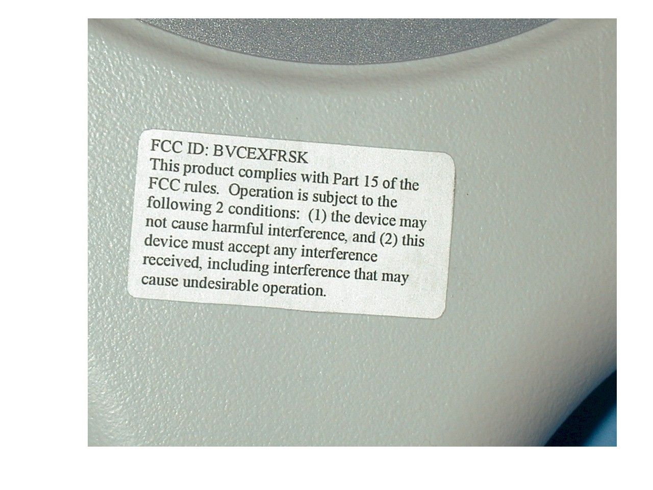
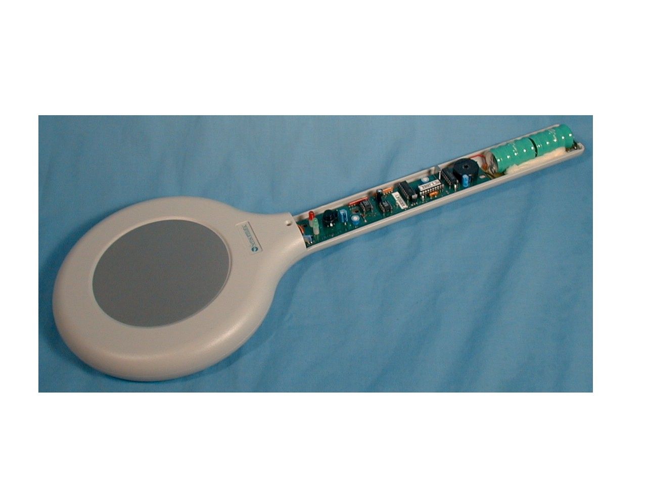
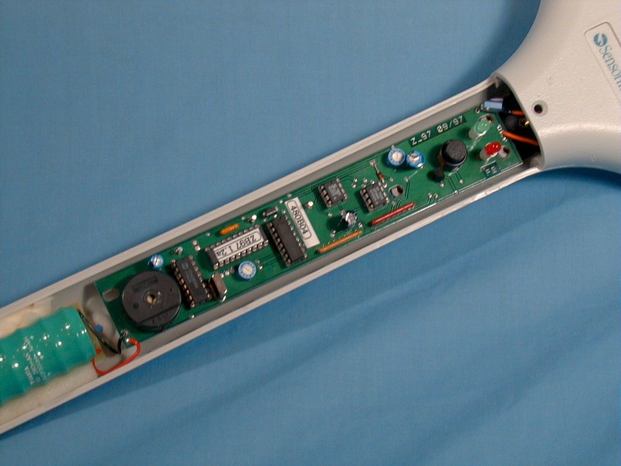
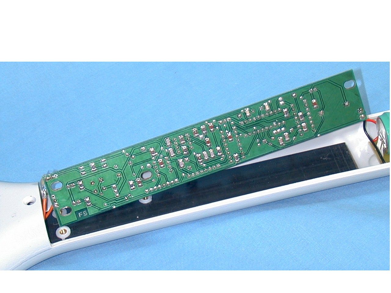
BVCEXFRSKLabel detector
Tyco Safety Products/Sensormatic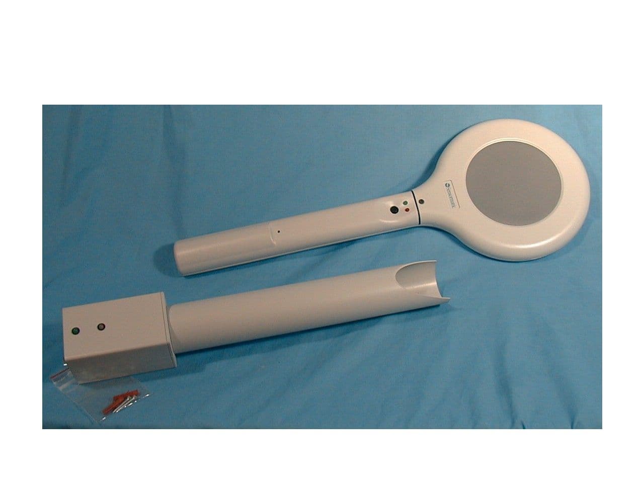
Click to zoom
Application Details
- Equipment Class
- FAP - Part 15 Anti-Pilferage Device
- Date of Grant
- May 18, 1999
- Application Purpose
- Original Equipment
- Date of Application
- Apr 04, 1999
- Equipment Note
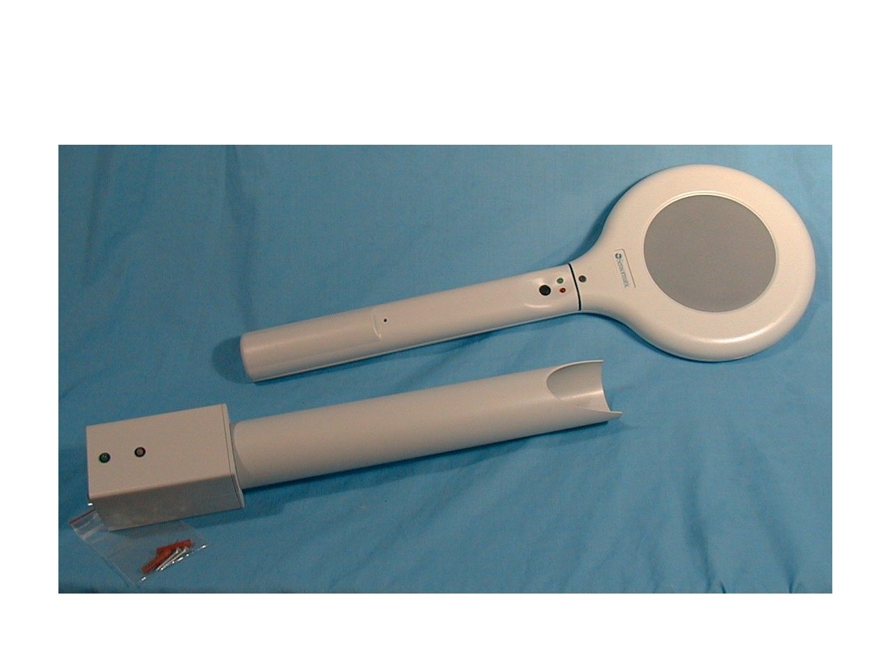
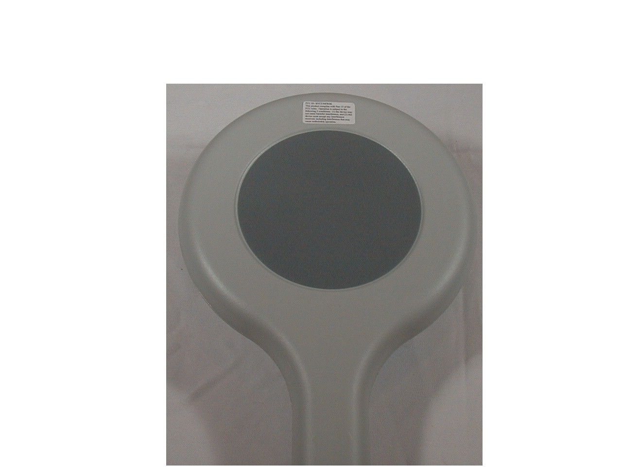
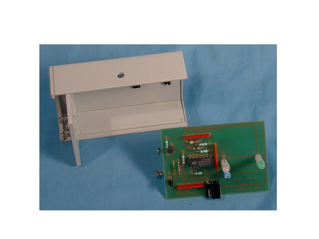
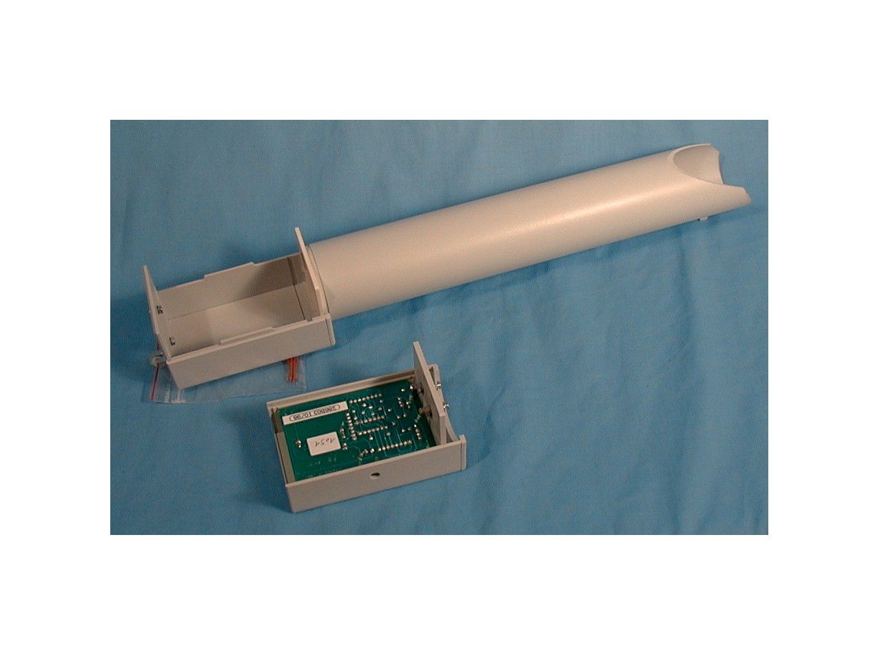
- Label detector
- Frequency Range
- 0.05800000 - 0.05800000
- Country
- United States
Documents & Files
Document Text
Text extracted from the exhibit documents filed with the FCC. Open a document above to read the original.
Users Manual
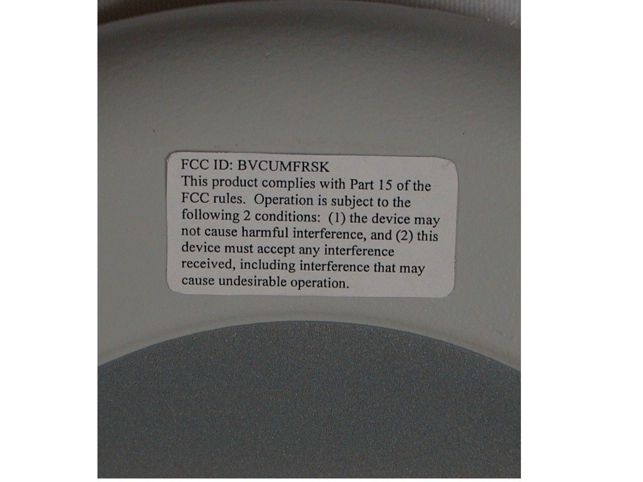
User’s Guide 8000-2668-01, Rev. A (2 pages) ULTRA•MAX EAS PRODUCTS1 1 11 1 Ultra•Max Ultra•MaxUltra•Max Ultra•Max Hand-Held Verifier Hand-Held VerifierHand-Held Verifier Hand-Held Verifier About the Unit About the UnitAbout the Unit About the Unit The Ultra•Max hand-held verifier is a battery- operated, rechargeable, device used to: • detect active Ultra•Max labels or tags at store exits so they can be returned to the checkout counter for proper deactivation or removal. • audit incoming merchandise for source tagging compliance. The verifier works by generating a short-range field and then listening for signal from an active Ultra•Max label or tag. If a signal is detected, the verifier alarms. The verifier consists of a: • Wand • Wall-mounted charger • Power supply Installing the Charger Installing the ChargerInstalling the Charger Installing the Charger IMPORTANT! To ensure installation complies with all applicable codes and regulations, install the charger exactly as follows: 1. Using two screws provided, mount charger vertically to any flat surface with its open end facing up (see diagram). 2. Plug cord of power supply into side of charger. 3. Plug power supply into an AC wall outlet. Green light on charger should light. Charging the Wand Charging the WandCharging the Wand Charging the Wand 1. With the lights on the wand facing you, slide handle of wand into tube of charger and push down. a. Top light on charger turns red to indicate charging, which can take up to 10 hours max. When top light turns green, wand is fully charged. Wand should be fully charged before using it for the first time. b. This product uses a nickel cadmium battery. To maximize battery life, fully discharge battery before recharging. c. Power supply may get slightly warm during charging (this is normal). 2. Remove wand from charger. Charge should last for about 5 hours. WARNING: Place wand in charger only for recharging, not for routine storage. If you want to use charger for storage, then unplug power supply when not recharging. Wand Charger Power Supply 2USER’S GUIDE ULTRA•MAX EAS PRODUCTS 8000-2668-01, REV. A Using the Wand Using the WandUsing the Wand Using the Wand You detect active labels and tags as follows: 1. Hold button on wand down. 2. The wand will go through an initialization routine (see below). 3. Continuing to hold the button down, move wand in a circular motion over item. If the red light on the wand glows and a steady beep occurs (with the green light remaining lit), then an active label or tag has been found. Initialization Routine Initialization RoutineInitialization Routine Initialization Routine The wand has a button, a buzzer, and two lights (red and green). When you first press down the button, the lights and buzzer go through a sequence as follows: a. Red flashes once b. Green flashes once c. Short beep occurs d. Green light glows steadily and remains on. The verifier is then ready to detect labels or tags. Note: Large metal surfaces can affect detection. The red light on the wand will blink when metal is detected; in which case, move the wand at least 1m (3') away from the metal and retry. If the green light blinks, then wand needs to be recharged. Specifications SpecificationsSpecifications Specifications AC power (N. America) .......120Vac, 1A (60Hz) Class 2 AC power (Europe) .............230Vac, 0.5A (50Hz) LPS Detection height ..................5cm to 10cm (2" to 4") Battery operating time .........5 hours Battery recharge time ..........10 hours max. Weight of wand ...................640g (22.6 oz) Weight of charger................240g (8.5 oz) Declarations DeclarationsDeclarations Declarations Regulatory Compliance Regulatory ComplianceRegulatory Compliance Regulatory Compliance EMC(wand & charger)........47 CFR, Part 15 I-ETS 300330 ETS 300683 Safety (power supply) ........Certified Class 2 EN60950 LPS Safety (wand & charger) ....EN60950 FCC COMPLIANCE: This equipment complies with Part 15 of the FCC rules for intentional radiators and Class A digital devices when installed and used in accordance with the instruction manual. Following these rules provides reasonable protection against harmful interference from equipment operated in a commercial area. This equipment should not be installed in a residential area as it can radiate radio frequency energy that could interfere with radio communications, a situation the user would have to fix at their own expense. EQUIPMENT MODIFICATION CAUTION: Equipment changes or modifications not expressly approved by Sensormatic Electronics Corporation, the party responsible for FCC compliance, could void the user's authority to operate the equipment and could create a hazardous condition. Other Declarations Other DeclarationsOther Declarations Other Declarations WARRANTY DISCLAIMER: Sensormatic Electronics Corporation makes no representation or warranty with respect to the contents hereof and specifically disclaims any implied warranties of merchantability or fitness for any particular purpose. Further, Sensormatic Electronics Corporation reserves the right to revise this publication and make changes from time to time in the content hereof without obligation of Sensormatic Electronics Corporation to notify any person of such revision or changes. LIMITED RIGHTS NOTICE: For units of the Department of Defense, all documentation and manuals were developed at private expense and no part of it was developed using Government Funds. The restrictions governing the use and disclosure of technical data marked with this legend are set forth in the definition of "limited rights" in paragraph (a) (15) of the clause of DFARS 252.227.7013. Unpublished - rights reserved under the Copyright Laws of the United States.
Block Diagram
The oscillator generate a tension of which frequency is about 58 kHz. The amplifier drive the coil and make the label to oscillate. The tension on the coil is about 150V peak to peak. The receiver is a amplifier and a pass-band filter of frequency about 58 kHz. It take the small signal of the coil (the oscillator is down) , amplify it to the detector. The detector transform a alternative signal to a continue signal. Only the envelop of the primary signal is interesting for the microprocessor. ZB001 Detector OP284 Amplifier L293B Receiver OP213 Microprocessor ST62T09 Oscillator CD4060 COIL Red LedGreen Led Buzzer The microprocessor make the oscillator on and then make it down. Then it make several measure of the detector. The result is ! nothing to do ! detection of a label ! inhibition :detection of a noisy signal (screen of a monitor for an example. ! synchronization : detection the emission of another Ultra-Max system. The microprocessor read also the battery tension, drive two lights and a buzzer. Ph0 : Emitting . The microprocessor make the oscillator and the amplifier on. Ph1 : Detecting . The microprocessor make the oscillator and the amplifier off. Then it measure the continue signal of the detector output. This value is to decide if a label is near. Ph2,Ph4, Ph6 : Synchronisation . Utra-Max system work with 50 Hz cycles or 75 Hz cycles. The Hand held Verifier cycle is 50 Hz. It need three phases to see the Utra-Max system presence. Ph5 : Inhibition. If the detector output is high, then it is a noisy signal and the first detection signal is not a label. The red light is blinking. 20 ms Ph6Ph5 Ph4 Ph2Ph1 Ph0
Block Diagram
The oscillator generate a tension of which frequency is about 58 kHz. The amplifier drive the coil and make the label to oscillate. The tension on the coil is about 150V peak to peak. The receiver is a amplifier and a pass-band filter of frequency about 58 kHz. It take the small signal of the coil (the oscillator is down) , amplify it to the detector. The detector transform a alternative signal to a continue signal. Only the envelop of the primary signal is interesting for the microprocessor. ZB001 Detector OP284 Amplifier L293B Receiver OP213 Microprocessor ST62T09 Oscillator CD4060 COIL Red LedGreen Led Buzzer Crystal 3.6864 MHz 57.6 kHz The microprocessor make the oscillator on and then make it down. Then it make several measure of the detector. The result is ! nothing to do ! detection of a label ! inhibition :detection of a noisy signal (screen of a monitor for an example. ! synchronization : detection the emission of another Ultra-Max system. The microprocessor read also the battery tension, drive two lights and a buzzer. Ph0 : Emitting . The microprocessor make the oscillator and the amplifier on. Ph1 : Detecting . The microprocessor make the oscillator and the amplifier off. Then it measure the continue signal of the detector output. This value is to decide if a label is near. Ph2,Ph4, Ph6 : Synchronisation . Utra-Max system work with 50 Hz cycles or 75 Hz cycles. The Hand held Verifier cycle is 50 Hz. It need three phases to see the Utra-Max system presence. Ph5 : Inhibition. If the detector output is high, then it is a noisy signal and the first detection signal is not a label. The red light is blinking. 20 ms Ph6Ph5 Ph4 Ph2Ph1 Ph0
Test Report
Test Summary For complete testing details, refer to Senton Report No. 51949-80919, included in the attachmen ProductUltra Max VerifierS/N: FCC IDBVCEXFRSK Date CompanySensormatic Electronics Corporation Proj LdrJohn Chamberlain Compliance EngDon Umbdenstock Test LocationSenton GmbH File No. Test PersonnelJohann Roidt Tests per 47CFR15.31, 15.35, 15.209 - October 1998; ANSI C63.4 -1992 Test site OATS Test distance10 meters Measurement Ant:1 meter elevation Signal Maximumdetermined by rotation of turntable and rotation of measurement antenna . turntable height.8 meters Test Item Description 58 kHz label detector (verifier), battery operated. Handle is inserted into a battery charger for charging. The verifier is non-operational during charging. April 11, 1999 Radiated Emissions Test Data Intentional Radiators: to 10th harmonic Frequency Senton Measured Value Conversion Factor, A to V Distance Correction Factor* Actual Value Limit Margin bw det MHzdBuA/mdBdBdBuV/mdBuV/m 58 28.451.5-59.120.832.3/30011.59 kHz peak 116 nfnf26.3/3009 kHz peak 174 nfnf22.8/3009 kHz peak 232 nfnf20.3/3009 kHz peak 290 nfnf18.4/3009 kHz peak 348 nfnf16.8/3009 kHz peak 406 nfnf15.4/3009 kHz peak 464 nfnf14.3/3009 kHz peak 522 nfnf33.3/309 kHz peak 580 nfnf32.3/309 kHz peak (Senton Report pgs 10 & 12) NOTES *: Square law is assumed, I.e. 40 dB/decade. DCF = 40 log (300/10) = -59.1 nf: noise floor Actual Value = Measured Value + Conversion Factor + Distance Correction Factor ts.
Test Report
Page !Syntax Error, ! of 33 Pages Straubing, November 24, 1998 T E S T - R E P O R T No. 51940-80919 for ZB 001 Hand Held Verifier Applicant:Sensormatic GmbH Purpose of testing:To show compliance with I-ETS 300 330 (December 1994) Product Class 1 Radio Equipment and Systems (RES); Short Range Devices (SRDs); Technical characteristics and test methods for radio equipment in the frequency range 9 kHz to 25 MHz and inductive loop systems in the frequency range 9 kHz to 30 MHz Note: The test data of this report relate only to the individual item which have been tested. This report shall not be reproduced except in full extent without the written approval of the testing laboratory. Report Form For Testing To I-ETS 300 330 Test Report No. 51940-80919 Page !Syntax Error, ! of 33 Pages Table of Contents 1.Identification of the Test Laboratory........................................................... 3 2.Administrative Data.................................................................................... 4 3.Deviations from the Test Specifications..................................................... 6 4.Summary of Test Results........................................................................... 7 5.Additional References................................................................................ 8 6.Test Results ............................................................................................... 9 7.Test Equipment and Ancillaries used for Tests........................................ 14 8.Measurement Uncertainty Values ............................................................ 18 9.Photographs of the Equipment Under Test.............................................. 21 10. Additional Information supplementary to the Test Report ........................ 33 Report Form For Testing To I-ETS 300 330 Test Report No. 51940-80919 Page !Syntax Error, ! of 33 Pages 1.Identification of the Test Laboratory DETAILS OF THE TEST LABORATORY COMPANY NAME:Senton GmbH EMI/EMC Test Center ADDRESS:Aeussere Fruehlingstrasse 45 D-94315 Straubing Germany LABORATORY ACCREDITATION:DAR-Registration No. TTI-P-G 062/94-30 DAR-Registration No. TTI-P-G 109/95-20 NAME FOR CONTACT PURPOSES:Mr. Johann Roidt TELEPHONE: (+49) 09421 55 22-0FAX: (+49) 09421 55 22 99 PERSONNEL INVOLVED IN THIS TEST REPORT TECHNICAL DIRECTOR: ............................................................. Mr. Johann Roidt RESPONSIBLE FOR TESTING: ............................................................. Mr. Thomas Eberl RESPONSIBLE FOR TEST REPORT:Mr. Thomas Eberl Report Form For Testing To I-ETS 300 330 Test Report No. 51940-80919 Page !Syntax Error, ! of 33 Pages 2.Administrative Data IDENTIFICATION OF EUT TYPE DESIGNATION OF EUT (i.e. system if EUT consists of more than one part): ZB 001 PARTS OF THE SYSTEM (including appropriate type designations) 1 SERIAL NUMBER(S):-- FREQUENCY RANGE:1 kHz - 135 kHz (according to BAPT 222 ZV 122) OPERATING FREQUENCY:57.6 kHz CHANNEL SPACING:-- ITU DESIGNATION:1H00 NON NUMBER OF RF-CHANNELS: NUMBER OF CONTROL FUNCTIONS: POWER SUPPLY:Accu 12 V TYPE OF ANTENNA:Printed antenna SIZE / LENGTH OF ANTENNA:0.0176 m² INTERFACE(S):-- Report Form For Testing To I-ETS 300 330 Test Report No. 51940-80919 Page !Syntax Error, ! of 33 Pages ADMINISTRATIVE DATA APPLICANT (full address):Sensormatic GmbH Am Schimmersfeld 7 40880 Ratingen ( Germany ) CONTACT PERSON:Mr. Zinke TELEPHONE NO.:02102/431326 FAX NO.:02102/431250 RECEIPT OF EUT:Oct. 98 DATE(S) OF TEST:Nov. 98 VERSION OF EUT:series version NOTE: Report Form For Testing To I-ETS 300 330 Test Report No. 51940-80919 Page !Syntax Error, ! of 33 Pages 3.Deviations from the Test Specifications All tests were performed without deviations from the test specifications. Report Form For Testing To I-ETS 300 330 Test Report No. 51940-80919 Page !Syntax Error, ! of 33 Pages 4.Summary of Test Results REFERENCE FOR PERFORMED TESTS Reference:I-ETS 300 330 (December 1994) Title:Radio Equipment and Systems (RES); Short Range Devices (SRDs); Technical characteristics and test methods for radio equipment in the frequency range 9 kHz to 25 MHz and inductive loop systems in the frequency range 9 kHz to 30 MHz Result:The tested sample fully complies with the requirements set forth in I-ETS 300 330 (December 1994) for equipment belonging to product class 1 LIST OF MEASUREMENTS Sub- clause Parameter to be measuredTestPage Transmitter parameters 7.2.1H-field (Class 1)Passed 7.2.2RF carrier current (Classes 2 and 3)Not applicable 7.2.3Radiated E-field (Class 4)Not applicable 7.3.2Frequency errorNot applicable 7.3.3Modulation bandwidthPassed 7.4.2.1 7.4.2.2 Spurious emissions conducted - transmitter operatingNot applicable 7.4.2.1 7.4.2.2 Spurious emissions conducted - transmitter on standbyNot applicable 7.4.3 7.4.4 Spurious emissions radiated - transmitter operatingPassed 7.4.3 7.4.4 Spurious emissions radiated - transmitter on standbyNot applicable Report Form For Testing To I-ETS 300 330 Test Report No. 51940-80919 Page !Syntax Error, ! of 33 Pages 5.Additional References ADDITIONAL REFERENCES [ X ]The EUT meets the requirements of BAPT 222 ZV 122 []The EUT complies with performance specification MPT 1337 published by Radiocommunications Agency []The EUT complies with performance specification MPT 1339 published by Radiocommunications Agency Report Form For Testing To I-ETS 300 330 Test Report No. 51940-80919 Page !Syntax Error, ! of 33 Pages 6.Test Results Report Form For Testing To I-ETS 300 330 Test Report No. 51940-80919 Page !Syntax Error, ! of 33 Pages Ambiente temperature: +20.0 ° CRelative humidity: 50 % H-FIELD FIELD STRENGTHSUBCLAUSE 7.2.1 (CLASS 1) Rated field strength (maximum) 28.4 dBμA/m at 10 metresAntenna size 0.0176 m² Test conditions Transmitter field strength (dBμA/m) CH 1CH 2CH 3 T nom +20.0 ° C V nom 12.0 V28.4---- Maximum deviation from rated output under normal test conditions (dB) 1.5 Measurement uncertainty (dBμA/m)± 3 LIMIT:SUBCLAUSE 7.2.1.3 Frequ…
Text truncated - open the document above for the full version.
Test Report
Sensormatic Electronics Corporation Conducted Emissions Test 1 Project Name Verifier – Conducted Emissions Test Location Sensormatic Elec Corp. Boca Raton, FL 33431 EUT Name Verifier w/120VAC adapter Serial Number N/A Engineer John Chamberlin Phone Number Date of Test 4/20/99 7:11:38 AM Test Name Conducted Emissions Compliance Tech Compl. Eng Steve Krizmanich Don Umbdenstock Rules 47CFR15.207, ANSI C63.4 1992 Comments Verifier 120VAC xfmr: AC-DC Adapter Type:NE101/01138M Prim: 110VAC 50/60Hz Sec: 15.5VDC 30Ma Test Voltage 120 V Wand was completely discharged prior to insertion into charger, thus insuring maximum charge current. 15.207 rules specify testing between 0.45 and 30 MHz. As seen below, the band of interest includes only noise floor. Figure 1. L1 Full Range Sensormatic Electronics Corporation Conducted Emissions Test 2 Figure 2. L2 Full Range Equipment Used: Spectrum Analyzer HP8591EM S/N 3649A01066 Line Impedance Stabilization Network EMCO 3816/2NM S/N 1018
Contact Information
Applicant
Mark D. Alexis(Manager Regulatory Compliance)
Test Firm
TUV SUD Product Service GmbH PS-EMC-STRRainer Heller
Technical Specifications
| # | Rule Parts | Frequency Range | Power Output | Emission |
|---|---|---|---|---|
| 1 | 15C | 0.058 MHz - 0.058 MHz | - | NON |
Other Applications from Tyco Safety Products/Sensormatic

BVCIDX5000
Jun 23, 2026UHF RFID Reader
Equipment Class
DSS - Part 15 Spread Spectrum TransmitterBVCAMS1137H
Dec 22, 2025Anti Theft System - Electronic Asset Security
Equipment Class
FAP - Part 15 Anti-Pilferage DeviceBVCAMB9012
Sep 10, 2024Label Deactivator Controller
Equipment Class
DCD - Part 15 Low Power Transmitter Below 1705 kHz
BVC-4000-PI26
Sep 24, 2015RM2L-4000-P126, RM2-4000-P126
Equipment Class
DXX - Part 15 Low Power Communication Device Transmitter
BVCAMS90604
May 20, 2014Anti-pilferage Device
Equipment Class
FAP - Part 15 Anti-Pilferage Device