BVCHH2BCSSPREAD SPECTRUM TRANSMITTER
Tyco Safety Products/Sensormatic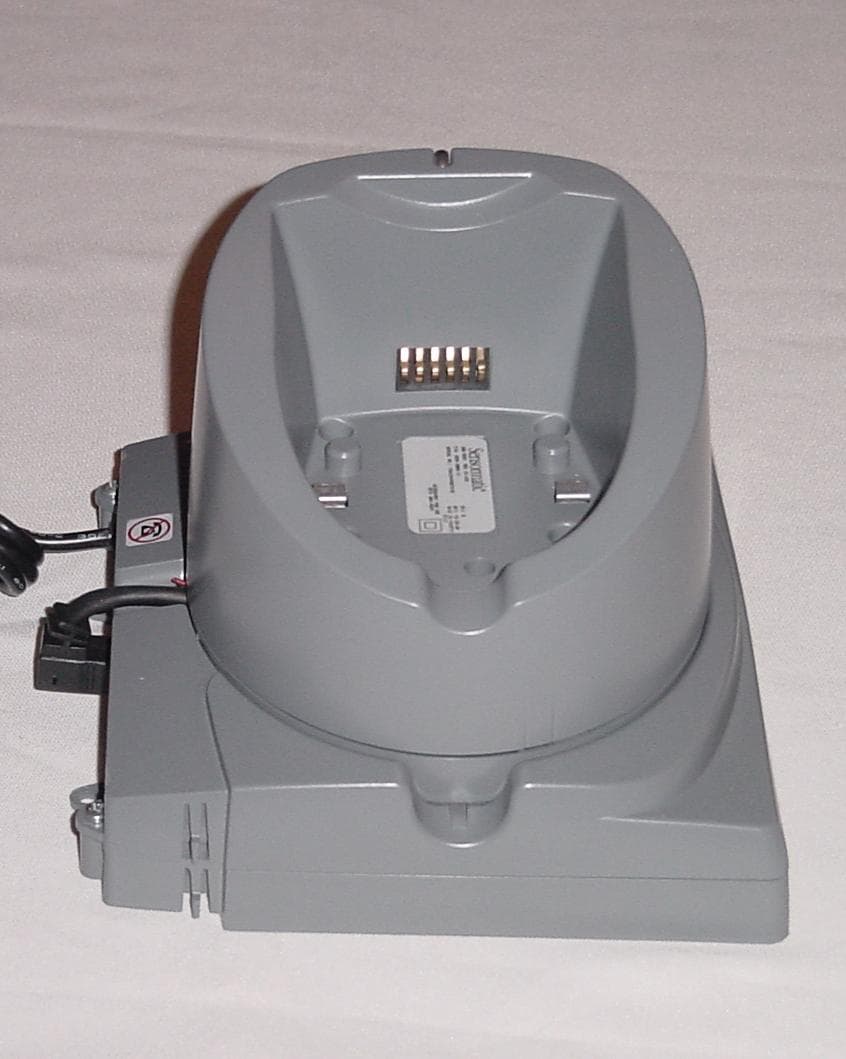
Click to zoom
Application Details
- Equipment Class
- DSS - Part 15 Spread Spectrum Transmitter
- Date of Grant
- Feb 07, 2005
- Application Purpose
- Original Equipment
- Date of Application
- Feb 07, 2005
- Equipment Note
- SPREAD SPECTRUM TRANSMITTER
- Frequency Range
- 903.20000000 - 914.80000000
- Country
- United States
Documents & Files
Document Text
Text extracted from the exhibit documents filed with the FCC. Open a document above to read the original.
Users Manual
AMB-4020 HAND-HELD SCANNER/DEACTIVATOR 8200-0369-04, REV. A USER’S GUIDE 1 of 9 AMB-4020 Hand-Held Scanner/Deactivator User’s Guide Product Overview The AMB-4020 hand-held scanner/deactivator is a multi-purpose device used for scanning barcodes, detecting and deactivating EAS labels, alarm logging, and source tagging compliance checking. It includes the following features: © 2004 Sensormatic Electronics Corp. Feature Function Base Charging Station with security lock Secures the hand-held unit when not in use. Keeps unit batteries optimally charged. Liquid Crystal Display Displays prompts and messages relating to the task at hand. Keypad Used for entering information. See the Keypad Overview for details. LED indicators Red and green lights indicate proper unit function. Integrated Barcode Scanner Used to scan barcodes on receipts, merchandise, packages and badges. Ergonomic Grip Provides comfortable use for a variety of users. Feature Function Integrated EAS Detector / Deactivator Assists in identifying merchandise that has not been properly deactivated at the point-of-sale. Also allows these items to be deactivated with proof of purchase. Scanner Trigger Activates the scanner when needed. Alternate Scan Barcode button Activates the barcode scanner when the unit is stored in its base. WARNING: Before using this device, read this manual carefully! Ensure that all the safety instructions specified within this manual are continuously observed and respected during the installation and/or during the operation of this device. Liquid Crystal Display (LCD) LED indicators Integrated Detector/Deactivator Scanner Trigger (beneath keypad) Base Charging Station Ergonomic Grip Keypad Alternate Scan Barcode Button WARNING! Laser aperture- laser beam Integrated Barcode Scanner AMB-4020 HAND-HELD SCANNER/DEACTIVATOR 8200-0369-04, REV. A USER’S GUIDE 2 of 9 Keypad Overview F1 F2 F3 F4 F5 F6 1 pqrs 7 9 wxyz 3 def 4 ghi abc 2 jkl 5 tuv 8 6 mno 0 The buttons on the keypad allow you enter information about the activity being performed. Depending upon the software configuration, some keypad features may not be available. Button Function Power Switches the scanner/deactivator to standby mode to conserve power. Cursor Moves the cursor around the LCD. Press an arrow corresponding to the direction that you want to move the cursor. Enter Makes selections appearing on the LCD. Alternate Scan Barcode Activates the barcode scanner when the unit is stored in the base. Button Function Backlighting Turns on LCD backlighting if the display appears dark. Alpha Shift Key Toggles between entering numbers and alphabetic characters using the numeric keypad. F1 F2F3 F4 F5F6 Function Keys Special purpose keys that can be programmed to perform specific functions depending upon the screen displayed. 1 pqrs 7 9 wxyz 3 def 4 ghi abc 2 jkl 5 tuv 8 6 mno 0 Numeric Keypad Allows numbers to be manually entered. Alphabetic characters can be entered using these buttons and by pressing the Alpha Shift key. Function Keys (F1 – F6) Numeric Keypad (0 – 9) Power Cursor Control (Up/Down/Left/Right) LCD Backlighting Enter Alternate Scan Barcode LCD Alphanumeric Shift Key AMB-4020 HAND-HELD SCANNER/DEACTIVATOR 8200-0369-04, REV. A USER’S GUIDE 3 of 9 Contents Before Using the AMB-4020 Scanner/Deactivator3 Safe Operation................................................3 Laser Device Warnings...................................3 Avoid Dropping the Scanner/Deactivator.......3 Preparing the Scanner/Deactivator.......................4 Charging and Securing the Scanner/Deactivator.......................................4 Removing the Scanner/Deactivator from the Base Charging Station....................................4 Using the Scanner/Deactivator.............................5 Scanning Barcodes.........................................5 Detecting/Deactivating EAS Tags and Labels6 Logging Alarms...............................................6 Maintenance..........................................................6 Glossary................................................................6 Specifications........................................................7 Hand-Held Scanner/Deactivator.....................7 Base Charging Station....................................8 Declarations..........................................................9 Before Using the AMB-4020 Scanner/Deactivator Keep the following precautions in mind when using the AMB-4020 hand-held scanner/ deactivator. Safe Operation IMPORTANT! This device may be used to locate and deactivate Ultra•Max ® labels on merchandise to help speed up the checkout process in busy retail environments. Like many similar devices, the AMB- 4020 scanner/deactivator emits electromagnetic fields that may affect certain implanted medical devices. Since it is impossible to tell which customers may have an implanted medical device, it should not be used within 30cm (12in) of a customer’s head and torso. Some employees with implanted medical devices may notice interactions while operating this equipment. These interactions are ordinarily transitory and should not be harmful. However, if the employee feels uncomfortable, a change in assigned duties should be considered. Laser Device Warnings WARNING: Do not stare (look) in the beam of the laser: It is a Laser Class 2 and it may produce eye damages. WARNING: Do not test the device with the aperture directed to your eyes. WARNING: It is very important to be aware that the duration of the laser radiation emission is longer than the audible beep that results when the push- button (trigger) is activated: DO NOT ATTEMPT TO TURN THE APERTURE TOWARDS YOUR EYES DURING THE RADIATION EMISSION. The red beam is an optical indicator that the radiation is present and, as long as it is visible, the scanner shall not be directed towards the operator or towards any other person’s eyes. WARNING: Do not attempt to open the equipment enclosure! There are no serviceable parts within this equipm…
Text truncated - open the document above for the full version.
Cover Letter(s)
Sensormatic Electronics Corporation 6600 Congress Avenue, Boca Raton, FL 33487 Telephone (561) 912-6000 FAX (561) 912-6787 January 25, 2005 Timco Engineering, Inc. 849 N.W. State Road 45 P.O. Box 370 Newberry, Florida 32669 USA Re: Request for withholding from public disclosure proprietary information submitted pursuant to an application for certification of transmitter. FCC ID: FCC ID: BVCHH2BCS Dear Sir or Madam: Sensormatic Electronics Corporation requests certain materials submitted with this application for certification be withheld from public disclosure. This request is made under the provision of 47 CFR 0.457 (d) and 5 USC 552(b)(4) Freedom of Information Act, Trade Secrets. The items for which confidentiality is requested include the Operational Description, Block Diagram and Schematic Diagrams. This information contains proprietary information (trade secrets) regarding the circuit operation and capabilities (specific values of components, circuit design details and system architecture) that are the result of our extensive investment in research and development. Without the disclosed information, competitive organizations would take considerable more time to assess and develop a workable competitive product. As a result, we believe that disclosure of these company-guarded materials would compromise our leading position in this market. We therefore formally request that the materials identified “Confidential” be kept strictly confidential and not made available for inspections by any other party, except on a need to know basis for the sole purpose of the certification process. Sincerely, William M. Elliott Sr. EMC Engineer, Compliance Engineering
External Photos
Exhibit 6 FCC ID: BVCHH2BCS IC: 3506A-HH2BCS AMB-4020 Base Charging Station External Photos External Photo 1 – AMB-4020 Base Charging Station Side View Exhibit 6 FCC ID: BVCHH2BCS IC: 3506A-HH2BCS External Photo 2 – AMB-4020 Base Charging Station Front View Exhibit 6 FCC ID: BVCHH2BCS IC: 3506A-HH2BCS External Photo 3 – AMB-4020 Base Charging Station Rear View
ID Label/Location Info
Exhibit 2 FCC ID: BVCHH2BCS IC: 3506A-HH2BCS AMB-4020 Base Charging Station Label Artwork Model: AMB-4020 REG ID: BCS P/N: 0304-2854-01 MFD: 09/04 SERIAL NO: SECA0117012345 REV : A FCC ID: BVCHH2BCS This device complies with part 15 of the FCC rules. Operation is subject to the following two conditions: (1) this device may not cause harmful interference, and (2) this device must accept any interference received, including interference that may cause undesired operation. This class a digital apparatus complies with Canadian ICES-003. Cet appareil numérique de la classe a est confrome á la norme NMB-003 du Canada. IC:3506A-HH2BCS MADE IN Puerto Rico
Internal Photos
Exhibit 7 FCC ID: BVCHH2BCS IC: 3506A-HH2BCS AMB-4020 Base Charging Station Internal Photos Internal Photo 1 – Base Charger PCB Top View Exhibit 7 FCC ID: BVCHH2BCS IC: 3506A-HH2BCS Internal Photo 2 – Base Charger PCB Bottom View Exhibit 7 FCC ID: BVCHH2BCS IC: 3506A-HH2BCS Internal Photo 3 – Base Communications PCB Top View Exhibit 7 FCC ID: BVCHH2BCS IC: 3506A-HH2BCS Internal Photo 4 – Base Communications PCB Bottom View Exhibit 7 FCC ID: BVCHH2BCS IC: 3506A-HH2BCS Internal Photo 5 – Base Interconnect PCB Bottom View Exhibit 7 FCC ID: BVCHH2BCS IC: 3506A-HH2BCS Internal Photo 6 – Base Interconnect PCB Top View
Test Report
FCC ID: BVCHH2BCS IC: 3506A-HH2BCS 1 COMPANY Sensormatic Electronics Corp. 6600 Congress Ave Boca Raton, Florida 33487 PRODUCT TESTED Sensormatic® AMB-4020 Base Charging Station FCC ID: BVCHH2BCS IC: 3506A-HH2BCS FCC RULES 15.207, 15.209, 15.247 TEST DATE December 8, 2004 – January 31, 2005 SUBMITTED BY William M. Elliott FCC ID: BVCHH2BCS IC: 3506A-HH2BCS 2 INDEX I. SUMMARY OF RESULTS 3 2. GENERAL INFORMATION 4 Test Methodology / System Description 4 Test Facility 5 2I. FREQUENCY HOPPING REQUIREMENTS, 15.247 6 Pseudorandom Frequency Hopping Sequence 6 Equal Hopping Frequency Use 6 DeFacto EIRP Limit 6 System Receiver Input Bandwidth 6 System Receiver Hopping Capability 7 RF Exposure Compliance Information 8 IV. LIST OF MEASUREMENT EQUIPMENT 10 V. DATA 11 Input Voltage Variation 11 AC Conducted Emissions 12 Carrier Frequency Separation 13 Number of Hopping Channels 14 Dwell Time 15 20 dB Bandwidth 16 Peak Power 17 Band Edge Compliance of RF Conducted Emissions 18 Spurious RF Conducted Emissions 19 Spurious Radiated Emissions 22 Fundamental Measurement 22 Spurious Emissions Above 1 GHz 23 Spurious Emissions Below 1 GHz / ERP 24 Digital Emissions 25 FCC ID: BVCHH2BCS IC: 3506A-HH2BCS 3 I. Summary of Results FCC 47 CFR Part [RSS 210 Section] Testing Requirement Test Limits Issues /Comments 15,15 (b) User Accessible Controls N/A The product contains no user accessible controls that increase transmission power above permitted levels. 15.31(e) Vary Input Power N/A Input was varied from 102 to 138 V AC. Input power to antenna was measured. 15.109 [IC 7.3] Radiated Emissions Requirements [Digital Device] See Table 15.109. Unintentional digital emissions subject to Class A limits. Digital emissions determined by turning transmitter off. Complies [Verification]. 15.203 Antenna Requirements Permantantly attached or unique coupling. The TX antenna is a quarter wave PCB trace antenna Complies. 15.207 (a) (b) [IC 6.6] AC Power Line Conducted Measurements CISPR Class B Limits Conducted emissions on AC side of DC supply is provided in this report. Complies. 15.205 (a) (b) [IC 6.3] 15.209 [IC 6.2.2(o)(e1)] Restricted Band Compliance Must comply with limits Specified in 15.209 (a) The fundamental is not in a restricted band and the spurious emissions in the restricted bands comply with the general emission limits found in 15.209. 15.247 (a) (1) [IC 6.2.2(o)(a1)] Carrier Frequency Separation Separated by minimum of 25 kHz or 20 dB BW of the hopping channel, whichever is greater. The carrier frequencies are separated by at least the 20 dB BW of the hopping channel. Complies. 15.247 (a) (1) (i) [IC 6.2.2(o)(a2)] Number of Hopping Frequencies – 900 MHz TX If 20 dB BW is < 250 kHz, then shall use at least 50 hopping channels. The EUT has 60 hopping channels and complies with the requirement. 15.247 (a) (1) (i) [IC 6.2.2(o)(a2)] Dwell Time – Number of Hopping Frequencies >= 50 < 0.4 sec within a 20 second period The EUT complies with the requirement. See attached data. 15.247 (a) (1) (i) [IC 6.2.2(o)(a2)] Maximum 20dB Bandwidth Maximum 20 dB BW of the hopping channel cannot exceed 500 kHz. The EUT complies with the requirement. 15.247 (b) (2) (3) [IC 6.2.2(o)(a2)] Output Power 902-928 MHz Tx < 1 W – freq. hopping with 50 channels The EUT complies with the requirement. 15.247 (b) (4) Maximum Antenna Gain If directional gain of transmitting antenna greater than 6 dBi, the peak output power of the device shall be reduced below the stated values in 15.247 (b) (2) and b (3) The permantly attached antenna used with the device has a gain < 6 dBi. 15.247 (b) (5) [IC Section 14] RF Exposure Must ensure that RF MPE to the public falls within Commission Guidelines See RF Exposure Exhibit. 15.247 c [IC 6.2.2(o)(e1)] Band-edge Compliance of RF Emissions In any 100 kHz bandwidth outside the frequency band in which the spread spectrum intentional radiator is operating, the radio frequency power that is produced by the intentional radiator shall be at least 20 dB below that in the 100 kHz bandwidth within the band that contains the highest level of the desired power The EUT complies with the band-edge requirements. No band-edge emissions fall within restricted bands. See submitted data. 15.247 c [IC 6.2.2(o)(e1)] Radiated Restricted Band Emissions Requirements Must comply with limits Specified in 15.209 (a) The spurious emissions in the restricted bands from this device comply with the emission limits found in 15.209. 15.247 (g) (h) See appropriate sections of report. FCC ID: BVCHH2BCS IC: 3506A-HH2BCS 4 II. General Information This report is part of the application for Certification of a 900 MHz Frequency-Hopping Spread Spectrum transmitter operating in the 902-928 MHz bands under the rules provided for frequency-hopping spread spectrum transmitters found in 47 CFR 15.247. The product covered by this report is the Sensormatic AMB-4020 Base Charging Station. Test Methodology The Sensormatic® AMB-4020 Base Charging Station charges the lithium-ion battery of the Sensormatic® AMB-4020 Hand-Held Scanner/Deactivator and locks the handheld securely in place when not in use. The Base Charging Station also has circuitry that enables it to communicate over a wired Ethernet network namely 10BaseT. It contains an RS232 port for service only and an RS485 port that can communicate with other EAS systems and an I/O connector that can sense relay contact closures is used in some legacy EAS systems instead of RS485. A 903 to 915 MHz frequency hopping transmitter is also contained in this module and is used to wirelessly transmit the zero crossing line sync for the purpose of synchronizing the Hand-Held Scanner/Deactivator unit that is equipped with an equivalent receiver. The frequencies as well as the output power settings are programmed from the DSP to the UHF TX via the 3 wire SPI interface. This UHF transmitter hops through a random sequence of 60 frequencies between 903 and 915MHz, spending approx 340ms on each frequency. Once the TX has…
Text truncated - open the document above for the full version.
Test Setup Photos
Exhibit 10 FCC ID: BVCHH2BCS IC: 3506A-HH2BCS Test Setup Photos Conducted Emissions Exhibit 10 FCC ID: BVCHH2BCS IC: 3506A-HH2BCS Radiated Emissions
Contact Information
Applicant
Mark D. Alexis(Manager Regulatory Compliance)
Test Firm
Sensormatic Electronics CorporationWilliam Elliott
Technical Specifications
| # | Rule Parts | Frequency Range | Power Output |
|---|---|---|---|
| 1 | 15C | 903.2 MHz - 914.8 MHz | 32.00 mW |
Other Applications from Tyco Safety Products/Sensormatic

BVCIDX5000
Jun 23, 2026UHF RFID Reader
Equipment Class
DSS - Part 15 Spread Spectrum TransmitterBVCAMS1137H
Dec 22, 2025Anti Theft System - Electronic Asset Security
Equipment Class
FAP - Part 15 Anti-Pilferage DeviceBVCAMB9012
Sep 10, 2024Label Deactivator Controller
Equipment Class
DCD - Part 15 Low Power Transmitter Below 1705 kHz
BVC-4000-PI26
Sep 24, 2015RM2L-4000-P126, RM2-4000-P126
Equipment Class
DXX - Part 15 Low Power Communication Device Transmitter
BVCAMS90604
May 20, 2014Anti-pilferage Device
Equipment Class
FAP - Part 15 Anti-Pilferage Device