BVCIDR3000RF ID Reader
Tyco Safety Products/Sensormatic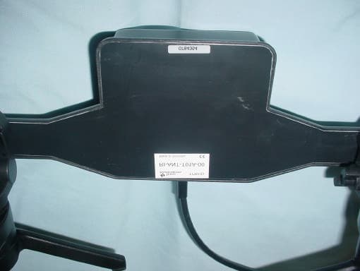
Click to zoom
Application Details
- Equipment Class
- DXX - Part 15 Low Power Communication Device Transmitter
- Date of Grant
- Mar 31, 2003
- Application Purpose
- Original Equipment
- Date of Application
- Mar 31, 2003
- Equipment Note
- RF ID Reader
- Frequency Range
- 13.56000000 - 13.56000000
- Country
- United States
Documents & Files
Document Text
Text extracted from the exhibit documents filed with the FCC. Open a document above to read the original.
Users Manual
RFID READER MODEL IDR-3000 INSTALLATION AND SERVICE GUIDE (8200-0222-02, REV. 1/A) 1 of 9 RFID Reader Model IDR-3000 Installation and Service Guide The Model IDR-3000 RFID Reader uses RFID (radio frequency identification) technology to read data stored on RFID tags and labels. The RFID Reader operates as an SQL (structured query language) server, providing tag data in response to requests from another application. A separate software application may be used to direct its operation and provide a user interface. The RFID Reader supports UHF (ultra high frequency) and HF (high frequency) antennas which are available separately. The reader provides two UHF and two HF antenna ports and transfers data to a computer through an Ethernet port. Contents About this Guide .................................................... 1 Before You Begin................................................... 1 Installation.............................................................. 3 Service ................................................................... 5 Specifications......................................................... 8 Declarations ........................................................... 9 © Sensormatic 2003 About this Guide This installation and service guide explains how to install the Model IDR-3000 RFID Reader and use the browser-based interface. Use the instructions provided with the antennas to install and service the antennas. If you need assistance... Call the RFID support line at 1-800-543-9740. Before You Begin Installation Requirements • The RFID reader is shipped with a certified limited power source with a cable length of 1.8m (6ft). • Use only authorized antennas and cables to maintain FCC approval (see Authorized Antennas on page 2). • In order to comply with FCC requirements for RF exposure safety, a separation distance of at least 22cm (8.7in.) needs to be maintained between the radiating elements of the antenna and the bodies of nearby persons. • Antennas must be mounted within 3.6m (12ft) cable distance of the reader. • Provide strain relief for all reader connections. • A shielded Ethernet cable must be used to communicate with other devices. • Multiple readers and antennas can be used in combination to enhance detection at specific locations provided the software application is able to synchronize antenna operation. Performance Considerations RFID reader performance may be affected by external factors including: • Tag variables • Environment Performance tests conducted under typical operating conditions at your site are recommended to help you optimize system performance. RFID READER MODEL IDR-3000 INSTALLATION AND SERVICE GUIDE (8200-0222-02, REV. 1/A) 2 of 9 Tag Variables There are several variables associated with tags that can affect reader performance: • Application surface — Some materials interfere with tag performance including metal and moisture. Tags applied to items made from or containing these materials may not perform as expected. • Tag orientation — Reader performance is affected by the orientation of the tag in the antenna field. • Tag model — many tag models are available. Each model has its own performance characteristics. Environment RFID Reader performance may be affected by the following: • Metal surfaces such as desks, filing cabinets, book shelves, and waste baskets may enhance or degrade reader performance. Mount antennas as far as possible from metal surfaces that are adversely affecting system performance. • Devices that operate at 900MHz such as cordless phones or wireless LANs can interfere with reader performance. These devices may degrade performance of the reader. The reader may also adversely affect performance of the 900MHz device. • Antennas operating in close proximity may interfere with one another, degrading reader performance. Interference from other antennas may be eliminated or reduced by using either one or both of the following strategies: − Affected antennas may be synchronized by a separate user application using a time- multiplexing strategy. − Antenna power can be reduced by reconfiguring the RF Transmit Power setting for the reader. Authorized Antennas IDANTM1000-915L IDANTM1000-915L is a linear polarized antenna that reads data from 915MHz tags. It has a read range of up to 3.6m (12ft) from the antenna. Coverage area of up to 7.3m (24ft) may be achieved by using two antennas, one on each side of the opening. The antenna is shipped with 3.6m (12ft) of cable and an appropriate connector for the RFID reader. A mounting bracket suitable for attaching the antenna to a standard 1/4 inch–20 thread stud is included. IDANTM1000-915C IDANTM1000-915C is a circular polarized antenna that reads data from 915MHz tags. It has a read range of up to 1.8m (6ft) from the antenna. Coverage area of up to 3.6m (12ft) may be achieved by using two antennas, one on each side of the opening. The antenna is shipped with 3.6m (12ft) of cable and an appropriate connector for the RFID reader. A mounting bracket suitable for attaching the antenna to a standard 1/4 inch–20 thread stud is included. RFID READER MODEL IDR-3000 INSTALLATION AND SERVICE GUIDE (8200-0222-02, REV. 1/A) 3 of 9 IDANTM1000-1356T IDANTM1000-1356T reads data from 13.56MHz tags. It has a read range of up to 0.3m (1ft.) from the antenna. Coverage area of up to 0.6m (2ft) may be achieved by using two antennas, one on each side of the opening. The antenna is shipped with 3.6m (12ft) of cable and an appropriate connector for the RFID reader. A mounting bracket suitable for attaching the antenna to a standard 1/4 inch–20 thread stud is included. IDANTM1000-1356P IDANTM1000-1356P reads data from 13.56MHz tags. It has a read range of up to 0.3m (1ft.) from the antenna. Coverage area of up to 0.6m (2ft) may be achieved by using two antennas, one on each side of the opening. The antenna is shipped with 3.6m (12ft) of cable and an appropriate connector for the RFID reader. Mounting Hardware Mounting…
Text truncated - open the document above for the full version.
Cover Letter(s)
February 3, 2003 Curtis-Straus LLC 527 Great Road Littleton, MA 01460 USA Re: Request for withholding from public disclosure proprietary information submitted pursuant to an application for certification for a low power transmitter. FCC ID: BVCIDR3000 Dear Sir or Madam: Sensormatic Electronics Corporation requests certain materials submitted with this application for certification of device FCC ID: BVCIDR3000 be withheld from public disclosure. This request is made under the provision of 47 CFR 0.457 (d) and 5 USC 552(b)(4) Freedom of Information Act, Trade Secrets. The items for which confidentiality is requested include the Operational Description, Block Diagram, Schematic Diagrams and any listing of components such as a Bill of Material. This information contains proprietary information (trade secrets) regarding the circuit operation and capabilities (specific values of components, circuit design details and system architecture) that are the result of our extensive investment in research and development. Without the disclosed information, competitive organizations would take considerable more time to assess and develop a workable competitive product. As a result, we believe that disclosure of these company- guarded materials would compromise our leading position in this market. We therefore formally request that the materials identified “Confidential” be kept strictly confidential and not made available for inspections by any other party, except on a need to know basis for the sole purpose of the certification process. Sincerely, Donald J. Umbdenstock Sr. Principal Engineer, Compliance Engineering
Cover Letter(s)
From: "Curtis-Straus Certification Dept." <[email protected]> To: "Mike Buchholz" <[email protected]> Sent: Tuesday, March 25, 2003 1:37 PM Sub ject: Sensormatic FCC ID: BVCIDR3000 TCB findings Page 1 of 1 4/1/2003 Hi Mike, Our reviewers have identified the following issues: 1. The two test reports supplied did not include issue dates. 2. Please provide a manufacturers datasheets for the shelf antenna and ICode 9910 antenna. 3. The 15.247 test report states the circularly polarized patch antenna has a gain of 6dBi however the datasheet states 7.5dBi and circuit description states 7dBi. Please explain the differences. 4. Please supply internal photos with a higher resolution. 5. Radiated emission measurements were made with the device configured with a shielded Ethernet cable however the manual does not state that the use of a shielded cable is required. 6. Please provide an argument how this device complies with the requirements of 15.15(c). It is not permitted for a device to intentionally radiate RF energy in the absence of communications. Does this device continually radiate or does some other event trigger the transmitter so it can read the tag ID? 7. Please remove any diagnostic data from the test reports. 8. For future applications please provide an EIRP measurement using the highest gain antenna of each type, to demonstrate compliance with the 15.247 (b)(4) de facto 36dBm limit for a frequency hopping or digital modulated transmitter. 9. Please provide data tables for the bandedge measurements or supply graphs with the limits. Best regards Barry C. Quinlan Certification Manager Curtis-Straus TCB
External Photos
EUT External.................................................................................................1 I Code Antenna.............................................................................................5 RI-Antenna-T01A-00.....................................................................................6 UHF Antenan #1...........................................................................................7 UHF Antenna #2...........................................................................................8 UHF Antenna #3...........................................................................................9 EUT External I Code Antenna RI-Antenna-T01A-00 UHF Antenan #1 UHF Antenna #2 UHF Antenna #3
ID Label/Location Info
2412-0226-08 Rev H NRTL Model: IDR-3000 MFD:02-03 REG ID: RFID TM1 P/N: 0101-0040-01 REV : A SERIAL NO: SECA0117012345 RATING: 15V 4.2A MADE IN PUERTO RICO BARCODE FCC ID: BVCIDR3000 THIS DEVICE COMPLIES WITH PART 15 OF THE FCC RULES. OPERATION IS SUBJECT TO THE FOLLOWING TWO CONDITIONS: (1) THIS DEVICE MAY NOT CAUSE HARMFUL INTERFERENCE, AND (2) THIS DEVICE MUST ACCEPT ANY INTERFERENCE RECEIVED, INCLUDING INTERFERENCE THAT MAY CAUSE UNDESIRED OPERATION. IC: 3506A-IDR3000 ALL OUTPUTS ARE CLASS 2, LPS (LIMITED POWER SOURCE)
Internal Photos
Internal Pictures of EUT’s PCB
Operational Description
Texas Instruments reserves the right to change its products and services at any time without notice. TI provides customer assistance in various technical areas, but does not have full access to data concerning the uses and applications of customers products. Therefore, TI assumes no responsibility for customer product design or for infringement of patents and/or the rights of third parties, which may result from assistance provided by TI. © Copyright 2001 Texas Instruments Incorporated. 11-08-22-005 08/01 This Antenna is a single-loop antenna with pre-set matching electronics Specifications: Part number RI-ANT-T01A Operating Frequency 13.56MHz Impedance 50 Ohm ± 10 Ohm ∠ 0° ± 13° Maximum RF power 8W Operating Temperature -25°C to +55°C Storage Temperature -25°C to +60°C Case Material Plastic ABS, black Protection Class IP65 Vibration According to IEC-68-2-6 (10Hz to 150Hz: 0.15mm/2g) Shock According to IEC-68-2-27 (acceleration: 30g) Dimensions (L x W x H) 337mm x 322mm x 38mm 337mm x 322mm x 40mm (incl. screw heads) Weight 700g Connector SMA male (50 Ohm) Cable Type: RG58; Length: 3.6m ± 0.1m For more information, contact the sales office or distributor nearest you. This contact information can be found on our web site at: http://www.ti-rfid.com Data Sheet HF Reader System Series 6000 Gate Antenna RADIO FREQUENCY IDENTIFICATION SYSTEMS This antenna is a single-loop transmit/receive antenna with pre- set matching electronics for a transmitter frequency of 13.56MHz and impedance of 50Ω. TAG TAG Readout Pattern Tag orientation 1 Tag orientation 2 1 2 322±2 267±1 40 +0,5 -1,0 267±1 322±2 337±2 38±0,5 28±0,5 13 0,0 -1,0 5,6±0, 2
Operational Description
Antenna Summary - ThingMagic - Mercury 3 Tyco Model NumberFrequencyManufacturerManufacturer Part NumberSpecked GainSpec Document File Name IDANTM1000-915L 902-928 MHzCushcraftS9028P8dBi CUSHCRAFTL.htm IDANTM1000-915C902-928 MHzCushcraftS9028PC7.5dBi-8dBi CUSHCRAFT.htm IDANTM1000-915S902-928 MHzThingMagic/PrototypeSA101<8 dB icode-and-shelfantenna.txt IDANTM1000-1356T13.56 MHzTexas InstrumentsRI-ANT-T01A-00N/A RI-ANT-T01AdataSheet.pdf IDANTM1000-1356P13.56 MHzFrosch ElectronicsI-Code Antenna / ICSA-7-N/A icode-and-shelfantenna.txt / Price_list_031001.pdf Comments dB spec on spec sheet (7.5Bic) and product label (8dBic) differ slightly There is no official spec sheet available at this time. icode-and-shelfantenna.txt provides the basic information There is no official Spec Sheet available. icode-and-shelfantenna.txt provides the basic information
Operational Description
ICODE and Shelf Antenna FCC ID: BVCIDR3000 IDANTM1000-1356P The 13.56MHz icode antenna can be sourced from Frosch Electronics in Austria (I-Code Antenna, ICSA-70, order code T41005). Product description from the Manufacturer: Standard Long Range desktop antenna for access control applications or similar, reading distance up to 700mm, size 300x395mm, for Philips I·Code reader or similar. Address: Frosch Electronics Am Andritzbach 26A/5 8045 Graz Austria Tel: +43.316-697055-0 ________________________________________________________ IDANTM1000-1356T The ThingMagic prototype shelf antenna (SA101). It is a prototype, hand assembled by AnTeg (<http://www.anteg.net>). Gain: 8dBi or less
Test Report
Curtis-Straus LLC is accredited by the American Association for Laboratory Accreditation for the specific scope of accreditation under Certificate Number 1627-01. This report may contain data which is not covered by the A2LA accreditation. _____________________________________________________________ Curtis-Straus LLC •• 527 Great Road •• Littleton, MA •• TEL (978) 486-8880 •• FAX (978) 486-8828 Test Report Report No . ED0094-4 Client Sensormatic Electronics Corp 6600 Congress Ave Boca Raton, FL 33487 Phone 561-921-6440 Fax 561-912-6093 FRN 0005052626 Models RF ID Reader FCC ID BVCIDR3000 Equipment Type Low Power Communication Device Transmitter Equipment Code DXX Results As detailed within this report Prepared by Mairaj Hussain – Test Engineer Authorized by Michael Buchholz – EMC Manager Issue Date 3-25-03 Conditions of issue This Test Report is issued subject to the conditions stated in ‘terms and conditions’ section of this REPORT:ED0094-4 FCC ID: BVCIDR3000 Page 2 of 18 _____________________________________________________________ Curtis-Straus LLC •• 527 Great Road •• Littleton, MA •• TEL (978) 486-8880 •• FAX (978) 486-8828 Summary..........................................................................................................3 Test Methodology.............................................................................................3 EUT Configuration............................................................................................4 Statement of Conformity...................................................................................5 Test Data and Plots..........................................................................................6 Section 15.31(e)............................................................................................6 Section 15.225 (a) & (b)................................................................................8 Spurious Radiated Emissions....................................................................8 BandEdge Plots:......................................................................................10 20dB Band Width.....................................................................................11 AC Line Conducted Emission Measurements.............................................11 Test Equipment Used.....................................................................................13 Terms And Conditions....................................................................................17 REPORT:ED0094-4 FCC ID: BVCIDR3000 Page 3 of 18 _____________________________________________________________ Curtis-Straus LLC •• 527 Great Road •• Littleton, MA •• TEL (978) 486-8880 •• FAX (978) 486-8828 Summary This report is an application for certification of a transmitter operating under 47 CFR 15.225 of the FCC rules provided for operating within the band 13.553 – 13.567 MHz. The product covered by this report is RF ID Reader. The product also contains a transmitter covered by 47 CFR 15.247 of the FCC rules provided for operation of frequency hopping systems in the frequency range of 902 MHz – 928 MHz. FHSS transmitter section of the product is covered under a separate report. Product uses four antennas for transmissions, however only one antenna is activated at any given moment in time as described in the technical description exhibit of the report. Test Methodology All testing was performed according to the procedures specified in ANSI C63.4 (2000). Frequency range investigated: 13MHz – 1000MHz Measurement Distance: Frequency (MHz) Distance (m) Comments 13 MHz – 1000 MHz 3 Radiated The EUT was maximized around three orthogonal axes. EUT antennas were maximized within their range of motion. Magnetic loop antenna at 3m away from the EUT was used for measuring E-field below 30MHz. The readings obtained from the loop antenna were adjusted to account for the distance factor of 30m to 3m. The distance factor was calculated as: () 30 3 4040LogdB= All readings are peak unless otherwise noted. REPORT:ED0094-4 FCC ID: BVCIDR3000 Page 4 of 18 _____________________________________________________________ Curtis-Straus LLC •• 527 Great Road •• Littleton, MA •• TEL (978) 486-8880 •• FAX (978) 486-8828 EUT Configuration EUT Configuration Work Order: D0094 Company: Sensormatic Electronics Corp Company Address: 6600 Congress Ave Boca Raton, FL 33487 Contact: Don Umbdenstock Person Present: Matt Reynolds MNSNFCC ID EUT: RF ID Reader-BVCIDR3000 Antenna: ICode 9910 (13.56 MHz box) RI-Ant-T01A (13.56 MHz loop) AC Adapter EA10603A-- EUT Description: RFID Reader EUT Max Frequency: 927.35 MHz EUT Min Frequency: 13.56 MHz Support Equipment: MNSNFCC ID Dell laptop--- EUT Cables: QtyShielded?LengthFerrites DC cable from adapter1No1 mOne AC cable to adapter1No> 1MNone RJ 45 (Ethernet)1Yes> 1mNone Antenna Cables1Yes> 1mNone Unpopulated EUT Ports: QtyReason db-91Not used in the configuration Software / Operating Mode Description: Radar was operated at 13.56 MHz with maximum power and with and without modulation REPORT:ED0094-4 FCC ID: BVCIDR3000 Page 5 of 18 _____________________________________________________________ Curtis-Straus LLC •• 527 Great Road •• Littleton, MA •• TEL (978) 486-8880 •• FAX (978) 486-8828 Statement of Conformity The 13.56MHz transmitter has been found to conform with the following parts of the 47 CFR as detailed below: 47 CFR Part # 47 CFR Part # Comments 15.15(b) The product contains no user accessible controls that increase transmission power above allowable levels. 2.925 15.19 The label is shown in the label exhibit. 15.21 Information to the user is shown in the instruction manual exhibit. 15.27 No special accessories are required for compliance. 15.31(e) 15.225 (c) The frequency tolerance of the carrier signal complies with 0.01% of the operating frequency (table 2). The input power was varied from its nominal value (120V) to 102V and 138V. The respective radiated power was measured see table 1. 15.203…
Text truncated - open the document above for the full version.
Test Setup Photos
Radiated EMI Radiated EMI Radiated EMI Conducted EMI Antenna Port Conducted EMI Antenna Port Low Frequency Radiated EMI Conducted EMI (AC side of DC power supply)
Contact Information
Applicant
Mark D. Alexis(Manager Regulatory Compliance)
Test Firm
Curtis-Straus LLCJonathan Stewart
Technical Specifications
| # | Rule Parts | Frequency Range | Power Output |
|---|---|---|---|
| 1 | 15C | 13.56 MHz - 13.56 MHz | - |
Other Applications from Tyco Safety Products/Sensormatic

BVCIDX5000
Jun 23, 2026UHF RFID Reader
Equipment Class
DSS - Part 15 Spread Spectrum TransmitterBVCAMS1137H
Dec 22, 2025Anti Theft System - Electronic Asset Security
Equipment Class
FAP - Part 15 Anti-Pilferage DeviceBVCAMB9012
Sep 10, 2024Label Deactivator Controller
Equipment Class
DCD - Part 15 Low Power Transmitter Below 1705 kHz
BVC-4000-PI26
Sep 24, 2015RM2L-4000-P126, RM2-4000-P126
Equipment Class
DXX - Part 15 Low Power Communication Device Transmitter
BVCAMS90604
May 20, 2014Anti-pilferage Device
Equipment Class
FAP - Part 15 Anti-Pilferage Device