BVCIDRDR2RFID READER
Tyco Safety Products/Sensormatic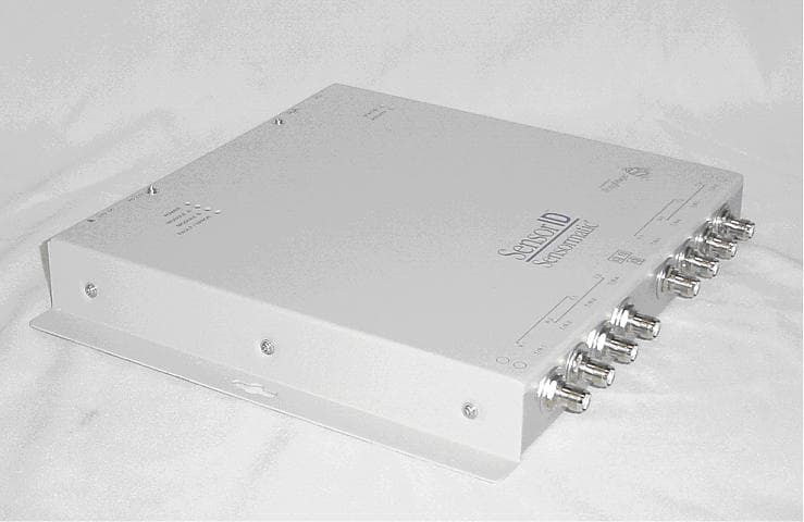
Click to zoom
Application Details
- Equipment Class
- DSS - Part 15 Spread Spectrum Transmitter
- Date of Grant
- Sep 26, 2004
- Application Purpose
- Original Equipment
- Date of Application
- Sep 26, 2004
- Equipment Note
- RFID READER
- Frequency Range
- 902.00000000 - 928.00000000
- Country
- United States
Documents & Files
Document Text
Text extracted from the exhibit documents filed with the FCC. Open a document above to read the original.
Users Manual
AGILE2 READER 8200-0222-08, REV. A INSTALLATION AND SERVICE GUIDE 1 of 13 Agile2 Reader Installation and Service Guide IDRDR2A4UNA 4 Port UHF NA IDRDR2A8UNA 8 Port UHF NA IDRDR2B2UNA 2 Port UHF - NA 1/0 IDRDR2B4UNA 4 Port UHF - NA 1/0 The Agile2 Reader uses RFID (radio frequency identification) technology to read data stored on RFID tags and labels. The reader operates as an SQL (structured query language) server, providing tag data in response to requests from another application. A separate software application may be used to direct its operation and provide a user interface. The reader supports UHF (ultra high frequency) antennas, which are available separately. The reader supports multiple configurations of UHF antenna ports and transfers data to a remote computer either through a wired 10/100 Ethernet connection. The content of this document was developed by ThingMagic LLC. If you need assistance... Call the RFID support line at 800-543-9740. © Sensormatic 2004 Contents About this Guide............................................................. 1 Before You Begin ........................................................... 2 Installation Requirements........................................ 2 Performance Considerations................................... 2 Product Configurations and Part Numbers..................... 3 Authorized Antennas...................................................... 3 Reader Installation ......................................................... 4 Install the Reader .................................................... 4 Install the Antennas................................................ 4 Connect the Reader ................................................ 4 Antenna Connection Options .................................. 5 Configure the Reader.............................................. 6 Service ........................................................................... 7 Using the Browser-Based Interface ........................ 7 Rebooting the Reader ...........................................11 Using Safe Mode .................................................. 11 Specifications............................................................... 12 Declarations ................................................................. 13 About this Guide This installation and service guide explains how to install the Agile2 Reader and use the browser- based interface. Use the instructions provided with the antennas to install and service the antennas. Other related Agile2 Reader documents are: • Regulatory Information for the User, 8200-0222-16 • Query Protocol Reference Guide, 8200-0222-09 • Industrial Enclosure Installation Guide, 8200-0222-11 Antenna Documents: • OmniPoint Antenna Mounting Instructions, 8200-0314-02 • OmniWave Antenna Mounting Instructions, 8200-0314-03 Note: Because customer requirements dictate the placement of reader and antenna components, your Sensormatic representative will supply this information separately. AGILE2 READER 8200-0222-08, REV. A INSTALLATION AND SERVICE GUIDE 2 of 13 Before You Begin Installation Requirements • The reader is shipped with a certified limited power source with a cable length of 1.8m (6ft). • Use only authorized antennas and cables to maintain FCC approval (see Product Configurations and Part Numbers on page 3). • In order to comply with FCC requirements for RF exposure safety, a separation distance of at least 23cm (9in) needs to be maintained between the radiating elements of the antenna and the bodies of nearby persons. • Antennas must be mounted within 7.6m (25ft) cable distance of the reader. • Provide strain relief for all reader connections. • A shielded Ethernet cable must be used to communicate with other devices. • Multiple readers and antennas can be used in combination to enhance detection at specific locations provided the software application is able to synchronize antenna operation. • Recommended minimum configuration for a computer running an application that interfaces with the Agile2 Reader: – Pentium® M 1.40GHz processor – 512MB memory – 20MB hard drive – Microsoft® Windows® 2000 or Windows XP operating system – 10/100 Ethernet® port – CD-ROM drive – Internal 56K modem Performance Considerations Reader performance may be affected by external factors including tag variables and environment. Performance tests conducted under typical operating conditions at your site are recommended to help you optimize system performance. Tag Variables There are several variables associated with tags that can affect reader performance: • Application surface — Some materials interfere with tag performance including metal and moisture. Tags applied to items made from or containing these materials may not perform as expected. • Tag orientation — Reader performance is affected by the orientation of the tag in the antenna field. • Tag model — many tag models are available. Each model has its own performance characteristics. Environment Reader performance may be affected by the following: • Metal surfaces such as desks, filing cabinets, bookshelves, and wastebaskets may enhance or degrade reader performance. Mount antennas as far as possible from metal surfaces that are adversely affecting system performance. • Devices that operate at 900MHz, such as cordless phones and wireless LANs, can interfere with reader performance. These devices may degrade performance of the reader. The reader may also adversely affect performance of 900MHz devices. • Antennas operating in close proximity may interfere with each other, thus degrading reader performance. Interference from other antennas may be eliminated or reduced by using either one or both of the following strategies: – Affected antennas may be coordinated by a separate user application using a time- multiplexing strategy. – Antenna power can be reduced by reconfiguring the RF Transmit Power setting for the reader. AGILE2 READER 8200-0222-08, REV. A INSTALLATION AND SERVICE GUID…
Text truncated - open the document above for the full version.
Cover Letter(s)
September 10th, 2004 Timco Engineering, Inc. 849 N.W. State Road 45 P.O. Box 370 Newberry, Florida 32669 USA Re: Request for withholding from public disclosure proprietary information submitted pursuant to an application for certification of transmitter. FCC ID: BVCIDRDR2 Dear Sir or Madam: Sensormatic Electronics Corporation requests certain materials submitted with this application for certification be withheld from public disclosure. This request is made under the provision of 47 CFR 0.457 (d) and 5 USC 552(b)(4) Freedom of Information Act, Trade Secrets. The items for which confidentiality is requested include the Operational Description, Block Diagram and Schematic Diagrams. This information contains proprietary information (trade secrets) regarding the circuit operation and capabilities (specific values of components, circuit design details and system architecture) that are the result of our extensive investment in research and development. Without the disclosed information, competitive organizations would take considerable more time to assess and develop a workable competitive product. As a result, we believe that disclosure of these company-guarded materials would compromise our leading position in this market. We therefore formally request that the materials identified “Confidential” be kept strictly confidential and not made available for inspections by any other party, except on a need to know basis for the sole purpose of the certification process. Sincerely, William M. Elliott Sr. EMC Engineer, Compliance Engineering Sensormatic Electronics Corporation 6600 Congress Avenue, Boca Raton, FL 33487 Telephone (561) 912-6000 FAX (561) 912-6787
Cover Letter(s)
September 10th, 2004 Timco Engineering, Inc. 849 N.W. State Road 45 P.O. Box 370 Newberry, Florida 32669 USA Re: Request for withholding from public disclosure proprietary information submitted pursuant to an application for certification of transmitter. FCC ID: BVCIDRDR2 Dear Sir or Madam: Sensormatic Electronics Corporation requests certain materials submitted with this application for certification be withheld from public disclosure. This request is made under the provision of 47 CFR 0.457 (d) and 5 USC 552(b)(4) Freedom of Information Act, Trade Secrets. The items for which confidentiality is requested include the Operational Description, Block Diagram and Schematic Diagrams. This information contains proprietary information (trade secrets) regarding the circuit operation and capabilities (specific values of components, circuit design details and system architecture) that are the result of our extensive investment in research and development. Without the disclosed information, competitive organizations would take considerable more time to assess and develop a workable competitive product. As a result, we believe that disclosure of these company-guarded materials would compromise our leading position in this market. We therefore formally request that the materials identified “Confidential” be kept strictly confidential and not made available for inspections by any other party, except on a need to know basis for the sole purpose of the certification process. Sincerely, William M. Elliott Sr. EMC Engineer, Compliance Engineering Sensormatic Electronics Corporation 6600 Congress Avenue, Boca Raton, FL 33487 Telephone (561) 912-6000 FAX (561) 912-6787
Cover Letter(s)
Applicant: Tyco Safety Products/Sensormatic Correspondence Reference Number: 14787 731 Confirmation Number: TC409250 Subject: RE: Request for additional information - FCC ID:BVCIDRDR2 Date of Original FCC Email: 11/02/2004 Dear Mr. Perrine, Please find below the responses to the OET request for additional information regarding FCC ID: BVCIDRDR2: 1) Please provide the scenarios where this device will be installed e.g. store entry, ware house exit. What means will be used to maintain the required 23 cm spacing. Response: 1. Dock doors - where transient activity occurs. 2. Conveyor belt systems - These antennas are patch antennas with a ground plane that minimizes rear/back emissions and provides a forward directional field. The antennas are arranged pointing towards the inside of the conveyor. 3. Shelves - the antenna is recessed inside the shelf where the distance form the radiator would be a minimum of 23 cm when installed according to the manual. These are typical applications but not the only applications. Other applications, not yet defined would also be either transitory, no backfield, or include adequate setback as described above. A statement regarding exposure was crafted with the assistance of the FCC for FCC ID: BVCDMS915. As the Agile 2 reader will be installed and used in similar environments we submit that the same statement is applicable. This statement [copied below for your convenience] appears on the front page of the setup / install manuals as a regulatory requirement for installers. A copy of the applicable page of the setup / installation guide is Appendid as Appendix 1. 2) Please provide photos of the authorized antennas and cables for this device. OmniWave Antenna with supplied 25’ coaxial cable OmniPoint UHF Long and OmniPoint UHF Short Antenna [Supplied with same 25’ cable as pictured above] Matrics Series 1 Antenna with supplied 25’ coaxial cable Please feel free to contact me with any further questions. Sr. EMC Engineer – Compliance Engineering Sensormatic 6600 Congress Avenue Boca Raton, FL 33487 561-912-6462 email: [email protected]
External Photos
Exhibit 6 FCC ID: BVCIDRDR2 IC: 3506A-IDRDR2 Sensormatic® Agile 2 Reader External Photos External Photo 1 – Sensormatic® Agile 2 Reader Front View Exhibit 6 FCC ID: BVCIDRDR2 IC: 3506A-IDRDR2 External Photo 2 – Sensormatic® Agile 2 Reader Side View#1 Exhibit 6 FCC ID: BVCIDRDR2 IC: 3506A-IDRDR2 External Photo 2 – Sensormatic® Agile 2 Reader Side View#2
External Photos
Exhibit 6 FCC ID: BVCIDRDR2 IC: 3506A-IDRDR2 Sensormatic® Agile 2 Reader External Photos External Photo 1 – Sensormatic® Agile 2 Reader Front View Exhibit 6 FCC ID: BVCIDRDR2 IC: 3506A-IDRDR2 External Photo 2 – Sensormatic® Agile 2 Reader Side View#1 Exhibit 6 FCC ID: BVCIDRDR2 IC: 3506A-IDRDR2 External Photo 2 – Sensormatic® Agile 2 Reader Side View#2
ID Label/Location Info
Exhibit 3 FCC ID: BVCIDRDR2 IC: 3506A-IDRDR2 Sensormatic® Agile 2 Reader Label Position Label Position
ID Label/Location Info
Exhibit 2 FCC ID: BVCIDRDR2 IC: 3506A-IDRDR2 Sensormatic® Agile 2 Reader Label Artwork FCC ID: BVCIDRDR2 THIS DEVICE COMPLIES WITH PART 15 OF THE FCC RULES. OPERATION IS SUBJECT TO THE FOLLOWING TWO CONDITIONS: (1) THIS DEVICE MAY NOT CAUSE HARMFUL INTERFERENCE, AND (2) THIS DEVICE MUST ACCEPT ANY INTERFERENCE RECEIVED, INCLUDING INTERFERENCE THAT MAY CAUSE UNDESIRED OPERATION. IC: 3506A-IDRDR2 ALL OUTPUTS ARE CLASS 2, LPS (LIMITED POWER SOURCE) BARCODE MADE IN PUERTO RICO Model: IDRDR2XXXXXX REG ID: IDRDR2 P/N:0101-0092-XX REV : A SERIAL NO: SECA0117012345 MFD:11-04 RATING: 24V 3A ®
Internal Photos
Exhibit 7 FCC ID: BVCIDRDR2 IC: 3506A-IDRDR2 Sensormatic® Agile 2 Reader Internal Photos Internal Photo 1 – Sensormatic® Agile 2 Internal View#1 Exhibit 7 FCC ID: BVCIDRDR2 IC: 3506A-IDRDR2 Internal Photo 2 – Box Top with Absorbing Foam Exhibit 7 FCC ID: BVCIDRDR2 IC: 3506A-IDRDR2 Internal Photo 3 – Digital Board Top View Internal Photo 3 – Digital Board Bottom View Exhibit 7 FCC ID: BVCIDRDR2 IC: 3506A-IDRDR2 4 Port UHF Board Top View 4 Port UHF Board Bottom View Exhibit 7 FCC ID: BVCIDRDR2 IC: 3506A-IDRDR2 2 Port UHF Board Top View 2 Port UHF Board Bottom View
Test Report
FCC ID: BVCIDRDR2 IC: 3506A-IDRDR2 1 COMPANY Sensormatic Electronics Corp. 6600 Congress Ave Boca Raton, Florida 33487 PRODUCT TESTED Sensormatic® Agile 2 Reader FCC ID: BVCIDRDR2 IC: 3506A-IDRDR2 FCC RULES 15.207, 15.209, 15.247 TEST DATE May 6th-August 27th, 2004 SUBMITTED BY William M. Elliott FCC ID: BVCIDRDR2 IC: 3506A-IDRDR2 2 INDEX I. SUMMARY OF RESULTS 3 2. GENERAL INFORMATION 4 Test Methodology / System Description 4 Test Facility 6 EUT Description 7 2I. FREQUENCY HOPPING REQUIREMENTS, 15.247 9 Pseudorandom Frequency Hopping Sequence 9 Equal Hopping Frequency Use 9 DeFacto EIRP Limit 10 System Receiver Hopping Capability 10 System Receiver Input Bandwidth 10 RF Exposure Compliance Information 11 IV. LIST OF MEASUREMENT EQUIPMENT 13 V. DATA 14 Input Voltage Variation 14 AC Conducted Emissions 15 Carrier Frequency Separation 16 Number of Hopping Channels 17 Dwell Time 18 20 dB Bandwidth 19 Peak Power 21 Band Edge Compliance of RF Conducted Emissions 22 Spurious RF Conducted Emissions 24 Spurious Radiated Emissions 26 Fundamental Measurement 26 Spurious Emissions Above 1 GHz 27 Spurious Emissions Below 1 GHz 29 Digital Emissions 32 FCC ID: BVCIDRDR2 IC: 3506A-IDRDR2 3 I. Summary of Results FCC 47 CFR Part [RSS 210 Section] Testing Requirement Test Limits Issues /Comments 15,15 (b)User Accessible Controls N/A The product contains no user accessible controls that increase transmission power above permitted levels. 15.31(e) Vary Input Power N/A Input was varied from 102 to 138 V AC. Input power to antenna was measured. 15.109 [IC 7.3] Radiated Emissions Requirements [Digital Device] See Table 15.109. Unintentional digital emissions subject to Class A limits. Digital emissions determined by turning transmitter off. Complies [Verification]. 15.203 Antenna Requirements Permantantly attached or unique coupling. The antenna connectors are reverse sex TNC connectors, fulfilling the unique connector requirement. Complies. 15.207 (a) (b) [IC 6.6] AC Power Line Conducted Measurements CISPR Class B Limits Conducted emissions on AC side of DC supply is provided in this report. Complies. 15.205 (a) (b) [IC 6.3] 15.209 [IC 6.2.2(o)(e1)] Restricted Band Compliance Must comply with limits Specified in 15.209 (a) The fundamental is not in a restricted band and the spurious emissions in the restricted bands comply with the general emission limits found in 15.209. 15.247 (a) (1) [IC 6.2.2(o)(a1)] Carrier Frequency Separation Separated by minimum of 25 kHz or 20 dB BW of the hopping channel, whichever is greater. The carrier frequencies are separated by at least the 20 dB BW of the hopping channel. Complies. 15.247 (a) (1) (i) [IC 6.2.2(o)(a2)] Number of Hopping Frequencies – 900 MHz TX If 20 dB BW is 250 kHz or greater, then shall use at least 25 hopping channels. The EUT has 50 hopping channels and complies with the requirement. 15.247 (a) (1) (i) [IC 6.2.2(o)(a2)] Dwell Time – Number of Hopping Frequencies > 25 < 0.4 sec within a 10 second period The EUT complies with the requirement. See attached data. 15.247 (a) (1) (i) [IC 6.2.2(o)(a2)] Maximum 20dB Bandwidth Maximum 20 dB BW of the hopping channel cannot exceed 500 kHz. The EUT complies with the requirement. 15.247 (b) (2) (3) [IC 6.2.2(o)(a2)] Output Power 902-928 MHz Tx < 1 W – freq. hopping with 50 channels The EUT complies with the requirement. 15.247 (b) (4) Maximum Antenna Gain If directional gain of transmitting antenna greater than 6 dBi, the peak output power of the device shall be reduced below the stated values in 15.247 (b) (2) and b (3) The antennas used with the device all have gains < 6 dBi. 15.247 (b) (5) [IC Section 14] RF Exposure Must ensure that RF MPE to the public falls within Commission Guidelines See RF Exposure Exhibit. 15.247 c [IC 6.2.2(o)(e1)] Band-edge Compliance of RF Emissions In any 100 kHz bandwidth outside the frequency band in which the spread spectrum intentional radiator is operating, the radio frequency power that is produced by the intentional radiator shall be at least 20 dB below that in the 100 kHz bandwidth within the band that contains the highest level of the desired power The EUT complies with the band-edge requirements. No band-edge emissions fall within restricted bands. See submitted data. 15.247 c [IC 6.2.2(o)(e1)] Radiated Restricted Band Emissions Requirements Must comply with limits Specified in 15.209 (a) The spurious emissions in the restricted bands from this device comply with the emission limits found in 15.209. 15.247 (g) (h) See appropriate sections of report. FCC ID: BVCIDRDR2 IC: 3506A-IDRDR2 4 II. General Information This report is part of the application for Certification of a RFID reader operating in the 902-928 MHz bands under the rules provided for frequency-hopping spread spectrum transmitters found in 47 CFR 15.247. The product covered by this report is the Sensormatic Agile 2 Reader. Test Methodology The Agile 2 is a RFID reader designed to operate in the UHF band 902 MHz to 928 MHz. The reader is divided into three sub-modules (1) Digital board and (2) two UHF radio modules connected to the digital board through a 60 pin bus (figure1). The digital board contains all remote interface, data acquisition, processor/DSP, voltage distribution, and two RF slots. Each UHF module is a full CW radio transceiver with 30 dBm maximum output power . There are currently two versions of the UHF radio module distinguished as a 4-port or a 2-port. The 4-port UHF module combines the receive path and the transmit path onto a single path through the use of a ferrite circulator. This path is then switched to one of four antennas. The 2-port UHF module has separate isolated receive and transmit antenna connections. The receive path may be switched to one of two antennas. The transmit path may be also switched to one of two antennas. The receive and transmit antennas are in a single housing, and are isolated from one another. Other than that, the circuitry is identical for both boards. Each port is f…
Text truncated - open the document above for the full version.
Test Setup Photos
Exhibit 10 FCC ID: BVCIDRDR2 IC: 3506A-IDRDR2 Test Setup Photos Conducted Emissions Exhibit 10 FCC ID: BVCIDRDR2 IC: 3506A-IDRDR2 Radiated Emissions Exhibit 10 FCC ID: BVCIDRDR2 IC: 3506A-IDRDR2 Radiated Emissions
Contact Information
Applicant
Mark D. Alexis(Manager Regulatory Compliance)
Test Firm
Sensormatic Electronics CorporationWilliam Elliott
Technical Specifications
| # | Rule Parts | Frequency Range | Power Output |
|---|---|---|---|
| 1 | 15C | 902 MHz - 928 MHz | 1 W |
Other Applications from Tyco Safety Products/Sensormatic

BVCIDX5000
Jun 23, 2026UHF RFID Reader
Equipment Class
DSS - Part 15 Spread Spectrum TransmitterBVCAMS1137H
Dec 22, 2025Anti Theft System - Electronic Asset Security
Equipment Class
FAP - Part 15 Anti-Pilferage DeviceBVCAMB9012
Sep 10, 2024Label Deactivator Controller
Equipment Class
DCD - Part 15 Low Power Transmitter Below 1705 kHz
BVC-4000-PI26
Sep 24, 2015RM2L-4000-P126, RM2-4000-P126
Equipment Class
DXX - Part 15 Low Power Communication Device Transmitter
BVCAMS90604
May 20, 2014Anti-pilferage Device
Equipment Class
FAP - Part 15 Anti-Pilferage Device