BVCIDX9000PART 15.247 SPREAD SPECTRUM TRANSMITTER, RFID READER
Tyco Safety Products/Sensormatic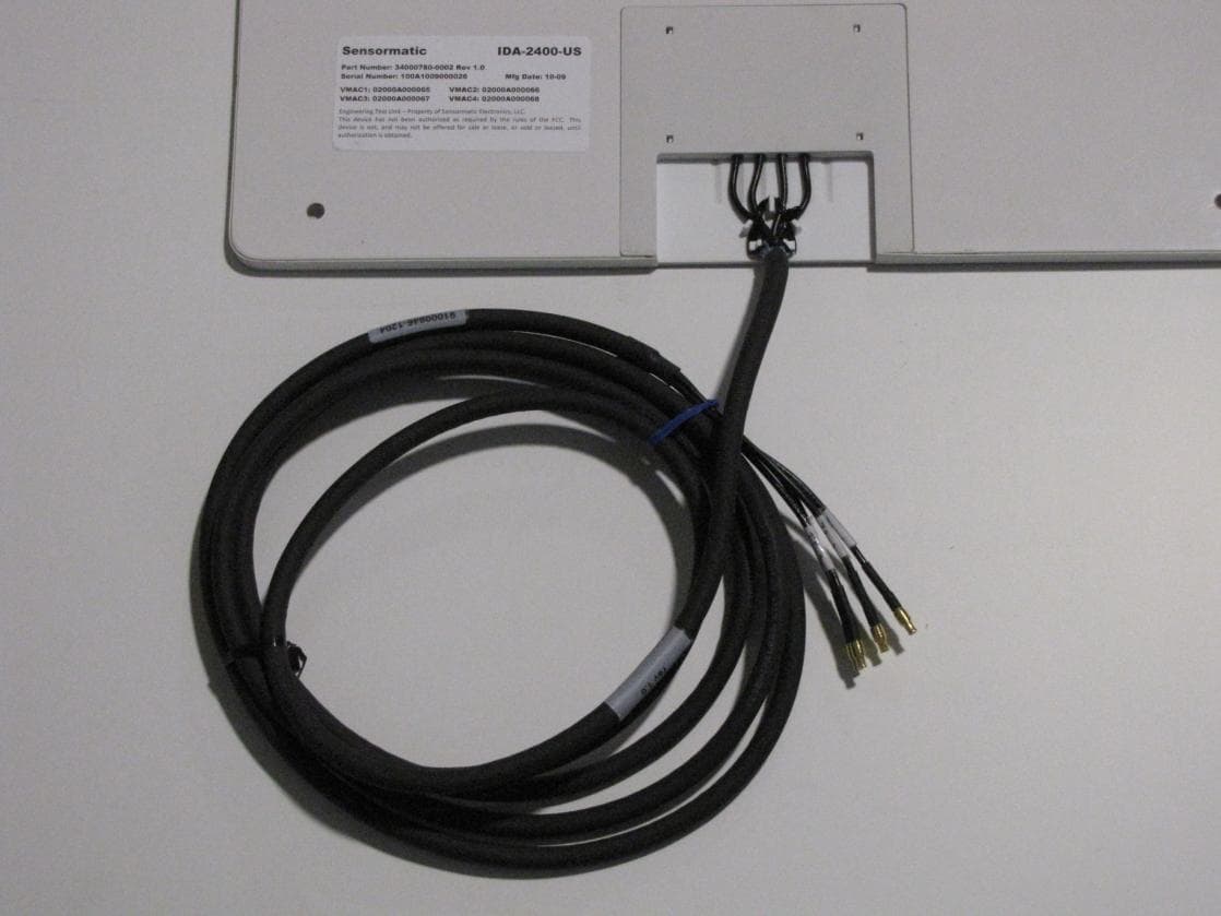
Click to zoom
Application Details
- Equipment Class
- DSS - Part 15 Spread Spectrum Transmitter
- Date of Grant
- Apr 25, 2010
- Application Purpose
- Original Equipment
- Date of Application
- Apr 25, 2010
- Equipment Note
- PART 15.247 SPREAD SPECTRUM TRANSMITTER, RFID READER
- Frequency Range
- 902.74000000 - 927.25000000
- Country
- United States
Documents & Files
Document Text
Text extracted from the exhibit documents filed with the FCC. Open a document above to read the original.
Users Manual
IDX-9000 User Guide Introduction This users guide provides overview information for the IDX-9000; which includes models IDX-9000-US, IDX-9000-EU, IDX-9000-JP, with corresponding part numbers 34000774- 0005, 34000774-1005, 34000774-2005, respectively for the US, EU, and Japan. The IDX-9000 Users Guide includes LED definitions, port descriptions, connection and mounting information, as well as regulatory and compliance information. References to IDX-9000 apply to all versions, except where the version is explicitly identified. This device received all regulatory approvals under the name Sensormatic Electronics. Vue Technology is the RFID business unit of Sensormatic Electronics. LED Definitions See the top view illustration below for the LED positions on the IDX-9000. LED State Description Error Off Flashing No known error conditions. Flashes when the power on cycle is initiated. If flashing after initial power on cycle, the unit has detected errors during self- test. If errors are detected, contact Technical Support. RF On Off RF transmitter is turned on and transmitting. No RF output. Tag On Off Valid tag(s) are found and being read. Tags are not currently being read. Power On Off Flashing Power is on and unit is ready. No power to the unit. Unit is powering on. All LEDs are off when the power is not connected. All LEDs will be on briefly and cycle their display when the power is reset. The Green, Yellow1, and Yellow2 LEDs will cycle when in a downloading state. Mounting Position the IDX-9000 on the wall or shelf, ensuring a minimum clearance of five inches on all sides. Mark the hole locations using the mounting tabs as a guide. The distance between mounting holes across the width of the connector panels is 200 mm. The distance between mounting holes across the length of the unit is 226 mm. Remove the IDX-9000 and drill four mounting holes at the marked locations. Reposition the IDX-9000 over the mounting holes and secure using fasteners appropriate for its 3.5- pound weight, the mounting surface, and any other conditions present, such as vibration. 226 mm 200 mm Power Tag RF Error Physical Connections The physical connections to the IDX-9000 device are shown in the graphics below RF Side Ports Digital Side Ports RF Side Port Description EXT RF A External RF Port A (Reverse SMA) EXT RF B External RF Port B (Reverse SMA) RF Outputs 1-16 Monostatic RF Output Ports (MCX) Digital Side Port Description Power BUS 1-3 Power supply port. Connect the Sensormatic approved power supply to any of the three ports. The power supply uses an AC adapter that varies, depending on the country. Maximum power consumption: 24 VDC, 1.33A. LAN1 LAN2 LAN3 10/100 Base-T Ethernet Port. Insert a standard RJ45 Ethernet cable for connection to an Ethernet network. Insert a cross-connect Ethernet cable for connection to a local PC. The left LED indicates link/activities. The LED turns on when the link is established and flashes when data packets are sent or received. The right LED indicates speed. When the left LED is on, the right LED turns on when the port is linked at 100 Mbps and turns off when the port is linked at 10 Mbps. GPIO General Purpose Input/Output (15 pin) Port. Insert a DE15 cable assembly for connection to an external device. RS-232 Serial Port For serial device connection. Regulatory Information All Sensormatic devices are designed to be compliant with rules and regulations in locations in which they are sold and are labeled, as required. Any changes or modifications to Sensormatic equipment, not expressly approved, in writing, by Sensormatic could void the authority to operate the equipment. Country Approvals Regulatory markings are applied to the device signifying the radio(s) are approved for use in the following countries: United States, and Canada,. Health and Safety Recommendations Operation of the device without regulatory approval is illegal. Warning for Use of Wireless Devices Please observe all warning notices with regard to usage of wireless devices. Potentially Hazardous Atmospheres You are reminded of the need to observe restrictions on the use of radio devices in fuel depots., chemical plants, etc., and areas where the air contains chemicals or particles (such as grain, dust, or metal powders) and any other area where you would normally be advised to turn off your vehicle engine. Safety in Hospitals Wireless devices transmit radio frequency energy and may affect medical electrical equipment. When installed adjacent to other equipment, it is advised to verify that the adjacent equipment is not adversely effected. Hearing Aids The wireless device may interfere with some hearing aids. In the event of interference, you may want to consult your hearing aid supplier to discuss solutions. Other Medical Devices Please consult your physician or the manufacturer of the medical device to determine if the operation of your wireless product may interfere with medical devices. Remote and Standalone Antenna Configurations The antennas used with this transmitter must be installed to provide a minimum separation distance of 25 cm from all persons and must not be co-located or operated in conjunction with any other antenna or transmitter. End users and installers must be provided with antenna installation instructions and transmitter operating conditions for satisfying RF exposure compliance. Power Supply Use only the Sensormatic Electronics power supply provided with this unit or other power supply approved by and obtained from Sensormatic for use with this product. Wireless Devices - Countries If frequency is selectable for your model, select only the country in which you are using the device. Any other selection will make the operation of this device illegal. Frequency of Operation - FCC and IC (US/Canada Versions) The unit operates from 902-928 Mhz at a maximum power level of 1W. Federal Communications Commission (FCC) This equipment has been tested and found to comply with the limits for a Class B …
Text truncated - open the document above for the full version.
Cover Letter(s)
March 18, 2010 Timco Engineering, Inc. 849 N.W. State Road 45 P.O. Box 370 Newberry, Florida 32669 USA Re: Application for a Confidential Request for Anti-Pilferage Device, FCC ID: BVCIDX9000 Dear Sir or Madam: Federal Communications Commission Authorization and Evaluation Division Confidentiality Request regarding application for certification. Pursuant to Sections 0.457 and 0.459 of the Commission’s Rules, we hereby request confidential treatment of information accompanying this application as outlined below: IDX9000 Conf OpDes.pdf IDX9000 Conf Schem.pdf IDX9000 Conf BlkDia.pdf The above materials contain trade secrets and proprietary information not customarily released to the public. The public disclosure of these materials may be harmful to the applicant and provide unjustified benefits to its competitors. The applicant understands that pursuant to Section 0.457 of the Rules, disclosure of this application and all accompanying documentation will not be made before the date of the Grant for this application. Sincerely, William D. Owsley Principal EMC Engineer Compliance Engineering Tyco Retail Solutions Sensormatic Electronics, LLC. 6600 Congress Ave. Boca Raton, FL. 33487
External Photos
Antenna Photos – 4 Patches in protective cover MCX connectors to radio Single Patch in Decorative cover Single Patch in protective cover
External Photos
IDX9000 External Photos
ID Label/Location Info
IDX9000 Label Location – bottom of unit. No label available at time of photo.
ID Label/Location Info
Label Sample
Internal Photos
IDX9000 Internal Photos
RF Exposure Info
IDX9000 RF Exposure Analysis RF Exposure Compliance Requirements Operating Band Center Frequency = 915 MHz EUT Output Power = +30 dBm Antenna Gain = 6 dBi => Numeric Gain = 4 Power Density Limit for General Population is S = F(MHz) / 1500 = 0.61 mW / cm^2 or 6100 W/m^2 (CFR 47 Part 1.1310, Table 1) Minimum MPE safe distance (using equation below) = 10.2mm Calculations: Assuming 1 watt output power into a maximum 6 dBi gain antenna, neglecting for cable losses to the antenna gives a 2 watt total output. Power Density Pd = (Pt*G)/(4*pi*d^2) Pd = (2watt*4gain)/(4*pi*0.25^2) at 25 cm distance Pd = (8)/(0.785) = 10.2 W/m^2 where limit is 6100 W/m^2 Or to find the safe distance that meets the MPE limit; Power Density Pd = (Pt*G)/(4*pi*d^2) Solve for d, the minimum safe distance to meet the MPE limit. d^2 = (Pt*G)/(4*pi*Pd) d = SqrRoot((Pt*G)/(4*pi*Pd)) d = SqrRoot((2watt*4gain)/(4*pi*6100watt/m^2) d = SqrRoot((2/pi*6100)m^2) d = SqrRoot(2/pi*6100)m d = 0.0102meters = 10.2 mm Where E = Field Strength in Volts/meter Pt= Transmit Power In Watts G = Numeric Antenna Gain d = Distance in Meters Pd = Power Density in W / square m
Test Report
Page 1 of 30 TYCO SAFETY PRODUCTS SENSORMATIC EMC TEST REPORT Model: IDX-9000-US FCC ID: BVCIDX9000 IC: 3506A-IDX9000 Intentional Radiator FCC 47 CFR, Part 15, Subpart C Industry Canada RSS-210 Date: Jan. 4, 2010 EMC Engineer Page 2 of 30 Table of contents Summary of Results ............................................................................................................................................................................... 3 General Information ............................................................................................................................................................................... 4 EUT Description .................................................................................................................................................................................... 5 INPUT VOLTAGE VARIETION, 15.31(e) .......................................................................................................................................... 8 AC CONDUCTED EMISSIONS, 15.207 and 15.107 ........................................................................................................................... 9 FREQUENCY HOPPING REQUIREMENT, 15.247 ......................................................................................................................... 12 CARRIER FREQUENCY SEPARATION, 15.247 (a)(1) ................................................................................................................... 13 NUMBER OF HOPPING CHANNELS, 15.247 (a)(1)(i) ................................................................................................................... 14 TIME OF OCCUPANCY (DWELL TIME), 15.247 (a)(1)(i) ............................................................................................................. 15 20 DB BANDWIDTH, 15.247 (a)(1) .................................................................................................................................................. 16 PEAK POWER OUTPUT, 15.247 (b) ................................................................................................................................................. 17 BAND-EDGE COMPLIANCE OF RF CONDUCTED EMISSIONS, 15.247 (c) .............................................................................. 20 SPURIOUS RF CONDUCTED EMISSIONS, 15.247 (c) ................................................................................................................... 21 SPURIOUS RADIATED EMISSIONS, 15.247 (c), 15.205, 15.209 ................................................................................................... 23 Test Equipment List ............................................................................................................................................................................. 30 Page 3 of 30 Summary of Results FCC 47 CFR Part 15. Subpart C. Test Requirement Test Limit Comments 15,15 (b) User Accessible Controls Cannot change output power above limit. The product contains no user accessible controls that increase transmission power above permitted levels. 15.31 (e) Vary Input Power Does not increase the output power above the limit. Input was varied from 102 to 138 VAC. Input power to antenna was measured. Complies. 15.107 AC Mains Conducted Emissions Requirements [Digital Device] See Table 15.107. Unintentional digital emissions subject to Class A limits. Digital emissions determined by turning transmitter off. Complies [Verification]. 15.109 Radiated Emissions Requirements [Digital Device] See Table 15.109. Unintentional digital emissions subject to Class A limits. Digital emissions determined by turning transmitter off. Complies [Verification]. 15.203 Antenna Connector Requirements Permanently attached or unique coupling. The radio to antenna connectors are MCX to RP TNC connectors. Complies. 15.207 (a) (b) AC Mains Conducted Emissions Requirements. General Limits. Equivalent to15.109 Class B. Conducted emissions on AC side of DC supply. . Complies. 15.205 (a) (b) 15.209 Restricted Band Compliance Must comply with limits specified in 15.209 (a). Equivalent to15.109 Class B. The spurious emissions in the restricted bands comply with the general emission limits. 15.247 (a) (1) Carrier Frequency Separation Separated by minimum of 25 kHz or 20 dB BW of the hopping channel, whichever is greater. The carrier frequencies are separated by at least the 20 dB BW of the hopping channel. Complies. 15.247 (a) (1) (i) Number of Hopping Frequencies . If 20 dB BW is less than 250 kHz, then shall use at least 50 hopping channels, using frequencies in a pseudo random list. The EUT has 50 hopping channels and complies with the requirement. 15.247 (a) (1) (i) Dwell Time – Number of Hopping Frequencies > 25 < 0.4 sec within a 20 second period The EUT complies with the requirement. 15.247 (b) (2) (3) Output Power 902- 928 MHz Tx Maximum 1 W – frequency hopping with 50+ channels The EUT complies with the requirement. 15.247 (b) (4) Maximum Antenna Gain If directional gain of transmitting antenna greater than 6 dBi, the peak output power of the device shall be reduced below the stated values by the amount in dB exceeding 6 dBi. Permanently attached attenuators on each antenna ensure compliance. 15.247 (b) (5) RF Exposure Must ensure that RF MPE to the public falls within Commission Guidelines See RF Exposure Section. These results are deemed satisfactory evidence of compliance with Industry Canada Interference-Causing Equipment Standard ICES-003 and Radio Standard RSS-210. Page 4 of 30 General Information The product covered by this report is the Sensormatic IDX-9000-US Reader. This report is part of the application for Certification of a RFID reader operating in the 902-928 MHz bands under the rules provided for frequency-hopping transmitters found in 47 CFR subpart C, 15.247. The digital portion of the radio was evaluated according to the Verification procedures for a Cla…
Text truncated - open the document above for the full version.
Test Setup Photos
IDX9000 Test Setup Photos IDX9000 Test Setup Photos – Conducted Emissions IDX9000 Test Setup Photos IDX9000 Test Setup Photos – Radiated Emissions. Pre-compliance chamber. IDX9000 Test Setup Photos Multiple patch antennas in one package. IDX9000 Test Setup Photos Shows alternate RFID antenna position. IDX9000 Test Setup Photos Different antenna package. IDX9000 Test Setup Photos Single RFID antenna IDX9000 Test Setup Photos Different Radio orientation – horizontal and vertical.
Contact Information
Applicant
Mark D. Alexis(Manager Regulatory Compliance)
Test Firm
Tyco Safety Products / SensormaticWilliam Owsley
[email protected]561-912-6462
Technical Specifications
| # | Rule Parts | Frequency Range | Power Output |
|---|---|---|---|
| 1 | 15C | 902.74 MHz - 927.25 MHz | 1 W |
Other Applications from Tyco Safety Products/Sensormatic

BVCIDX5000
Jun 23, 2026UHF RFID Reader
Equipment Class
DSS - Part 15 Spread Spectrum TransmitterBVCAMS1137H
Dec 22, 2025Anti Theft System - Electronic Asset Security
Equipment Class
FAP - Part 15 Anti-Pilferage DeviceBVCAMB9012
Sep 10, 2024Label Deactivator Controller
Equipment Class
DCD - Part 15 Low Power Transmitter Below 1705 kHz
BVC-4000-PI26
Sep 24, 2015RM2L-4000-P126, RM2-4000-P126
Equipment Class
DXX - Part 15 Low Power Communication Device Transmitter
BVCAMS90604
May 20, 2014Anti-pilferage Device
Equipment Class
FAP - Part 15 Anti-Pilferage Device